sensor Hyundai Palisade 2020 Repair Manual
[x] Cancel search | Manufacturer: HYUNDAI, Model Year: 2020, Model line: Palisade, Model: Hyundai Palisade 2020Pages: 611, PDF Size: 18.86 MB
Page 451 of 611
5-142
Driving your vehicle
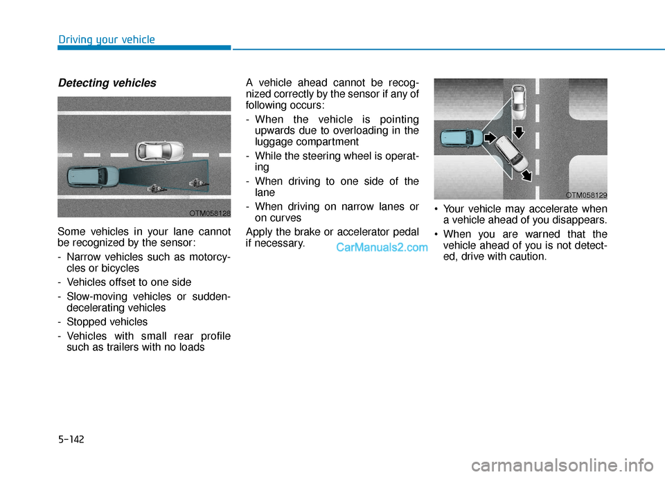
Detecting vehicles
Some vehicles in your lane cannot
be recognized by the sensor:
- Narrow vehicles such as motorcy-cles or bicycles
- Vehicles offset to one side
- Slow-moving vehicles or sudden- decelerating vehicles
- Stopped vehicles
- Vehicles with small rear profile such as trailers with no loads A vehicle ahead cannot be recog-
nized correctly by the sensor if any of
following occurs:
- When the vehicle is pointing
upwards due to overloading in the
luggage compartment
- While the steering wheel is operat- ing
- When driving to one side of the lane
- When driving on narrow lanes or on curves
Apply the brake or accelerator pedal
if necessary. Your vehicle may accelerate when
a vehicle ahead of you disappears.
When you are warned that the vehicle ahead of you is not detect-
ed, drive with caution.
OTM058128
OTM058129
Page 488 of 611
6-10
What to do in an emergency
If any of the below happens, have
the system checked by an author-
ized HYUNDAI dealer.
1.The Low Tire Pressure TPMS Malfunction Indicator does not
illuminate for 3 seconds when
the ignition switch is placed to
the ON position or engine is run-
ning.
2.The TPMS Malfunction Indicator remains illuminated after blink-
ing for approximately 1 minute.
3.The Low Tire Pressure LCD dis- play remains illuminated
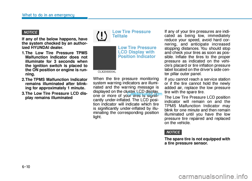
Low Tire Pressure
Telltale
Low Tire Pressure
LCD Display with
Position Indicator
When the tire pressure monitoring
system warning indicators are illumi-
nated and the warning message is
displayed on the cluster LCD display,
one or more of your tires is signifi-
cantly under-inflated. The LCD posi-
tion indicator will indicate which tire
is significantly under-inflated by illu-
minating the corresponding position
light. If any of your tire pressures are indi-
cated as being low, immediately
reduce your speed, avoid hard cor-
nering, and anticipate increased
stopping distances. You should stop
and check your tires as soon as pos-
sible. Inflate the tires to the proper
pressure as indicated on the vehi-
cle’s placard or tire inflation pressure
label located on the driver's side cen-
ter pillar outer panel.
If you cannot reach a service station
or if the tire cannot hold the newly
added air, replace the low pressure
tire with the spare tire.
The Low Tire Pressure LCD position
indicator will remain on and the
TPMS Malfunction Indicator may
blink for one minute and then remain
illuminated until you have the low
pressure tire repaired and replaced
on the vehicle.
The spare tire is not equipped with
a tire pressure sensor.
NOTICE
NOTICE
OLX2068004L
Page 490 of 611
6-12
What to do in an emergency
The TPMS Malfunction Indicator
may illuminate after blinking for
one minute if the vehicle is near
electric power supply cables or
radio transmitters such as police
stations, government and public
offices, broadcasting stations,
military installations, airports,
transmitting towers, etc.
Additionally, the TPMS Malfunction
Indicator may illuminate if snow
chains are used or electronic
devices such as computers, charg-
ers, remote starters, navigation,
etc. This may interfere with normal
operation of the TPMS.
Changing a Tire with TPMS
If you have a flat tire, the Low Tire
Pressure and LCD position indicator
will come on. Have the flat tire
repaired by an authorized HYUNDAI
dealer as soon as possible or
replace the flat tire with the spare
tire.
The spare tire does not come with a
tire pressure monitoring sensor.
When the low pressure tire or the flat
tire is replaced with the spare tire,
the Low Tire Pressure LCD position
indicator will remain on. Also, the
TPMS Malfunction Indicator will illu-
minate after blinking for one minute if
the vehicle is driven at speed above
15.5 mph (25 km/h) for approximate-
ly 20 minutes. Once the original tire equipped with
a tire pressure monitoring sensor is
reinflated to the recommended pres-
sure and reinstalled on the vehicle,
the Low Tire Pressure LCD position
indicator and TPMS Malfunction
Indicator will go off within a few min-
utes of driving.
If the indicators do not disappear
after a few minutes, please visit an
authorized HYUNDAI dealer.
Each wheel is equipped with a tire
pressure sensor mounted inside the
tire behind the valve stem (except for
the spare tire). You must use TPMS
specific wheels. It is recommended
that you always have your tires serv-
iced by an authorized HYUNDAI
dealer.
NOTICE
Never use a puncture-repairing
agent not approved by HYUNDAI
dealer to repair and/or inflate a
low pressure tire. Tire sealant
not approved by HYUNDAI deal-
er may damage the tire pressure
sensor.
CAUTION
Page 501 of 611
6-23
What to do in an emergency
6
When towing your vehicle in an
emergency without wheel dollies:
1. Place the ignition switch in theACC position.
2. Place the shift button in N (Neutral).
3. Release the parking brake.
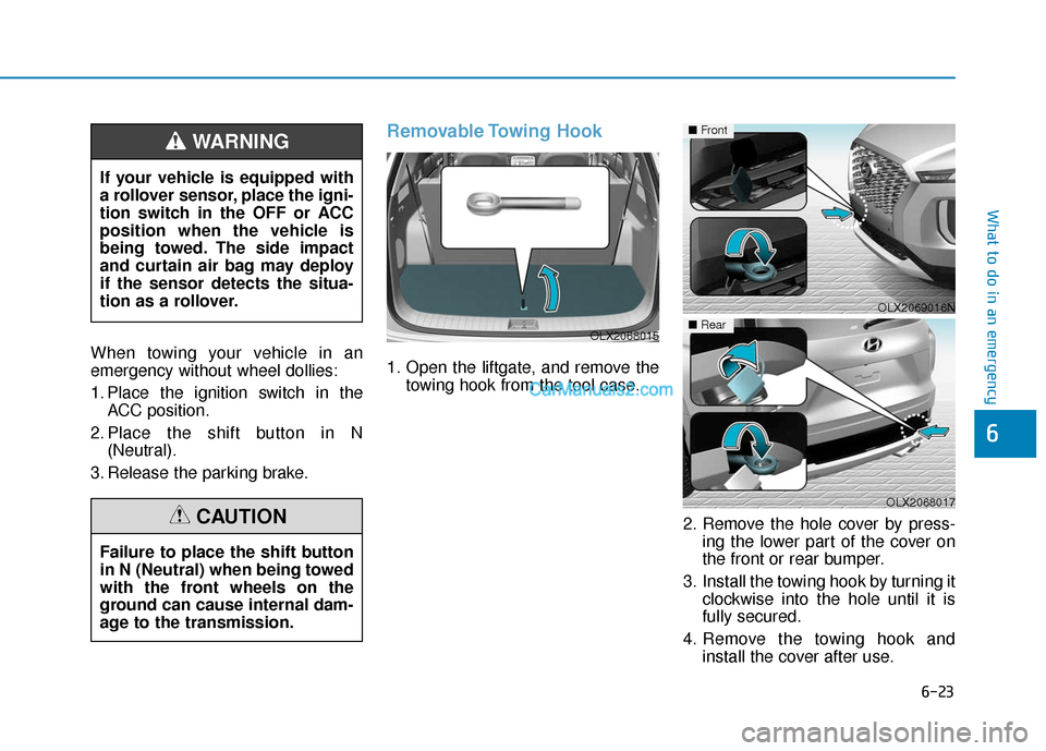
Removable Towing Hook
1. Open the liftgate, and remove the towing hook from the tool case.
2. Remove the hole cover by press-ing the lower part of the cover on
the front or rear bumper.
3. Install the towing hook by turning it clockwise into the hole until it is
fully secured.
4. Remove the towing hook and install the cover after use.
OLX2069016N
■Front
OLX2068017
If your vehicle is equipped with
a rollover sensor, place the igni-
tion switch in the OFF or ACC
position when the vehicle is
being towed. The side impact
and curtain air bag may deploy
if the sensor detects the situa-
tion as a rollover.
WARNING
Failure to place the shift button
in N (Neutral) when being towed
with the front wheels on the
ground can cause internal dam-
age to the transmission.
CAUTION
OLX2068015■Rear
Page 527 of 611
7-24
Maintenance
Information
If the vehicle is operated in extremely
dusty or sandy areas, replace the air
cleaner filter more often than the
usual recommended intervals (refer to
"Maintenance Under Severe Usage
Conditions" in this chapter).
Do not drive with the air cleanerfilter removed. This will result in
excessive engine wear.
When removing the air cleaner filter, be careful that dust or dirt
does not enter the air intake, or
damage may result.
Use HYUNDAI genuine parts. Use of non-genuine parts could
damage the air flow sensor.
Filter Inspection
The climate control air filter should
be replaced according to the
Maintenance Schedule. If the vehicle
is operated in severely air-polluted
cities or on dusty rough roads for a
long period and/or if transporting
pets or occupants smoke inside the
vehicle, then it should be inspected
more frequently and replaced soon-
er. Replace the climate control air fil-
ter by following the procedure below
and be careful to avoid damaging
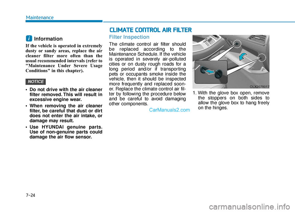
other components. 1. With the glove box open, remove
the stoppers on both sides to
allow the glove box to hang freely
on the hinges.
NOTICE
i
C CL
LI
IM
M A
AT
TE
E
C
C O
O N
NT
TR
R O
O L
L
A
A I
IR
R
F
F I
IL
L T
T E
ER
R
OLX2078017
Page 555 of 611
7-52
Maintenance
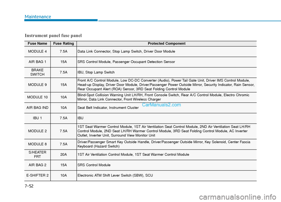
Fuse NameFuse RatingProtected Component
MODULE 47.5AData Link Connector, Stop Lamp Switch, Driver Door Module
AIR BAG 115ASRS Control Module, Passenger Occupant Detection Sensor
BRAKE
SWITCH7.5AIBU, Stop Lamp Switch
MODULE 915AFront A/C Control Module, Low DC-DC Converter (Audio), Power Tail Gate Unit, Driver IMS Control Module,
Head-up Display, Driver Door Module, Driver/Passenger Power Outside Mirror, Security Indicator, Rain Sensor,
Rear Occupant Alert (ROA) Sensor, 3RD Seat Folding Control Module
MODULE 1010ABlind-Spot Collision Warning Unit LH/RH, Front Console Switch, Rear A/C Control Module, Electro Chromic
Mirror, Data Link Connector, Front Wireless Charger
AIR BAG IND10ASeat Belt Indicator, Instrument Cluster
IBU 17.5AIBU
MODULE 27.5A1ST Seat Warmer Control Module, 1ST Air Ventilation Seat Control Module, 2ND Air Ventilation Seat LH/RH
Control Module, 2ND Seat LH/RH Warmer Control Module, 3RD Seat Folding Control Module, AC Inverter
Outlet, Inverter Unit, Surround View Monitor Unit
MODULE 87.5ADriver/Passenger Smart Key Outside Handle, Driver/Passenger Outside Mirror, Key Solenoid, Center Fascia
Keyboard (Hazard Switch)
S/HEATER FRT20A1ST Air Ventilation Control Module, 1ST Seat Warmer Control Module
AIR BAG 215ASRS Control Module
E-SHIFTER 210AElectronic ATM Shift Lever Switch (SBW), SCU
Instrument panel fuse panel
Page 561 of 611
7-58
Maintenance
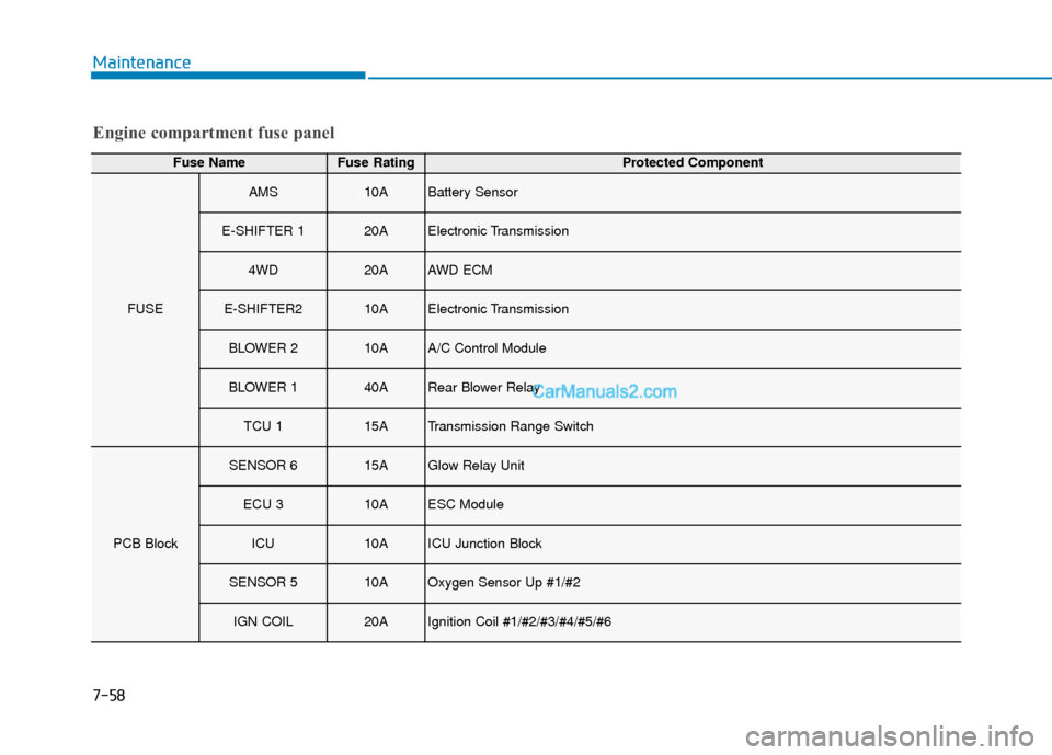
Engine compartment fuse panel
Fuse NameFuse RatingProtected Component
FUSE
AMS10ABattery Sensor
E-SHIFTER 120AElectronic Transmission
4WD20AAWD ECM
E-SHIFTER210AElectronic Transmission
BLOWER 210AA/C Control Module
BLOWER 140ARear Blower Relay
TCU 115ATransmission Range Switch
PCB Block
SENSOR 615AGlow Relay Unit
ECU 310AESC Module
ICU10AICU Junction Block
SENSOR 510AOxygen Sensor Up #1/#2
IGN COIL20AIgnition Coil #1/#2/#3/#4/#5/#6
Page 562 of 611
![Hyundai Palisade 2020 Repair Manual 7-59
7
Maintenance
Engine compartment fuse panel
Fuse NameFuse RatingProtected Component
PCB Block
SENSOR 110AFuel Pump Relay
A/C 110A[2.4 GDI] A/CON Relay
WIPER FRT 130AWiper Main Relay
TCU 210ATCM, Hyundai Palisade 2020 Repair Manual 7-59
7
Maintenance
Engine compartment fuse panel
Fuse NameFuse RatingProtected Component
PCB Block
SENSOR 110AFuel Pump Relay
A/C 110A[2.4 GDI] A/CON Relay
WIPER FRT 130AWiper Main Relay
TCU 210ATCM,](/img/35/16309/w960_16309-561.png)
7-59
7
Maintenance
Engine compartment fuse panel
Fuse NameFuse RatingProtected Component
PCB Block
SENSOR 110AFuel Pump Relay
A/C 110A[2.4 GDI] A/CON Relay
WIPER FRT 130AWiper Main Relay
TCU 210ATCM, SBW Controller
ECU 320APCM
B/ALARM HORN15ABurglar Alarm Horn Relay
HORN15AHorn Relay
FUEL PUMP20AFuel Pump Relay
ECU 120APCM
SENSOR 210AA/C Comp Relay, Variable Intake Solenoid Valve, Oil Pump Solenoid Valve, Oxygen
Sensor Down, Oil Control Valve, Electronic Thermostat Heater, Purge Control Solenoid
Valve
ECU 220APCM
POWER OUTLET 120ARear Power Outlet 1
Maintenance
7
Page 563 of 611
7-60
Maintenance
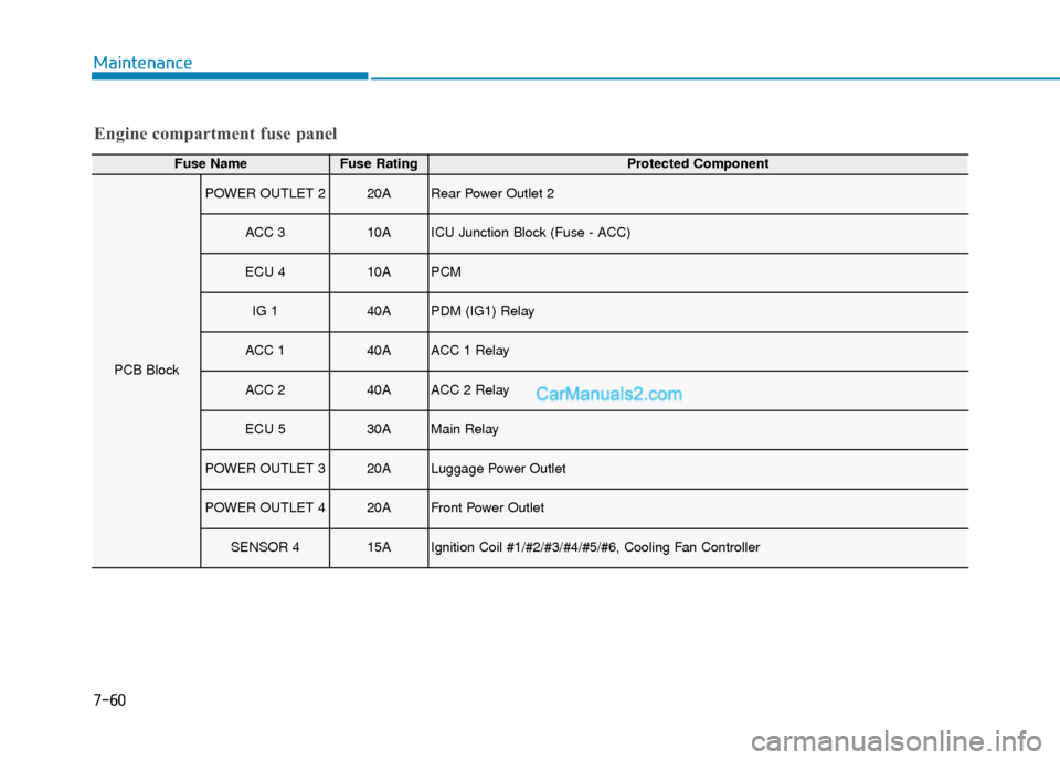
Engine compartment fuse panel
Fuse NameFuse RatingProtected Component
PCB Block
POWER OUTLET 220ARear Power Outlet 2
ACC 310AICU Junction Block (Fuse - ACC)
ECU 410APCM
IG 140APDM (IG1) Relay
ACC 140AACC 1 Relay
ACC 240AACC 2 Relay
ECU 530AMain Relay
POWER OUTLET 320ALuggage Power Outlet
POWER OUTLET 420AFront Power Outlet
SENSOR 415AIgnition Coil #1/#2/#3/#4/#5/#6, Cooling Fan Controller
Page 573 of 611
7-70
Maintenance
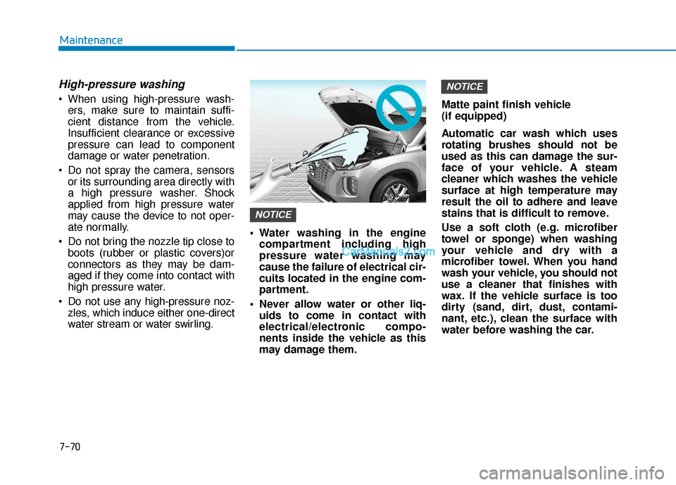
High-pressure washing
When using high-pressure wash-ers, make sure to maintain suffi-
cient distance from the vehicle.
Insufficient clearance or excessive
pressure can lead to component
damage or water penetration.
Do not spray the camera, sensors or its surrounding area directly with
a high pressure washer. Shock
applied from high pressure water
may cause the device to not oper-
ate normally.
Do not bring the nozzle tip close to boots (rubber or plastic covers)or
connectors as they may be dam-
aged if they come into contact with
high pressure water.
Do not use any high-pressure noz- zles, which induce either one-direct
water stream or water swirling. Water washing in the engine
compartment including high
pressure water washing may
cause the failure of electrical cir-
cuits located in the engine com-
partment.
Never allow water or other liq- uids to come in contact with
electrical/electronic compo-
nents inside the vehicle as this
may damage them. Matte paint finish vehicle
(if equipped)
Automatic car wash which uses
rotating brushes should not be
used as this can damage the sur-
face of your vehicle. A steam
cleaner which washes the vehicle
surface at high temperature may
result the oil to adhere and leave
stains that is difficult to remove.
Use a soft cloth (e.g. microfiber
towel or sponge) when washing
your vehicle and dry with a
microfiber towel. When you hand
wash your vehicle, you should not
use a cleaner that finishes with
wax. If the vehicle surface is too
dirty (sand, dirt, dust, contami-
nant, etc.), clean the surface with
water before washing the car.
NOTICE
NOTICE
OLX2078045