bulb Hyundai Santa Fe 2005 Owner's Manual
[x] Cancel search | Manufacturer: HYUNDAI, Model Year: 2005, Model line: Santa Fe, Model: Hyundai Santa Fe 2005Pages: 277, PDF Size: 10.53 MB
Page 68 of 277
1
FEATURES OF YOUR HYUNDAI
57
MULTI-FUNCTION LIGHT SWITCHB340A01A-AATCOMBINATION TURN SIGNAL,
HEADLIGHT AND HIGH-BEAM
SWITCH
Turn Signal OperationPulling down on the lever causes the turn
signals on the left side of the car to blink. Pushing
upwards on the lever causes the turn signals on
the right side of the car to blink. As the turn is
completed, the lever will automatically return to
the center position and turn off the turn signals
at the same time. If either turn signal indicator
light blinks more rapidly than usual, goes on but
does not blink, or does not go on at all, there is
a malfunction in the system. Check for a burned-
out fuse or bulb or see your Hyundai dealer.
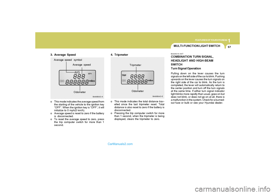
3. Average Speed
B400B04O-E
Tripmeter
B400B03O-A
Average speed Average speed symbol
o This mode indicates the average speed from
the starting of the vehicle to the ignition key
"OFF". When the ignition key is "OFF", it will
initialize to 0 mph(0 km/h).
o Average speed is reset to zero if the battery
is disconnected.
o To reset the average speed to zero, press
the trip computer switch for more than 1
second.
4. Tripmetero This mode indicates the total distance trav-
elled since the last tripmeter reset. Total
distance is also reset to zero if the battery is
disconnected.
o Pressing the trip computer switch for more
than 1 second, when the tripmeter is being
displayed, clears the tripmeter to zero.
Odometer
Odometer
Page 153 of 277
2
DRIVING YOUR HYUNDAI
3
RISK OF ROLLOVER
BEFORE STARTING THE ENGINE
!
!
WARNING:
o The 2WD Santa Fe is not designed for
off-road use. The 4WD Santa Fe is de-
signed primarily for use on paved roads.
However, occasional use in off-highway
conditions such as established unpaved
roads and non-challenging off-road
trails is allowed. The 4WD Santa Fe is not
designed for blazing new trails, chal-
lenging off-road conditions, or unpaved
hill climbing. Exceeding the conditions
that were intended for the vehicle's pri-
mary design may result in injury or death.
o Utility vehicle has a significantly higher
collision rate than other type of vehicles.
C020A01HP-AATBefore you start the engine, you should always:
1. Look around the vehicle to be sure there are
no flat tires, puddles of oil, water or other
indications of possible trouble.
2. After entering the car, check to be sure the
parking brake is engaged.
3. Check that all windows, and lights are clean.
4. Check that the interior and exterior mirrors
are clean and in position.
5. Check your seat, seatback and headrest to
be sure they are in their proper positions.
6. Lock all the doors.
7. Fasten your seat belt and be sure that all
other occupants have fastened theirs.
8. Turn off all lights and accessories that are
not needed.
9. When you turn the ignition switch to "ON",
check that all appropriate warning lights are
operating and that you have sufficient fuel.
10.Check the operation of warning lights and all
bulbs when key is in the "ON" position. o Sports utility vehicles have higher
ground clearance and a narrower track
to make them capable of performing in
a wide variety of off-road applications.
Specific design characteristics give them
a higher center of gravity than ordinary
cars. An advantage of the higher ground
clearance is a better view of the road
allowing you to anticipate problem. They
are not designed for cornering at the
same speeds as conventional 2-wheel
drive vehicles any more than low-slung
sports cars are designed to perform sat-
isfactorily under off-road conditions. If
at all possible, avoid sharp turns or abrupt
maneuvers. As with other vehicles of
this type, failure to operate this vehicle
correctly may result in loss of control or
vehicle rollover.
o In a collision, an unbelted person is
significantly more likely to be seriously
injured or killed than a person wearing a
seatbelt.
WARNING:
C015A01O-AAT
Page 212 of 277
6
Engine Compartment .................................................... 6-2
General Checks ............................................................ 6-4
Checking the Engine Oil ............................................... 6-5
Changing the Oil and Filter ............................................ 6-6
Checking and Changing the Engine Coolant ................ 6-8
Spark Plugs................................................................6-10
Changing the Air Cleaner Filter ...................................6-11
Checking the Transaxle Fluid (Automatic)..................6-13
Checking the Brakes ..................................................6-15
Air Conditioning Care..................................................6-16
Checking Drive Belts ..................................................6-19
Checking and Replacing Fuses..................................6-20
Checking the Battery..................................................6-22
Power Steering Fluid Level .........................................6-23
Replacement of Light Bulbs ........................................6-26
Bulb Wattage ...............................................................6-32
Fuse Panel Description...............................................6-33
DO-IT-YOURSELF MAINTENANCE
6
Page 237 of 277
6
DO-IT-YOURSELF MAINTENANCE
26
REPLACEMENT OF LIGHT BULBS!
G260A02A-AATBefore attempting to replace a light bulb, be sure
the switch is turned to the "OFF" position.
The next paragraph shows how to reach the
light bulbs so they may be changed. Be sure to
replace the burned-out bulb with one of the
same number and wattage rating.
See page 6-32 for the wattage description.
CAUTION:
Keep the lamps out of contact with petro-
leum products, such as oil, gasoline, etc.
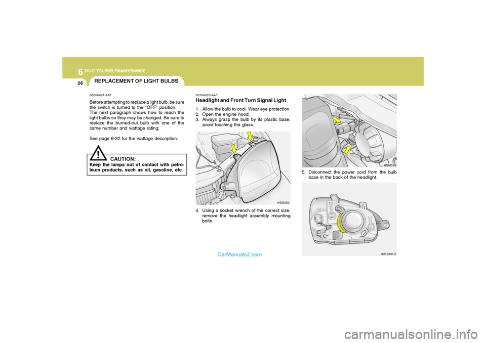
G270A02O-AATHeadlight and Front Turn Signal Light1. Allow the bulb to cool. Wear eye protection.
2. Open the engine hood.
3. Always grasp the bulb by its plastic base,
avoid touching the glass.
4. Using a socket wrench of the correct size,
remove the headlight assembly mounting
bolts.
HSM353
G270A01O
5. Disconnect the power cord from the bulb
base in the back of the headlight.
HSM328
Page 238 of 277
6
DO-IT-YOURSELF MAINTENANCE
27
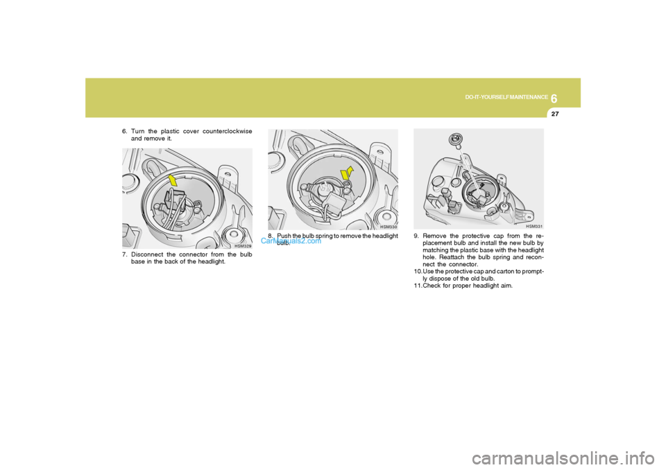
9. Remove the protective cap from the re-
placement bulb and install the new bulb by
matching the plastic base with the headlight
hole. Reattach the bulb spring and recon-
nect the connector.
10.Use the protective cap and carton to prompt-
ly dispose of the old bulb.
11.Check for proper headlight aim.
HSM331
6. Turn the plastic cover counterclockwise
and remove it.
HSM329
7. Disconnect the connector from the bulb
base in the back of the headlight.
HSM330
8. Push the bulb spring to remove the headlight
bulb.
Page 239 of 277
6
DO-IT-YOURSELF MAINTENANCE
28
!
WARNING:
This halogen bulb contains gas under pres-
sure and if impacted could shatter, result-
ing in flying fragments. Always wear eye
protection when servicing the bulb. Protect
the bulb against abrasions or scratches
and against liquids when lighted. Turn the
bulb on only when installing in a headlight.
Replace the headlight if damaged or cracked.
Keep the bulb out of the reach of children
and dispose of the used bulb with care.
G270A03O
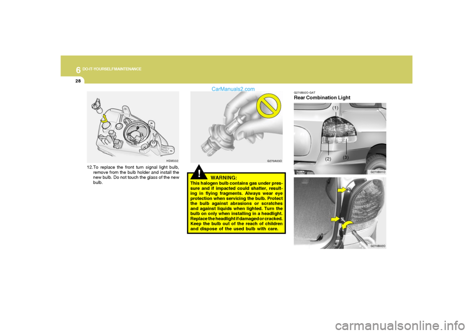
12.To replace the front turn signal light bulb,
remove from the bulb holder and install the
new bulb. Do not touch the glass of the new
bulb.
HSM332
G270B02O-GATRear Combination Light
G270B01O
(3) (1)
(2)
G270B02O
Page 240 of 277
6
DO-IT-YOURSELF MAINTENANCE
29
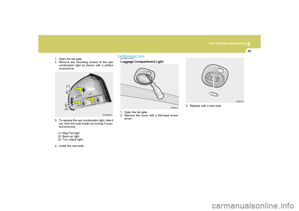
HSM342
3. Replace with a new bulb.
G270C01O-AATLuggage Compartment Light1. Open the tail gate.
2. Remove the cover with a flat-head screw-
driver.
HSM341
1. Open the tail gate.
2. Remove the mounting screws of the rear
combination light as shown with a phillips
screwdriver.
(1)
(2)
(3)
G270B03O
3. To replace the rear combination light, take it
out from the bulb holder by turning it coun-
terclockwise.
(1) Stop/Tail light
(2) Back-up light
(3) Turn signal light
4. Install the new bulb.
Page 241 of 277
6
DO-IT-YOURSELF MAINTENANCE
30
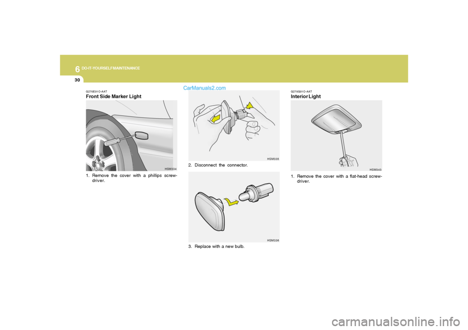
G270E01O-AATFront Side Marker Light1. Remove the cover with a phillips screw-
driver.
HSM334HSM335
HSM336
2. Disconnect the connector.
3. Replace with a new bulb.
G270G01O-AATInterior Light
HSM343
1. Remove the cover with a flat-head screw-
driver.
Page 242 of 277
6
DO-IT-YOURSELF MAINTENANCE
31
G270E02L
HTB284
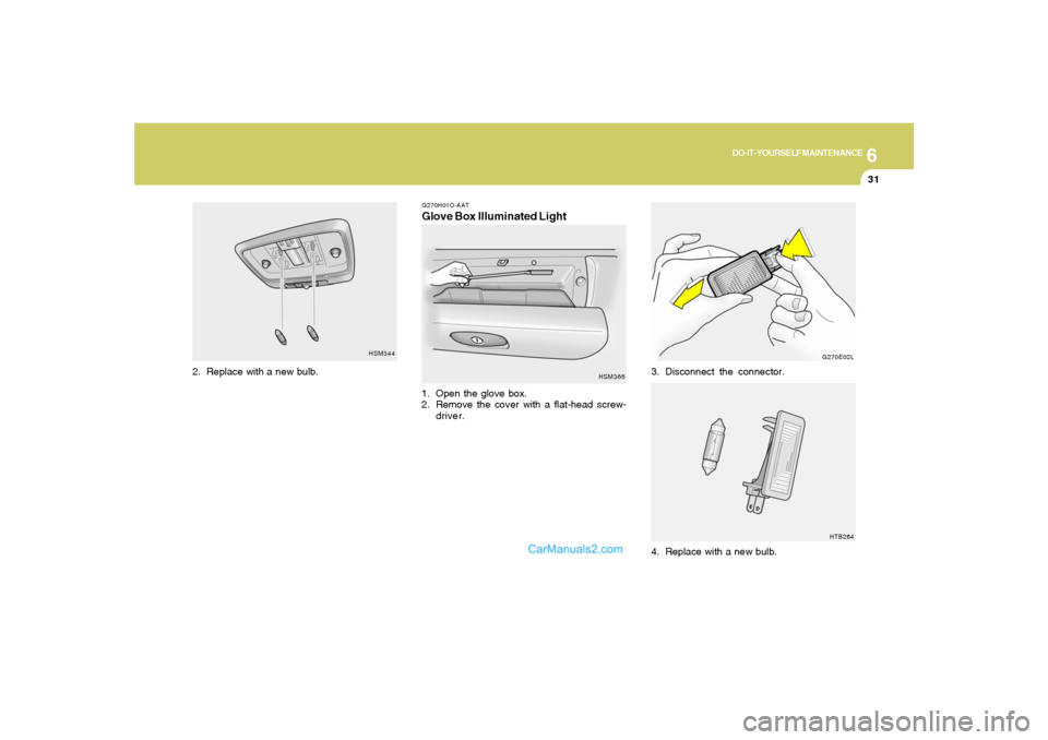
3. Disconnect the connector.
4. Replace with a new bulb.
HSM344
2. Replace with a new bulb.
G270H01O-AATGlove Box Illuminated Light1. Open the glove box.
2. Remove the cover with a flat-head screw-
driver.
HSM366
Page 243 of 277
6
DO-IT-YOURSELF MAINTENANCE
32
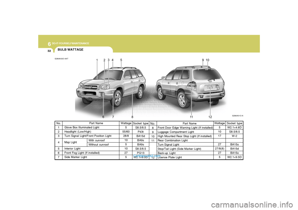
Socket type
S8.5/8.5
P43t
BA15d
BA9s
BA9s
S8.5/8.5
PG13
W2.1×9.5D
Part Name
Front Door Edge Warning Light (If installed)
Luggage Compartment Light
High Mounted Rear Stop Light (If installed)
Rear Combination Light
Turn Signal Light
Stop/Tail Light (Side Marker Light)
Back-up Light
License Plate LightWattage
5
10
17
27
27/8(8)
27
5 No.
1
2
3
4
5
6
7
BULB WATTAGEG280A03O-AAT
G280A01O-A
Part Name
Glove Box Illuminated Light
Headlight (Low/High)
Turn Signal Light/Front Position Light
Map Light
Interior Light
Front Fog Light (If installed)
Side Marker LightWattage
5
55/60
28/8
10
5
10
27
5
No.
With sunroof
Without sunroof8
9
10
11
12
Socket type
W2.1×4.6D
S8.5/8.5
W-2
BA15s
BA15d
BA15s
W2.1×9.5D