load capacity Hyundai Santa Fe 2005 Owner's Manual
[x] Cancel search | Manufacturer: HYUNDAI, Model Year: 2005, Model line: Santa Fe, Model: Hyundai Santa Fe 2005Pages: 277, PDF Size: 10.53 MB
Page 126 of 277
1
FEATURES OF YOUR HYUNDAI
115
B260D04O-AAT1. Playing CDo Insert the CD with the label facing upward.
o Insert the CD to start CD playback, during
radio operation.
o When a disc is in the CD deck, if you press
the CD button, the CD player will begin
playing even if the radio is being used.
o The CD player can be used when the ignition
switch is in either the "ON" or "ACC" position.2. FF/REW ( / )If you want to fast forward or reverse through
the compact disc track, push and hold the FF
( ) or REW ( ) button.
When you release the button, the compact disc
player will resume playing.3. TRACK UP/DOWNo The desired track on the disc currently being
played can be selected using the track
number.
o Press once to skip forward to the beg-
inning of the next track. Press once to
skip back to the beginning of the track.
4. SCAN Buttono Press the SCAN button to playback the first
10 seconds of each track.
o Press the SCAN button again within 10 sec.
when you have reached the desired track.5. REPEAT Buttono To repeat the track you are currently listen-
ing to, press the RPT button. To cancel ,
press again.
o If you do not release RPT operation when the
track ends, it will automatically be replayed.
This process will be continued until you push
the button again.6. EJECT ButtonWhen the EJECT button is pressed with a
CD loaded, the CD will eject.
NOTE:o If the CD does not operate properly or if
the ER2 fault code is displayed, use one
of two methods to reset the CD deck
function.
- Remove the audio fuse for 5 minutes.
Then, reinstall the audio fuse.
- Diconnect the negative terminal of the
battery and wait 5 minutes. Then re-
connect the negative battery terminal.
o To assure proper operation of the unit,
keep the vehicle interior temperature
within a normal range by using the
vehicle's air conditioning or heating
system.
o When replacing the fuse, replace it with
a fuse having the correct capacity.
o The preset station frequencies are all
erased when the car battery is discon-
nected. Therefore, all data will have to be
set again if this should occur.
o Do not add any oil to the rotating parts.
Keep magnets, screwdrivers and other
metallic objects away from the tape
mechanism and head.
Page 154 of 277
2
DRIVING YOUR HYUNDAI
4
!
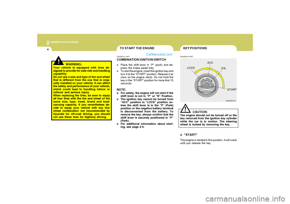
KEY POSITIONS
TO START THE ENGINE
C040A01A-AAT
CAUTION:
The engine should not be turned off or the
key removed from the ignition key cylinder
while the car is in motion. The steering
wheel is locked by removing the key.
C040A01E-1
LOCKACC
ON
START!
C030A01L-AATCOMBINATION IGNITION SWITCHo Place the shift lever in "P" (park) and de-
press the brake pedal fully.
o To start the engine, insert the ignition key and
turn it to the "START" position. Release it as
soon as the engine starts. Do not hold the
key in the "START" position for more that 15
seconds.NOTE:o For safety, the engine will not start if the
shift lever is not in "P" or "N" Position.
o The ignition key cannot be turned from
"ACC" position to "LOCK" position un-
less the shift lever is in the "P" (Park)
position or the negative battery terminal
is disconnected from the battery. To
remove the key, always confirm that the
shift lever is securely positioned in "P"
(Park).
o For additional information about start-
ing, see page 2-5.
o "START"The engine is started in this position. It will crank
until you release the key.
WARNING:
Your vehicle is equipped with tires de-
signed to provide for safe ride and handling
capability.
Do not use a size and type of tire and wheel
that is different from the one that is origi-
nally installed on your vehicle. It can affect
the safety and performance of your vehicle,
which could lead to handling failure or
rollover and serious injury.
When replacing the tires, be sure to equip
all four tires with the tire and wheel of the
same size, type, tread, brand and load-
carrying capacity. If you nevertheless de-
cide to equip your vehicle with any tire/
wheel combination not recommended by
Hyundai for off-road driving, you should
not use these tires for highway driving.
Page 167 of 277
2
DRIVING YOUR HYUNDAI
17
!
(8)The full-time 4WD vehicle cannot be
towed by an ordinary tow truck. Make
sure that the vehicle is towed with all
four wheels raised off the ground.
o Roadside Assistance Program:
Off-roading is not covered. To receive
service, the vehicle must be on a publicly
maintained road.
o If the vehicle is towed with only two
wheels raised off the ground, the 4WD
system could be damaged.
o In unavoidable cases, if the vehicle is
being towed with all four wheels on the
ground, it should only be towed forward.
o While towing, check the following items.
1. The ignition switch is in "ACC" or
"ON".
2. Place the shift lever in neutral (For
Automatic Transaxle, "N" position).
3. Release the parking brake.NOTE:To avoid serious damage to your 4WD ve-
hicle, limit towing to 10 mph and not for
more than 1 mile at ANY TIME.
WARNING:
Your vehicle is equipped with tires de-
signed to provide for safe ride and handling
capability.
Do not use a size and type of tire and wheel
that is different from the one that is origi-
nally installed on your vehicle. It can affect
the safety and performance of your vehicle,
which could lead to handling failure or
rollover and serious injury.
When replacing the tires, be sure to equip
all four tires with the tire and wheel of the
same size, type, tread, brand and load-
carrying capacity. If you nevertheless de-
cide to equip your vehicle with any tire/
wheel combination not recommended by
Hyundai for off-road driving, you should
not use these tires for highway driving.
HSM281
Roll tester(Speedometer)Temporary free roller
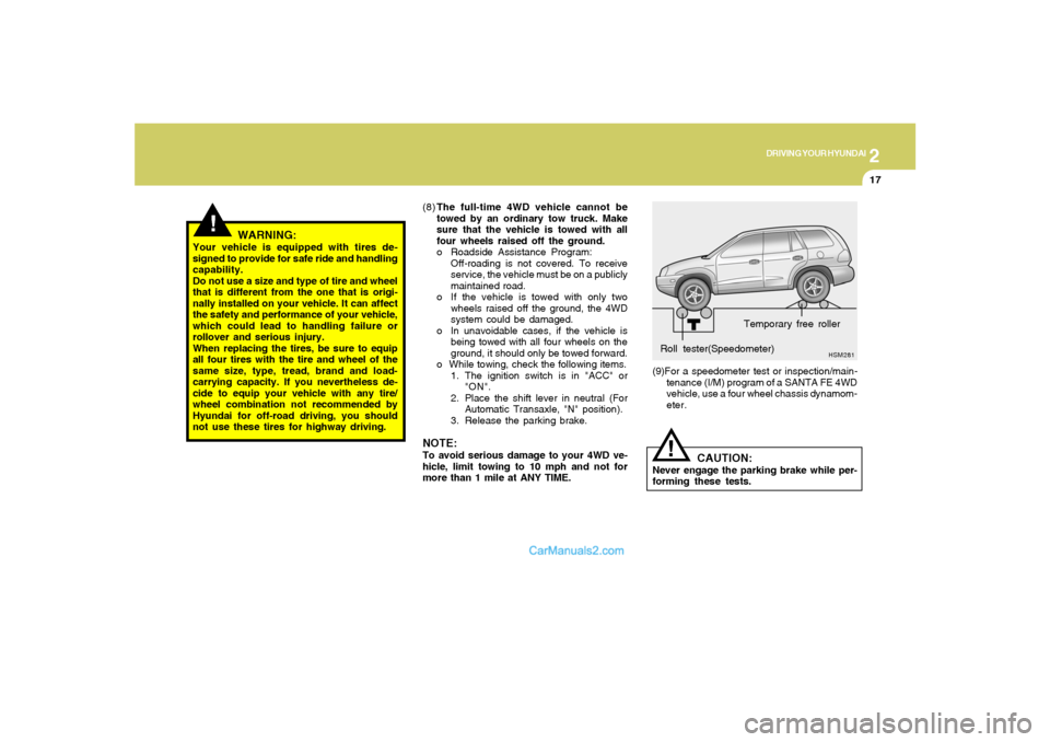
CAUTION:
Never engage the parking brake while per-
forming these tests.
!
(9)For a speedometer test or inspection/main-
tenance (I/M) program of a SANTA FE 4WD
vehicle, use a four wheel chassis dynamom-
eter.
Page 177 of 277
2
DRIVING YOUR HYUNDAI
27
8. If the trailer has electric brakes, start your
vehicle and trailer moving, and then apply the
trailer brake controller by hand to be sure the
brakes are working. This lets you check
your electrical connection at the same time.
9. During your trip, check occasionally to be
sure that the load is secure, and that the
lights and any trailer brakes are still working.
10.Avoid jerky starts, sudden acceleration or
sudden stops.
11.Avoid sharp turns and rapid lane changes.
12.Avoid holding the brake pedal down too long
or too frequently. This could cause the brakes
to overheat, resulting in reduced braking
efficiency.
13.When going down a hill, shift into a lower gear
and use the engine braking effect.
When ascending a long grade, downshift the
transaxle to a lower gear and reduce speed
to reduce chances of engine overloading
and/or overheating.
14.If you have to stop while going uphill, do not
hold the vehicle in place by pressing on the
accelerator. This can cause the automatic
transaxle to overheat. Use the parking brake
or footbrake.
15.If the transaxle shifts frequently while going
up a hill, shift down one gear.
NOTE:When towing check transaxle fluid more
frequently.
CAUTION:
If overheating should occur when towing,
(the temperature gauge reads near red zone),
taking the following action may reduce or
eliminate the problem.
1. Turn off the air conditioner.
2. Reduce highway speed.
3. Select a lower gear when going uphill.
4. While in stop and go traffic, place the
gear selector in park or neutral and idle
the engine at a higher speed.
!
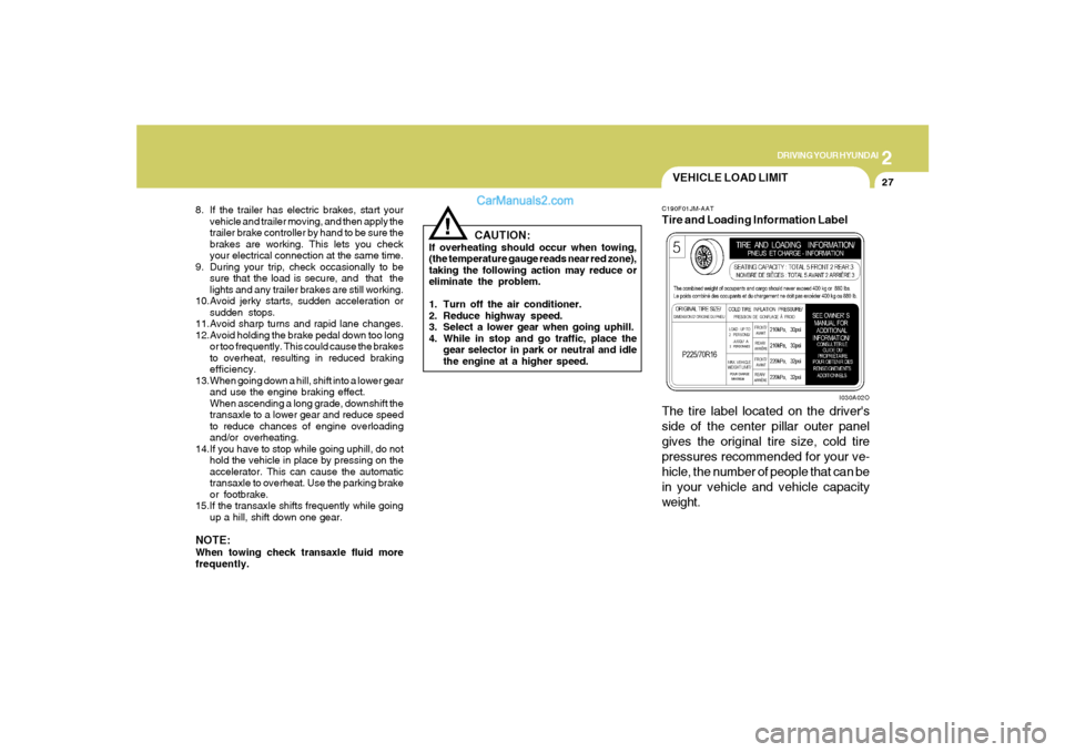
VEHICLE LOAD LIMITC190F01JM-AATTire and Loading Information Label
I030A02O
The tire label located on the driver's
side of the center pillar outer panel
gives the original tire size, cold tire
pressures recommended for your ve-
hicle, the number of people that can be
in your vehicle and vehicle capacity
weight.
Page 178 of 277
2
DRIVING YOUR HYUNDAI
28
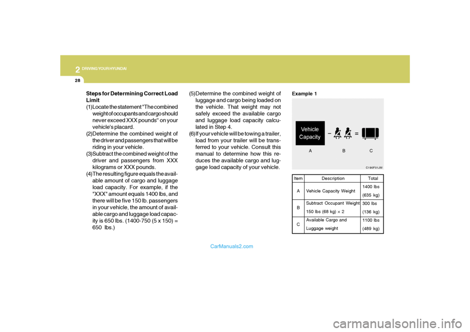
C190F01JMTotal
1400 lbs
(635 kg)
300 lbs
(136 kg)
1100 lbs
(489 kg)
Example 1Item
A
B
CDescription
Vehicle Capacity Weight
Subtract Occupant Weight
150 lbs (68 kg) × 2
Available Cargo and
Luggage weight
ABC
Steps for Determining Correct Load
Limit
(1)Locate the statement "The combined
weight of occupants and cargo should
never exceed XXX pounds'' on your
vehicle's placard.
(2)Determine the combined weight of
the driver and passengers that will be
riding in your vehicle.
(3)Subtract the combined weight of the
driver and passengers from XXX
kilograms or XXX pounds.
(4)The resulting figure equals the avail-
able amount of cargo and luggage
load capacity. For example, if the
"XXX" amount equals 1400 lbs, and
there will be five 150 lb. passengers
in your vehicle, the amount of avail-
able cargo and luggage load capac-
ity is 650 lbs. (1400-750 (5 x 150) =
650 lbs.)(5)Determine the combined weight of
luggage and cargo being loaded on
the vehicle. That weight may not
safely exceed the available cargo
and luggage load capacity calcu-
lated in Step 4.
(6)If your vehicle will be towing a trailer,
load from your trailer will be trans-
ferred to your vehicle. Consult this
manual to determine how this re-
duces the available cargo and lug-
gage load capacity of your vehicle.
Page 179 of 277
2
DRIVING YOUR HYUNDAI
29
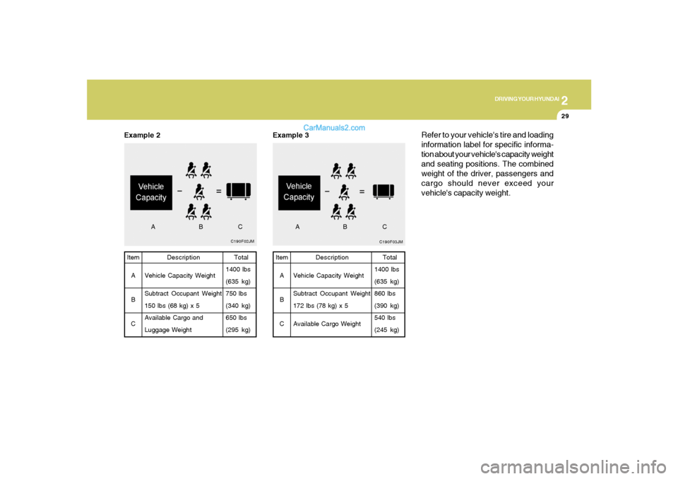
C190F02JM
Example 2
Total
1400 lbs
(635 kg)
750 lbs
(340 kg)
650 lbs
(295 kg) Item
A
B
CDescription
Vehicle Capacity Weight
Subtract Occupant Weight
150 lbs (68 kg) x 5
Available Cargo and
Luggage Weight
ABC
C190F03JMTotal
1400 lbs
(635 kg)
860 lbs
(390 kg)
540 lbs
(245 kg) Item
A
B
CDescription
Vehicle Capacity Weight
Subtract Occupant Weight
172 lbs (78 kg) x 5
Available Cargo Weight
Example 3
ABC
Refer to your vehicle's tire and loading
information label for specific informa-
tion about your vehicle's capacity weight
and seating positions. The combined
weight of the driver, passengers and
cargo should never exceed your
vehicle's capacity weight.
Page 180 of 277
2
DRIVING YOUR HYUNDAI
30
!
!
This label also tells you the maximum
weights that can be supported by the
front and rear axles, called Gross Axle
Weight Rating (GAWR). To find out the
actual loads on your front and rear
axles, you need to go to a weigh station
and weigh your vehicle. Your dealer can
help you with this. Be sure to spread out
your load equally on the left and right
sides of the centerline.
WARNING:
o Never exceed the GVWR for your
vehicle or the GAWR for either the
front or rear axle.
o Do not load your vehicle any
heavier than the GVWR or either
the maximum front or rear GAWR.
If you do, parts on your vehicle
can break, and it can change the
way your vehicle handles. This
could cause you to lose control
and crash. Also, overloading can
shorten the life of your vehicle.
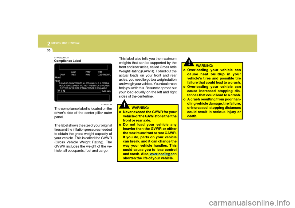
C190G02JM-AATCompliance LabelThe compliance label is located on the
driver's side of the center pillar outer
panel.
The label shows the size of your original
tires and the inflation pressures needed
to obtain the gross weight capacity of
your vehicle. This is called the GVWR
(Gross Vehicle Weight Rating). The
GVWR includes the weight of the ve-
hicle, all occupants, fuel and cargo.
C190G01JM
WARNING:
o Overloading your vehicle can
cause heat buildup in your
vehicle's tires and possible tire
failure that could lead to a crash.
o Overloading your vehicle can
cause increased stopping dis-
tances that could lead to a crash.
o A crash resulting from poor han-
dling vehicle damage, tire failure,
or increased stopping distances
could result in serious injury or
death.
Page 188 of 277
3
WHAT TO DO IN AN EMERGENCY
7
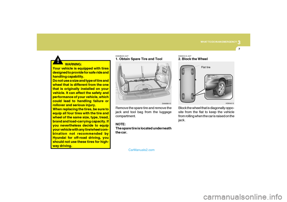
D060C01A-AAT2. Block the Wheel
D060B02O-AAT1. Obtain Spare Tire and Tool
Remove the spare tire and remove the
jack and tool bag from the luggage
compartment.
NOTE:
The spare tire is located underneath
the car.Block the wheel that is diagonally oppo-
site from the flat to keep the vehicle
from rolling when the car is raised on the
jack.
D060B01OHSM4015
Flat tire
!
WARNING:
Your vehicle is equipped with tires
designed to provide for safe ride and
handling capability.
Do not use a size and type of tire and
wheel that is different from the one
that is originally installed on your
vehicle. It can affect the safety and
performance of your vehicle, which
could lead to handling failure or
rollover and serious injury.
When replacing the tires, be sure to
equip all four tires with the tire and
wheel of the same size, type, tread,
brand and load-carrying capacity. If
you nevertheless decide to equip
your vehicle with any tire/wheel com-
bination not recommended by
Hyundai for off-road driving, you
should not use these tires for high-
way driving.
Page 255 of 277
8
CONSUMER INFORMATION, REPORTING SAFETY DEFECTS & BINDING ARBITRATION OF WARRANTY CLAIMS6
6. Maximum load rating
This number indicates the maximum
load in kilograms and pounds that
can be carried by the tire. When
replacing the tires on the vehicle,
always use a tire that has the same
load rating as the factory installed
tire.
7. Uniform Tire Quality Grading
(UTQG):
Tire manufacturers are required to
grade tires based on three perfor-
mance factors: treadwear, traction
and temperature resistance. For more
information, see Uniform Tire Qual-
ity Grading on page 8-13.
I030D01JM-AATTIRE TERMINOLOGY AND DEFINI-
TIONS
Air Pressure: The amount of air inside
the tire pressing outward on the tire. Air
pressure is expressed in pounds per
square inch (psi) or kilopascal (kPa).
Accessory Weight: This means the
combined weight of optional accesso-
ries. Some examples of optional ac-
cessories are, automatic transmission,
power seats, and air conditioning.
Aspect Ratio: The relationship of a
tire's height to its width.
Belt: A rubber coated layer of cords that
is located between the plies and the
tread. Cords may be made from steel or
other reinforcing materials.
Bead: The tire bead contains steel
wires wrapped by steel cords that hold
the tire onto the rim.
Bias Ply Tire: A pneumatic tire in which
the plies are laid at alternate angles
less than 90 degrees to the centerline of
the tread.Cold Tire Pressure: The amount of air
pressure in a tire, measured in pounds
per square inch (psi) or kilopascals
(kPa) before a tire has built up heat from
driving.
Curb Weight: This means the weight of
a motor vehicle with standard and op-
tional equipment including the maxi-
mum capacity of fuel, oil and coolant,
but without passengers and cargo.
DOT Markings: A code molded into the
sidewall of a tire signifying that the tire
is in compliance with the U.S. Depart-
ment of Transportation motor vehicle
safety standards. The DOT code in-
cludes the Tire Identification Number
(TIN), an alphanumeric designator which
can also identify the tire manufacturer,
production plant, brand and date of
production.
GVWR: Gross Vehicle Weight Rating
GAWR FRT: Gross Axle Weight Rating
for the front Axle.
GAWR RR: Gross Axle Weight Rating
for the rear axle.
Page 256 of 277
8
CONSUMER INFORMATION, REPORTING SAFETY DEFECTS & BINDING ARBITRATION OF WARRANTY CLAIMS
7
Intended Outboard Sidewall: The side
of an asymmetrical tire, that must al-
ways face outward when mounted on a
vehicle.
Kilopascal (kPa): The metric unit for
air pressure.
Load Index: An assigned number rang-
ing from 1 to 279 that corresponds to
the load carrying capacity of a tire.
Maximum Inflation Pressure: The
maximum air pressure to which a cold
tire may be inflated. The maximum air
pressure is molded onto the sidewall.
Maximum Load Rating: The load rat-
ing for a tire at the maximum permis-
sible inflation pressure for that tire.
Maximum Loaded Vehicle Weight:
The sum of curb weight; accessory
weight; vehicle capacity weight; and
production options weight.
Normal Occupant Weight: The num-
ber of occupants a vehicle is designed
to seat multiplied by 150 pounds (68
kg).Occupant Distribution: Designated
seating positions.
Outward Facing Sidewall: The side of
an asymmetrical tire that has a particu-
lar side that faces outward when
mounted on a vehicle. The side of the
tire that contains a whitewall, bears
white lettering or bears manufacturer,
brand and or model name molding that
is higher or deeper than the same mold-
ings on the other sidewall of the tire.
Passenger (P-Metric) Tire: A tire used
on passenger cars and some light duty
trucks and multipurpose vehicles.
Recommended Inflation Pressure:
Vehicle manufacturer's recommended
tire inflation pressure as shown on the
tire placard.
Radial Ply tire: A pneumatic tire in
which the ply cords that extend to the
beads are laid at 90 degrees to the
centerline of the tread.
Rim: A metal support for a tire upon
which the tire beads are seated.Sidewall: The portion of a tire between
the tread and the bead.
Speed Rating: An alphanumeric code
assigned to a tire indicating the maxi-
mum speed at which a tire can operate.
Traction: The friction between the tire
and the road surface. The amount of
grip provided.
Tread: The portion of a tire that comes
into contact with the road.
Treadwear Indicators: Narrow bands,
sometimes called "wear bars," that show
across the tread of a tire when only 2/32
inch of tread remains.
UTQGS: Uniform Tire Quality Grading
Standards, a tire information system
that provides consumers with ratings
for a tire's traction, temperature and
treadwear. Ratings are determined by
tire manufacturers using government
testing procedures. The ratings are
molded into the sidewall of the tire.