engine HYUNDAI SANTA FE 2021 Owners Manual
[x] Cancel search | Manufacturer: HYUNDAI, Model Year: 2021, Model line: SANTA FE, Model: HYUNDAI SANTA FE 2021Pages: 636, PDF Size: 81.2 MB
Page 598 of 636
![HYUNDAI SANTA FE 2021 Owners Manual Maintenance
9-48
Engine compartment fuse panel (Engine room junction block)
Type Fuse NameFuse
Rating Circuit Protected
MULTI
FUSE 1 (10P) COOLING FAN1
80A
[BLDC 600W] Cooling Fan Controller
COOLIN HYUNDAI SANTA FE 2021 Owners Manual Maintenance
9-48
Engine compartment fuse panel (Engine room junction block)
Type Fuse NameFuse
Rating Circuit Protected
MULTI
FUSE 1 (10P) COOLING FAN1
80A
[BLDC 600W] Cooling Fan Controller
COOLIN](/img/35/41163/w960_41163-597.png)
Maintenance
9-48
Engine compartment fuse panel (Engine room junction block)
Type Fuse NameFuse
Rating Circuit Protected
MULTI
FUSE 1 (10P) COOLING FAN1
80A
[BLDC 600W] Cooling Fan Controller
COOLING FAN2 60A
[BLDC 400W] Cooling Fan Controller
B+4 50AICU Junction Block (Fuse - MODULE8,
SUNROOF1, AMP, P/WINDOW RH, S/HEATER
DRV/PASS)
B+2 50AICU Junction Block (IPS 8 SPOC+/IPS 10/IPS 11/
IPS 13/IPS 14/IPS 15)
B+3 50AICU Junction Block (Fuse - E-SHIFTER1, P/
SEAT (DRV, P/SEAT (PASS), P/WINDOW LH, RR
SEAT(LH))
BLOWER 40A
Blower Relay
IG2 40A
Start Relay, PCB Block (PDM (IG2) Relay)
ABS 2 30A
ESC Module
MULTI
FUSE 2 (10P) MDPS
100A MDPS Unit
ABS 3 60A
ESC Module
B+6 60A
PCB Block (B+)
DCT 60A
TCM
E-CVVT1 50A
PCB Block (E-CVVT Relay)
REAR HEATED 40A
Rear Heated Relay
INVERTER 40A
AC Inverter Module
E-SHIFTER 1 40A
SCU
FUSE HEATED
MIRROR 10A
Rear Heated Relay, Driver/Passenger Outside
Mirror, Front A/C Control Module
E-CVVT3 20A
PCM, PCB Block (E-CVVT Relay)
E-CVVT2 20A
PCM, PCB Block (E-CVVT Relay)
A/C2 10A
Blower Relay, Front A/C Control Module
VACUUM PUMP2 10A
ESC Module, Vacuum Pump Relay, Vacuum Pump
B+5 50AICU Junction Block (Fuse - DOOR LOCK,
IBU1, IBU2, BRAKE SWITCH, CHILD LOCK, RR
SEAT(RH), SUNROOF2)
EOP2 60A
[G4KP] Electronic Oil Pump
Page 599 of 636
09
9-49
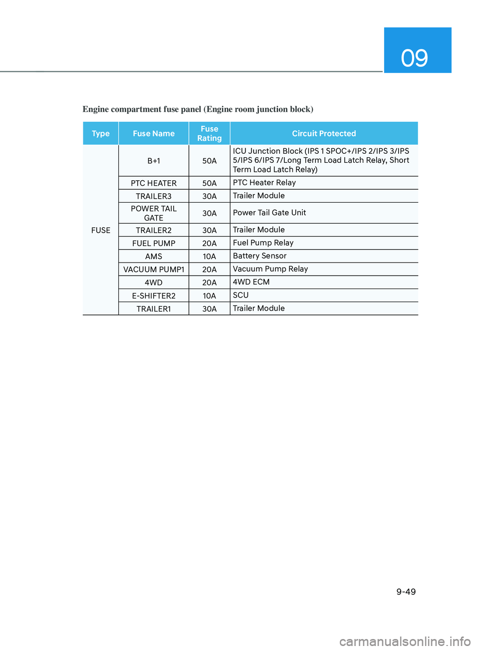
Engine compartment fuse panel (Engine room junction block)
Type Fuse NameFuse
Rating Circuit Protected
FUSE B+1
50AICU Junction Block (IPS 1 SPOC+/IPS 2/IPS 3/IPS
5/IPS 6/IPS 7/Long Term Load Latch Relay, Short
Term Load Latch Relay)
PTC HEATER 50APTC Heater Relay
TRAILER3 30ATrailer Module
POWER TAIL GATE 30A
Power Tail Gate Unit
TRAILER2 30ATrailer Module
FUEL PUMP 20AFuel Pump Relay
AMS 10ABattery Sensor
VACUUM PUMP1 20AVacuum Pump Relay
4WD 20A4WD ECM
E-SHIFTER2 10ASCU
TRAILER1 30ATrailer Module
Page 600 of 636
Maintenance
9-50
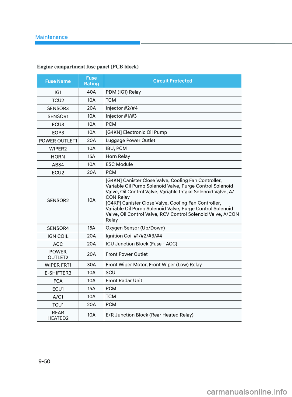
Engine compartment fuse panel (PCB block)
Fuse NameFuse
Rating Circuit Protected
IG1 40A
PDM (IG1) Relay
TCU2 10A
TCM
SENSOR3 20A
Injector #2/#4
SENSOR1 10A
Injector #1/#3
ECU3 10A
PCM
EOP3 10A
[G4KN] Electronic Oil Pump
POWER OUTLET1 20A
Luggage Power Outlet
WIPER2 10A
IBU, PCM
HORN 15A Horn Relay
ABS4 10A
ESC Module
ECU2 20A
PCM
SENSOR2 10A[G4KN] Canister Close Valve, Cooling Fan Controller,
Variable Oil Pump Solenoid Valve, Purge Control Solenoid
Valve, Oil Control Valve, Variable Intake Solenoid Valve, A/
CON Relay
[G4KP] Canister Close Valve, Cooling Fan Controller,
Variable Oil Pump Solenoid Valve, Purge Control Solenoid
Valve, Oil Control Valve, RCV Control Solenoid Valve, A/CON
Relay
SENSOR4 15A Oxygen Sensor (Up/Down)
IGN COIL 20A
Ignition Coil #1/#2/#3/#4
ACC 20A
ICU Junction Block (Fuse - ACC)
POWER
OUTLET2 20A
Front Power Outlet
WIPER FRT1 30A
Front Wiper Motor, Front Wiper (Low) Relay
E-SHIFTER3 10A
SCU
FCA 10A
Front Radar Unit
ECU1 15A PCM
A/C1 10A
TCM
TCU1 20A
PCM
REAR
HEATED2 10A
E/R Junction Block (Rear Heated Relay)
Page 601 of 636
09
9-51
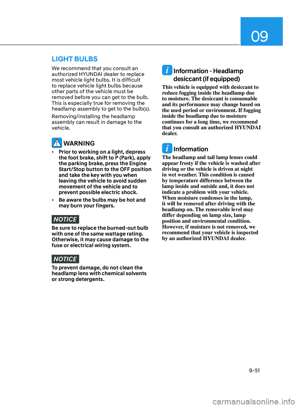
We recommend that you consult an
authorized HYUNDAI dealer to replace
most vehicle light bulbs. It is difficult
to replace vehicle light bulbs because
other parts of the vehicle must be
removed before you can get to the bulb.
This is especially true for removing the
headlamp assembly to get to the bulb(s).
Removing/installing the headlamp
assembly can result in damage to the
vehicle.
WARNING
• Prior to working on a light, depress
the foot brake, shift to P (Park), apply
the parking brake, press the Engine
Start/Stop button to the OFF position
and take the key with you when
leaving the vehicle to avoid sudden
movement of the vehicle and to
prevent possible electric shock.
• Be aware the bulbs may be hot and
may burn your fingers.
NOTICE
Be sure to replace the burned-out bulb
with one of the same wattage rating.
Otherwise, it may cause damage to the
fuse or electrical wiring system.
NOTICE
To prevent damage, do not clean the
headlamp lens with chemical solvents
or strong detergents.
Information - Headlamp
desiccant (if equipped)
This vehicle is equipped with desiccant to
reduce fogging inside the headlamp due
to moisture. The desiccant is consumable
and its performance may change based on
the used period or environment. If fogging
inside the headlamp due to moisture
continues for a long time, we recommend
that you consult an authorized HYUNDAI
dealer.
Information
The headlamp and tail lamp lenses could
appear frosty if the vehicle is washed after
driving or the vehicle is driven at night
in wet weather. This condition is caused
by temperature difference between the
lamp inside and outside and, it does not
indicate a problem with your vehicle.
When moisture condenses in the lamp,
it will be removed after driving with the
headlamp on. The removable level may
differ depending on lamp size, lamp
position and environmental condition.
However, if moisture is not removed, we
recommend that your vehicle is inspected
by an authorized HYUNDAI dealer.
LIGHT BULBS
Page 604 of 636
Maintenance
9-54
• Always handle them carefully, and
avoid scratches and abrasions. If
the bulbs are lit, avoid contact with
liquids.
• Never touch the glass with bare
hands. Residual oil may cause the
bulb to overheat and burst when lit.
• A bulb should be operated only when
installed in a headlamp.
• If a bulb becomes damaged or
cracked, replace it immediately and
carefully dispose of it.
Lamps
If the LED lamp does not operate, we
recommend that you have the vehicle
checked by an authorized HYUNDAI
dealer.
Side repeater lamp replacement
OTM090023
If the LED lamp (1) does not operate,
we recommend that the system be
inspected by an authorized HYUNDAI
dealer.
The LED lamps cannot be replaced as
a single unit because it is an integrated
unit. The LED lamps has to be replaced
with the unit.
A skilled technician should check or
repair the LED lamp, for it may damage
related parts of the vehicle.
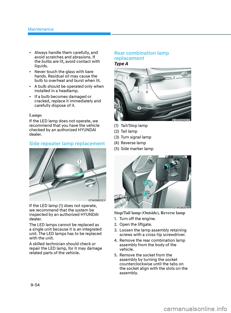
Rear combination lamp
replacement
Type A
OTMA090021
(1) Tail/Stop lamp
(2)
Tail lamp
(3
)
Turn signal lamp
(4
)
Re
verse lamp
(5)
Side marker lamp
OTM090044
Stop/Tail lamp (Outside), Reverse lamp
1.
Turn o
ff the engine.
2.
Open the liftga
te.
3.
Loosen the lamp assembly r
etaining
screws with a cross-tip screwdriver.
4.
Remo
ve the rear combination lamp
assembly from the body of the
vehicle.
5.
Remo
ve the socket from the
assembly by turning the socket
counterclockwise until the tabs on
the socket align with the slots on the
assembly.
Page 605 of 636
09
9-55
OTM090045L
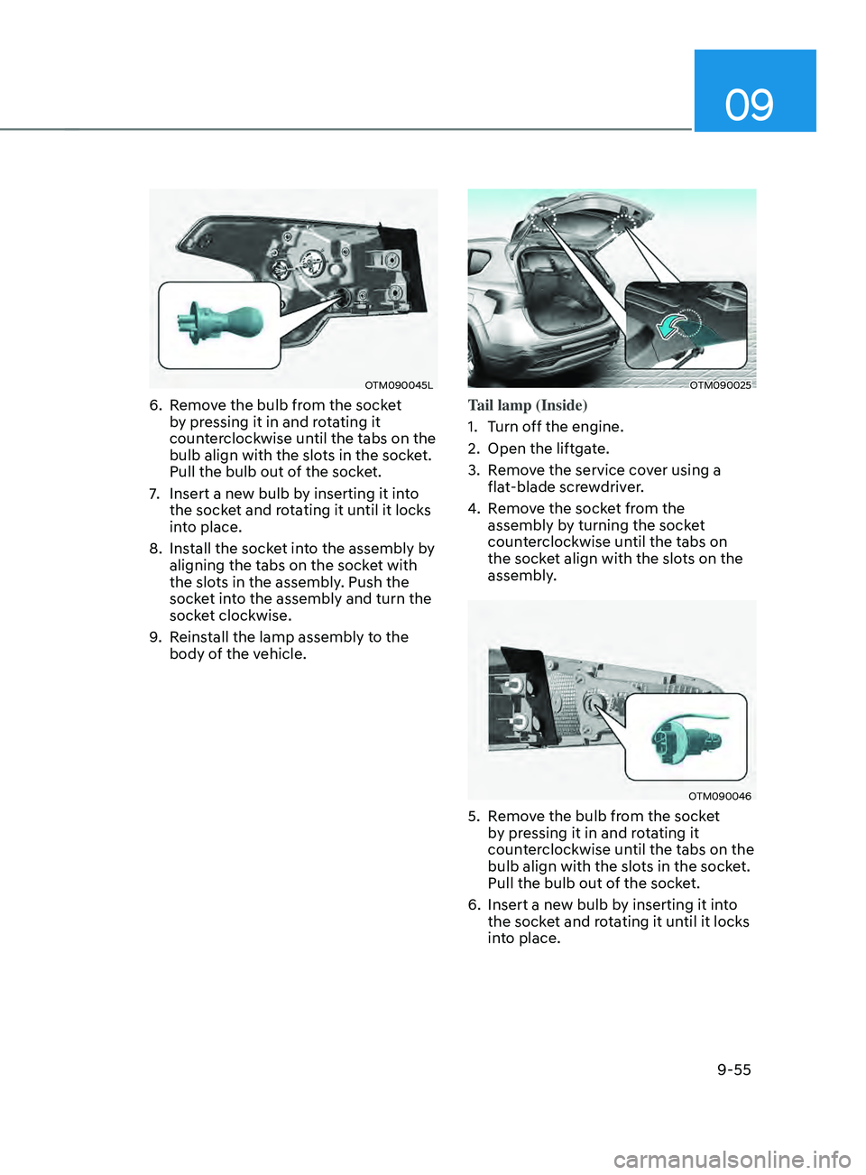
6. Remove the bulb from the socket
by pressing it in and rotating it
counterclockwise until the tabs on the
bulb align with the slots in the socket.
Pull the bulb out of the socket.
7.
Insert a new bulb b
y inserting it into
the socket and rotating it until it locks
into place.
8.
Install the sock
et into the assembly by
aligning the tabs on the socket with
the slots in the assembly. Push the
socket into the assembly and turn the
socket clockwise.
9.
Reins
tall the lamp assembly to the
body of the vehicle.
OTM090025
Tail lamp (Inside)
1.
Turn o
ff the engine.
2.
Open the liftga
te.
3.
Remo
ve the service cover using a
flat-blade screwdriver.
4.
Remo
ve the socket from the
assembly by turning the socket
counterclockwise until the tabs on
the socket align with the slots on the
assembly.
OTM090046
5. Remove the bulb from the socket
b y pressing it in and rotating it
counterclockwise until the tabs on the
bulb align with the slots in the socket.
Pull the bulb out of the socket.
6.
Insert a new bulb b
y inserting it into
the socket and rotating it until it locks
into place.
Page 606 of 636

Maintenance
9-56
7. Install the socket into the assembly by
aligning the tabs on the socket with
the slots in the assembly. Push the
socket into the assembly and turn the
socket clockwise.
8.
Reins
tall the lamp assembly to the
body of the vehicle.
Turn signal lamp
If these lamps do not operate, we
recommend that you have the vehicle
checked by an authorized HYUNDAI
dealer.
Type B
OTMA090022
(1) Tail/Stop lamp
(2)
St
op lamp
(3)
Turn signal lamp
(4
)
Re
verse lamp
(5)
Side marker lamp
OTM090044
Reverse lamp
1.
Turn o
ff the engine.
2.
Open the liftga
te.
3.
Loosen the lamp assembly r
etaining
screws with a cross-tip screwdriver.
4.
Remo
ve the rear combination lamp
assembly from the body of the
vehicle.
5.
Remo
ve the socket from the
assembly by turning the socket
counterclockwise until the tabs on
the socket align with the slots on the
assembly.
Page 611 of 636
09
9-61
NOTICE
• Do not use strong soap, chemical
detergents or hot water, and do not
wash the vehicle in direct sunlight
or when the body of the vehicle is
warm.
• Be careful when washing the side
windows of your vehicle.
• Especially, with high-pressure water,
water may leak through the windows
and wet the interior.
• To prevent damage to the plastic
parts, do not clean with chemical
solvents or strong detergents.
NOTICE
OTM090031
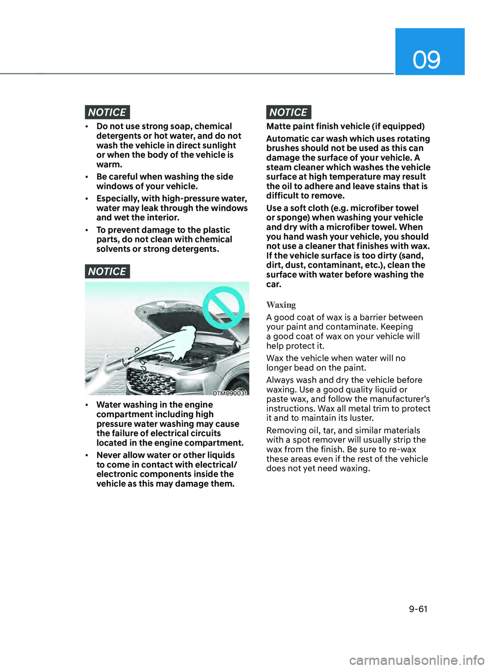
• Water washing in the engine
compartment including high
pressure water washing may cause
the failure of electrical circuits
located in the engine compartment.
• Never allow water or other liquids
to come in contact with electrical/
electronic components inside the
vehicle as this may damage them.
NOTICE
Matte paint finish vehicle (if equipped)
Automatic car wash which uses rotating
brushes should not be used as this can
damage the surface of your vehicle. A
steam cleaner which washes the vehicle
surface at high temperature may result
the oil to adhere and leave stains that is
difficult to remove.
Use a soft cloth (e.g. microfiber towel
or sponge) when washing your vehicle
and dry with a microfiber towel. When
you hand wash your vehicle, you should
not use a cleaner that finishes with wax.
If the vehicle surface is too dirty (sand,
dirt, dust, contaminant, etc.), clean the
surface with water before washing the
car.
Waxing
A good coat of wax is a barrier between
your paint and contaminate. Keeping
a good coat of wax on your vehicle will
help protect it.
Wax the vehicle when water will no
longer bead on the paint.
Always wash and dry the vehicle before
waxing. Use a good quality liquid or
paste wax, and follow the manufacturer’s
instructions. Wax all metal trim to protect
it and to maintain its luster.
Removing oil, tar, and similar materials
with a spot remover will usually strip the
wax from the finish. Be sure to re-wax
these areas even if the rest of the vehicle
does not yet need waxing.
Page 619 of 636

09
9-69
The emission control system of your
vehicle is covered by a written limited
warranty. Please see the warranty
information contained in the Service
Passport in your vehicle.
Your vehicle is equipped with an
emission control system to meet all
applicable emission regulations. There
are three emission control systems, as
follows.
(1)
Crank
case emission control system
(2)
Ev
aporative emission control system
(3)
Exhaust emission con
trol system
In order to ensure the proper function
of the emission control systems, it
is recommended that you have your
vehicle inspected and maintained
by an authorized HYUNDAI dealer in
accordance with the maintenance
schedule in this manual.
NOTICE
For the Inspection and Maintenance
Test (with Electronic Stability Control
(ESC) system)
• To prevent the vehicle from misfiring
during dynamometer testing, turn
the Electronic Stability Control
(ESC) system off by pressing the ESC
switch (ESC OFF light illuminated).
• After dynamometer testing is
completed, turn the ESC system back
on by pressing the ESC switch again.
1. Crankcase emission control
sy
stem
The positive crankcase ventilation system
is employed to prevent air pollution
caused by blow-by gases being emitted
from the crankcase. This system supplies
fresh filtered air to the crankcase through
the air intake hose. Inside the crankcase,
the fresh air mixes with blow-by gases,
which then pass through the PCV valve
into the induction system.
2. Evaporative emission control
system
The Evaporative Emission Control System
is designed to prevent fuel vapors from
escaping into the atmosphere.
Canister
Fuel vapors generated inside the fuel
tank are absorbed and stored in the
onboard canister. When the engine is
running, the fuel vapors absorbed in the
canister are drawn into the surge tank
through the purge control solenoid valve.
Purge Control Solenoid Valve (PCSV)
The purge control solenoid valve
is controlled by the Engine Control
Module (ECM); when the engine coolant
temperature is low during idling, the
PCSV closes so that evaporated fuel
is not taken into the engine. After the
engine warms-up during ordinary
driving, the PCSV opens to introduce
evaporated fuel to the engine.
EMISSION CONTROL SYSTEM
Page 620 of 636
Maintenance
9-70
3. Exhaust emission control
system
The Exhaust Emission Control System is
a highly effective system which controls
exhaust emissions while maintaining
good vehicle performance.
When the engine starts or fails to start,
excessive attempts to restart the engine
may cause damage to the emission
system.
Engine exhaust (carbon monoxide)
precautions
• Carbon monoxide can be present
with other exhaust fumes. If you smell
exhaust fumes of any kind in your
vehicle, drive with all the windows
fully open. Have your vehicle checked
and repaired immediately.
WARNING
Engine exhaust gases contain carbon
monoxide (CO). Though colorless and
odorless, it is dangerous and could be
lethal if inhaled. Follow the instructions
on this page to avoid CO poisoning.
WARNING
CALIFORNIA PROPOSITION 65
WARNING
Engine exhaust and a wide variety of
automobile components and parts,
including components found in the
interior furnishings in a vehicle, contain
or emit chemicals known to the State
of California to cause cancer and
birth defects and reproductive harm.
In addition, certain fluids contained
in vehicles and certain products of
component wear contain or emit
chemicals known to the State of
California to cause cancer and birth
defects or other reproductive harm. •
Do not operate the engine in confined
or closed areas (such as garages) any
more than what is necessary to move
the vehicle in or out of the area.
• When the vehicle is stopped in an
open area for more than a short time
with the engine running, adjust the
ventilation system (as needed) to draw
outside air into the vehicle.
• Never sit in a parked or stopped
vehicle for any extended time with the
engine running.
• When the engine stalls or fails to
start, excessive attempts to restart
the engine may cause damage to the
emission control system.
Operating precautions for catalytic
converters (if equipped)
WARNING
The exhaust system and catalytic
converter are very hot during and
immediately after the engine has been
running. To avoid SERIOUS INJURY or
DEATH:
• Do not park, idle, or drive the vehicle
over or near flammable objects, such
as grass, vegetation, paper, leaves,
etc. A hot exhaust system can ignite
flammable items under your vehicle.
• Keep away from the exhaust system
and catalytic converter or you may
get burned.
Also, do not remove the heat sink
around the exhaust system, do not
seal the bottom of the vehicle, and
do not coat the vehicle for corrosion
control. It may present a fire risk
under certain conditions.