display HYUNDAI SANTA FE HYBRID 2021 Owners Manual
[x] Cancel search | Manufacturer: HYUNDAI, Model Year: 2021, Model line: SANTA FE HYBRID, Model: HYUNDAI SANTA FE HYBRID 2021Pages: 598, PDF Size: 66.6 MB
Page 18 of 598

Foreword / Hybrid System Overview
1-14
LCD display messages
Ready to drive
OTMHQ010019N
This message is displayed when the
vehicle is ready to be driven.
Check regenerative brakes
OTMHQ010020N
This message is displayed when
the brake performance is low or the
regenerative brake does not work
properly due to a failure in the brake
system.
If this occurs, it may take longer for the
brake pedal to operate and the braking
distance may become longer.
Stop vehicle and check regenerative
brakes
OTMHQ010021N
This message is displayed when a failure
occurs in the brake system.
If this occurs, park the vehicle in a
safe location and we recommend that
you tow your vehicle to the nearest
authorized HYUNDAI dealer and have the
vehicle inspected.
Check Hybrid system
OTMHQ010022N
This message is displayed when there is a
problem with the hybrid control system.
Refrain from driving when the warning
message is displayed.
If this occurs, we recommend that
you have the vehicle inspected by an
authorized HYUNDAI dealer.
Page 19 of 598

01
1-15
Check Hybrid system. Stop safely
OTMHQ010023N
This message is displayed when there
is a problem with the hybrid control
system. The “
” indicator will blink
and a warning chime will sound until the
problem is solved. Refrain from driving
when the warning message is displayed.
If this occurs, we recommend that
you have the vehicle inspected by an
authorized HYUNDAI dealer.
Check Hybrid system. Do not start
engine
OTMHQ010024N
This message is displayed when the
hybrid battery power (SOC) level is low.
A warning chime will sound until the
problem is solved. Refrain from driving
when the warning message is displayed.
If this occurs, we recommend that
you have the vehicle inspected by an
authorized HYUNDAI dealer.
Stop safely and check power supply
OTMHQ010025N
This message is displayed when a failure
occurs in the power supply system.
If this occurs, park the vehicle in a safe
location and tow your vehicle to the
nearest authorized HYUNDAI dealer and
have the vehicle inspected.
Check virtual engine sound system
OTMHQ010026N
This message is displayed when there is
a problem with the Virtual Engine Sound
System (VESS).
If this occurs, we recommend that
you have the vehicle inspected by an
authorized HYUNDAI dealer.
Page 20 of 598

Foreword / Hybrid System Overview
1-16
Refill inverter coolant
OTMHQ010028N
This message is displayed when the
inverter coolant is nearly empty.
You should refill the inverter coolant.
Park with engine On to charge
battery
OTMHQ010029N
This message is displayed when the
hybrid battery power (SOC) level is low.
If this occurs, park the vehicle in a safe
location and wait until the hybrid battery
is charged.
Start engine to avoid battery
discharge
OTMHQ010030N
This message is displayed to inform the
driver the 12V battery may be discharged
if the ignition switch is in ON position
(without the
indicator ON).
Set the vehicle to the ready () mode
to prevent the 12V battery from being
discharged.
Page 34 of 598

2-6
Vehicle Information, Consumer Information and Reporting Safety Defects
1. Lighting control lever ............................5-78
2. Wiper and washer control lever...........5-89
3. Voice recognition button ....................5-125
4. Bluetooth® hands-free
phone button
.......................................5-126
5. LCD display control ..............................4-28
6. Driving Assist button .............................7-54
7. Vehicle Distance button ........................7-54
INSTRUMENT PANEL OVERVIEW (II)
The actual shape may differ from the illustration.
OTM010005
Page 41 of 598

02
2-13
Recommended SAE viscosity number
CAUTION
Always be sure to clean the area around any filler plug, drain plug, or dipstick before
checking or draining any lubricant. This is especially important in dusty or sandy
areas and when the vehicle is used on unpaved roads. Cleaning the plug and dipstick
areas will prevent dirt and grit from entering the engine and other mechanisms that
could be damaged.
Engine oil viscosity (thickness) has an effect on fuel economy and cold weather
operating (engine start and engine oil flowability). Lower viscosity engine oils can
provide better fuel economy and cold weather performance, however, higher viscosity
engine oils are required for satisfactory lubrication in hot weather. Using oils of any
viscosity other than those recommended could result in engine damage.
When choosing an oil, consider the range of temperature your vehicle will be operated
in before the next oil change. Proceed to select the recommended oil viscosity from
the chart.
Temperature Range for SAE Viscosity Numbers
Temperature °C
-30 -20-10 010 20 30 4050
(°F) -10020 40 60 80 100120
Smartstream G 1.6 T-GDi HEV
0W-20 0W-20
An engine oil displaying this API Certification Mark conforms to the international Lubricant Specification Advisory Committee
(ILSAC). It is recommended to only use engine oils that uphold
this API Certification Mark.
Page 68 of 598
03
3-23
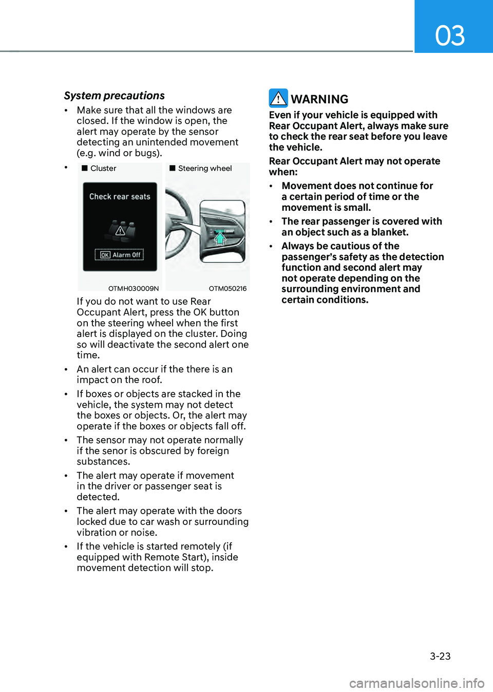
System precautions
• Make sure that all the windows are
closed. If the window is open, the
alert may operate by the sensor
detecting an unintended movement
(e.g. wind or bugs).
• „„Cluster„„Steering wheel
OTMH030009NOTM050216
If you do not want to use Rear
Occupant Alert, press the OK button
on the steering wheel when the first
alert is displayed on the cluster. Doing
so will deactivate the second alert one
time.
• An alert can occur if the there is an
impact on the roof.
• If boxes or objects are stacked in the
vehicle, the system may not detect
the boxes or objects. Or, the alert may
operate if the boxes or objects fall off.
• The sensor may not operate normally
if the senor is obscured by foreign
substances.
• The alert may operate if movement
in the driver or passenger seat is
detected.
• The alert may operate with the doors
locked due to car wash or surrounding
vibration or noise.
• If the vehicle is started remotely (if
equipped with Remote Start), inside
movement detection will stop.
WARNING
Even if your vehicle is equipped with
Rear Occupant Alert, always make sure
to check the rear seat before you leave
the vehicle.
Rear Occupant Alert may not operate
when:
• Movement does not continue for
a certain period of time or the
movement is small.
• The rear passenger is covered with
an object such as a blanket.
• Always be cautious of the
passenger’s safety as the detection
function and second alert may
not operate depending on the
surrounding environment and
certain conditions.
Page 96 of 598
 Driver's front air bag module
(2) Passenger's front air bag module
(3) Side air ba")
03
3-51
How does the air bags system
operate?
OTMH030008N
The SRS consists of the following
components:
(1) Driver's front air bag module
(2) Passenger's front air bag module
(3) Side air bag modules
(4) Curtain air bag modules
(5) Retractor pre-tensioner
(6) Air bag warning light
(7) SRS control module (SRSCM)/
Rollover sensor
(8) Front impact sensors
(9) Side impact sensors
(10) Side pressure sensors
(11) Seat belt buckle sensor
(12) Emergency fastening device system
(13) Occupant classification system
The SRSCM continually monitors all SRS
components while the ignition switch
is ON to determine if a crash impact
is severe enough to require air bag
deployment or pre-tensioner seat belt
deployment.
SRS warning light
The SRS (Supplemental Restraint System)
air bag warning light on the instrument
panel displays the air bag symbol
depicted in the illustration. The system
checks the air bag electrical system for
malfunctions. The light indicates that
there is a potential problem with your
air bag system, which could include
your side and/or curtain air bags used
for rollover protection (if equipped with
rollover sensor).
WARNING
If your SRS malfunctions, the air bag
may not inflate properly during an
accident increasing the risk of serious
injury or death.
If any of the following conditions occur,
your SRS is malfunctioning:
• The light does not turn on for
approximately three to six seconds
when the Engine Start/Stop button is
in the ON position.
• The light stays on after illuminating
for approximately three to six
seconds.
• The light comes on while the vehicle
is in motion.
• The light blinks when the engine is
running.
We recommend that an authorized
HYUNDAI dealer inspect the SRS
as soon as possible if any of these
conditions occur.
Page 114 of 598
 indicator light .........................")
EV mode indicator ........................................................................\
...........................4-19
Electronic Stability Control (ESC) indicator light ...................................................4-19
Electronic Stability Control (ESC) OFF indicator light ...........................................4-19
Immobilizer indicator light (with smart key) ..........................................................4-20
Downhill Brake Control (DBC) indicator light ........................................................4-20
Turn signal indicator light ........................................................................\
.................4-21
High beam indicator light ........................................................................\
................4-21
Low beam indicator light ........................................................................\
.................4-21
Light ON indicator light ........................................................................\
....................4-21
High Beam Assist indicator light ........................................................................\
......4-21
SPORT Mode indicator light ........................................................................\
............4-22
ECO Mode indicator light ........................................................................\
................4-22
SMART Mode indicator light ........................................................................\
...........4-22
LCD display messages ........................................................................\
.......................4-22
Shift to P ........................................................................\
...........................................4-22
Low key battery ........................................................................\
................................4-22
Press START button while turning wheel ...............................................................4-22
Check steering wheel lock system ........................................................................\
.4-22
Press brake pedal to start engine ........................................................................\
...4-23
Key not in vehicle ........................................................................\
.............................4-23
Key not detected ........................................................................\
..............................4-23
Press START button again
........................................................................\
...............4-23
Press START button with key ........................................................................\
...........4-23
Check BRAKE SWITCH fuse ........................................................................\
............4-23
12V battery discharging due to additional electrical devices ...............................4-23
Door, Hood, Liftgate open indicator .......................................................................4-24
Sunroof open indicator ........................................................................\
....................4-24
Low pressure ........................................................................\
....................................4-24
Wiper/Lights display ........................................................................\
........................4-25
Low washer fluid ........................................................................\
..............................4-25
Low fuel ........................................................................\
............................................4-25
Engine has overheated ........................................................................\
....................4-25
Check exhaust system ........................................................................\
.....................4-25
Check headlight ........................................................................\
...............................4-25
Check turn signal ........................................................................\
.............................4-25
Check brake light ........................................................................\
.............................4-25
Check headlamp LED ........................................................................\
......................4-26
4
Page 115 of 598

4. Instrument cluster
Check Active Air Flap system ........................................................................\
..........4-26
Ready to start driving ........................................................................\
......................4-26
Check regenerative brakes ........................................................................\
.............. 4-26
Stop vehicle and check brakes
........................................................................\
.......4-26
Check Hybrid system ........................................................................\
.......................4-26
Stop safely and check Hybrid system ....................................................................4-26
Check Hybrid system. Do not start engine ............................................................4-26
Stop safely and check power supply ......................................................................4-27
Check virtual engine sound system ........................................................................\
4-27
Refill inverter coolant
........................................................................\
......................4-27
Park with engine On to charge battery ..................................................................4-27
Start engine to avoid battery discharge .................................................................4-27
LCD display ........................................................................\
..............................4-28LCD display control ........................................................................\
............................4-28
View modes ........................................................................\
........................................4-29
Driving Assist mode ........................................................................\
........................4-30
Trip computer mode ........................................................................\
.......................4-30
Turn By Turn (TBT) mode ........................................................................\
................4-30
Master warning group ........................................................................\
.....................4-31
User settings mode ........................................................................\
..........................4-32
Trip computer (Type A) ........................................................................\
....................... 4-41
Trip modes
........................................................................\
........................................4-41
Trip computer (Type B) ........................................................................\
...................... 4-44
Trip modes
........................................................................\
.......................................4-44
4
Page 116 of 598

4-4
Instrument cluster
„„4.2 inch
„„12.3 inch
The actual cluster in the vehicle may differ from the illustration.
For more information, refer to “Gauges and meters” section in this chapter.
OTMH040012N/OTMH040010N
1. Power gauge
2. Speedometer
3. Battery SOC (State of Charge) gauge
4. Fuel gauge
5. Warning and indicator lights
6. LCD display (including Trip computer)
INSTRUMENT CLUSTER