relay HYUNDAI SANTA FE HYBRID 2021 Owners Manual
[x] Cancel search | Manufacturer: HYUNDAI, Model Year: 2021, Model line: SANTA FE HYBRID, Model: HYUNDAI SANTA FE HYBRID 2021Pages: 598, PDF Size: 66.6 MB
Page 194 of 598
Convenient features
5-36
Electric Power Steering (EPS)
The system assists you with steering the
vehicle. If the vehicle is turned off or
if the power steering system becomes
inoperative, you may still steer the
vehicle, but it will require increased
steering effort.
Should you notice any change in the
effort required to steer during normal
vehicle operation, we recommend that
you have the system checked by an
authorized HYUNDAI dealer.
CAUTION
If Electric Power Steering does not
operate normally, the warning light and the message ‘Check motor driven
power steering’ will illuminate on the
instrument cluster. You may steer the
vehicle, but it will require increased
steering efforts. We recommend that
you take the vehicle to an authorized
HYUNDAI dealer and have the system
checked as soon as possible.
Information
The following symptoms may occur during
normal vehicle operation:
• The steering effort may be high
immediately after pressing the Engine
Start/Stop button to the ON position.
This happens as the system performs
the EPS system diagnostics. When the
diagnostics are completed, the steering
wheel effort will return to its normal
condition.
• When the battery voltage is low, you
might have to put more steering effort.
However, it is a temporary condition so
that it will return to normal condition
after charging the battery.
• A click noise may be heard from the
EPS relay after the Engine Start/Stop
button is in the ON or OFF position.
• Motor noise may be heard when the
vehicle is at a stop or at a low driving
speed.
• When you operate the steering wheel
in low temperatures, abnormal noise
may occur. If the temperature rises, the
noise will disappear. This is a normal
condition.
• When an error is detected from EPS,
the steering effort assist function will
not be activated in order to prevent
fatal accidents. Instrument cluster
warning lights may be on or the
steering effort may be high. If these
symptoms occur, drive the vehicle
to a safe area as soon as it is safe to
do so. We recommend that you have
the system checked by an authorized
HYUNDAI dealer as soon as possible.
STEERING WHEEL
Page 517 of 598
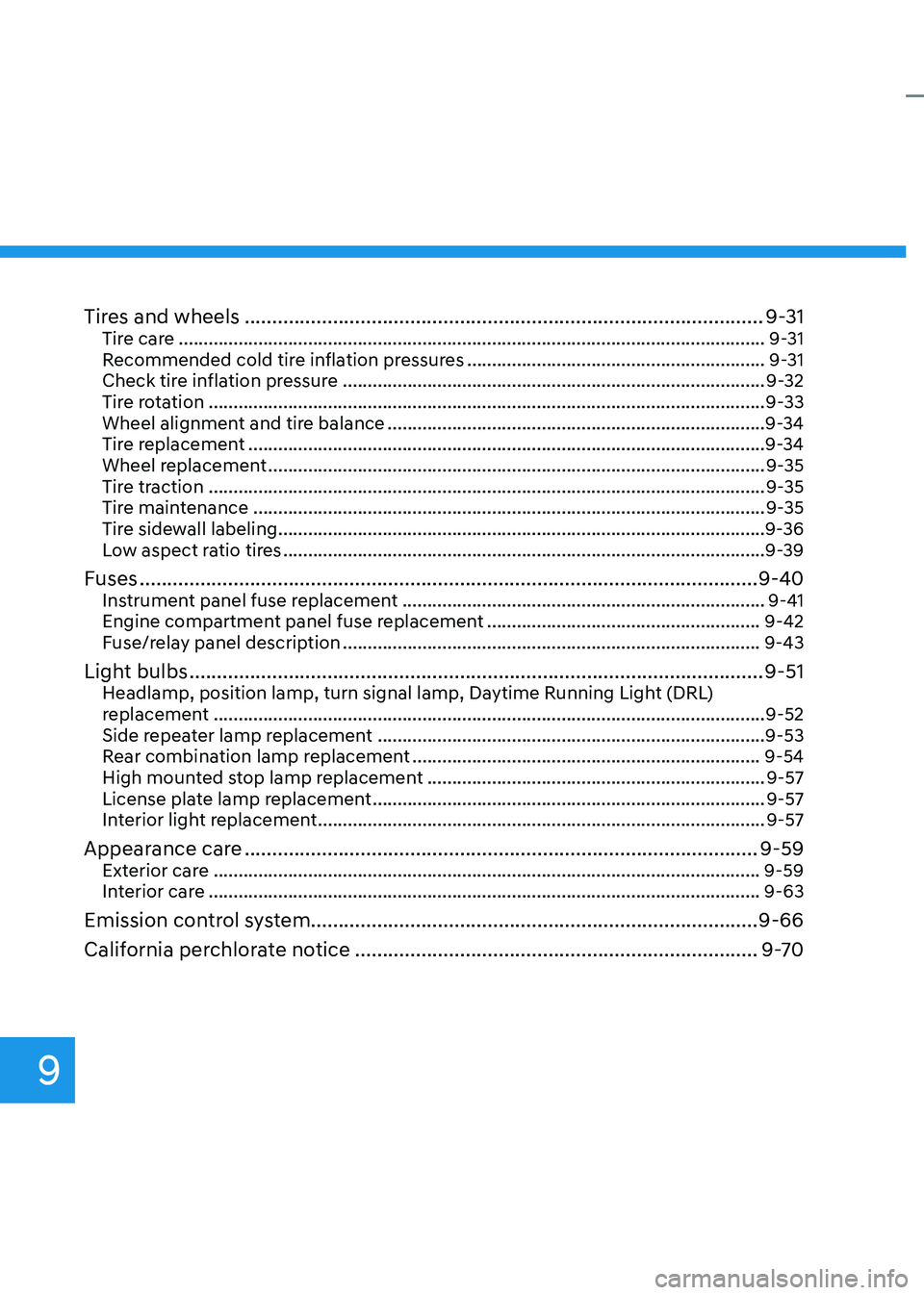
Tires and wheels ........................................................................\
......................9-31Tire care ........................................................................\
..............................................9-31
Recommended cold tire inflation pressures ............................................................9-31
Check tire inflation pressure ........................................................................\
.............9-32
Tire rotation ........................................................................\
........................................9-33
Wheel alignment and tire balance ........................................................................\
....9-34
Tire replacement ........................................................................\
................................9-34
Wheel replacement ........................................................................\
............................9-35
Tire traction ........................................................................\
........................................9-35
Tire maintenance ........................................................................\
...............................9-35
Tire sidewall labeling ........................................................................\
..........................9-36
Low aspect ratio tires ........................................................................\
.........................9-39
Fuses ........................................................................\
........................................9-40Instrument panel fuse replacement ........................................................................\
.9-41
Engine compartment panel fuse replacement .......................................................9-42
Fuse/relay panel description ........................................................................\
............9-43
Light bulbs ........................................................................\
................................9-51Headlamp, position lamp, turn signal lamp, Daytime Running Light (DRL)
replacement ........................................................................\
.......................................9-52
Side repeater lamp replacement ........................................................................\
......9-53
Rear combination lamp replacement ......................................................................9-54
High mounted stop lamp replacement ....................................................................9-57
License plate lamp replacement ........................................................................\
.......9-57
Interior light replacement ........................................................................\
..................9-57
Appearance care ........................................................................\
.....................9-59Exterior care ........................................................................\
......................................9-59
Interior care ........................................................................\
.......................................9-63
Emission control system ........................................................................\
......... 9-66
California perchlorate notice
........................................................................\
.9-70
9
Page 558 of 598
09
9-43
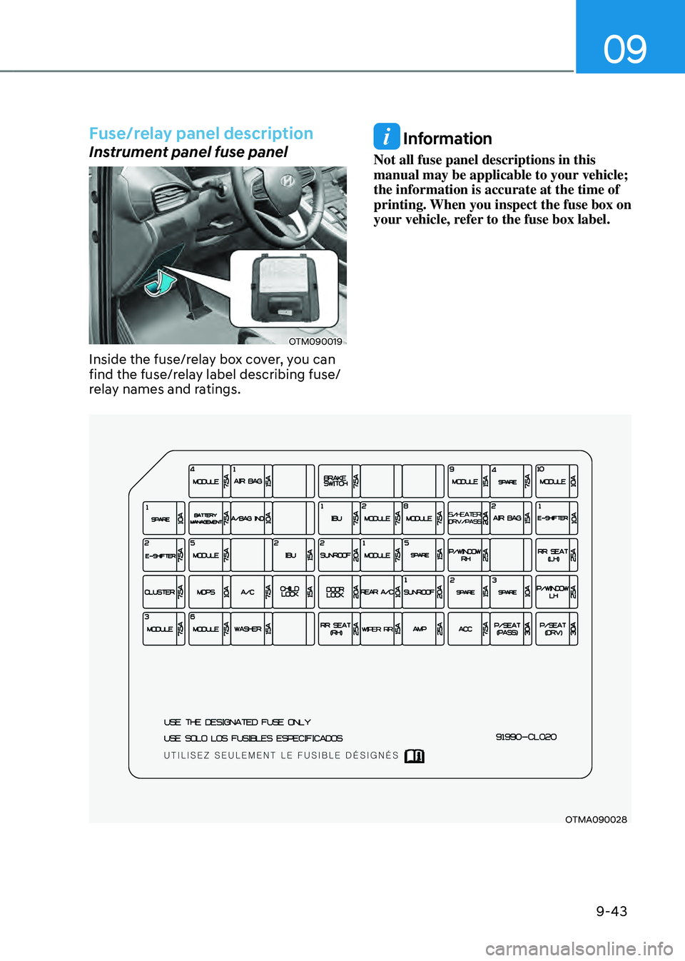
Fuse/relay panel description
Instrument panel fuse panel
OTM090019
Inside the fuse/relay box cover, you can
find the fuse/relay label describing fuse/
relay names and ratings.
Information
Not all fuse panel descriptions in this
manual may be applicable to your vehicle;
the information is accurate at the time of
printing. When you inspect the fuse box on
your vehicle, refer to the fuse box label.
OTMA090028
Page 560 of 598
09
9-45
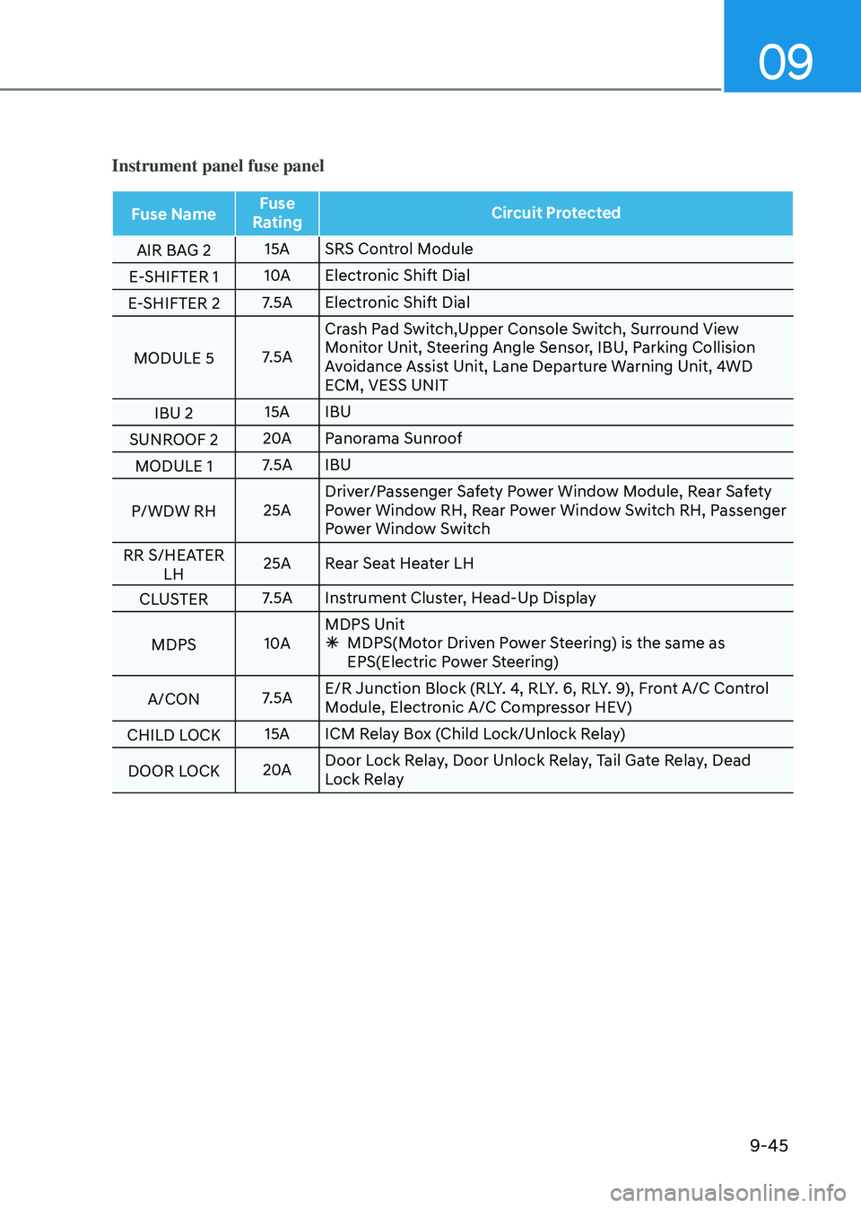
Instrument panel fuse panel
Fuse NameFuse
Rating Circuit Protected
AIR BAG 2 15A
SRS Control Module
E-SHIFTER 1 10A
Electronic Shift Dial
E-SHIFTER 2 7.5A
Electronic Shift Dial
MODULE 5 7.5ACrash Pad Switch,Upper Console Switch, Surround View
Monitor Unit, Steering Angle Sensor, IBU, Parking Collision
Avoidance Assist Unit, Lane Departure Warning Unit, 4WD
ECM, VESS UNIT
IBU 2 15A
IBU
SUNROOF 2 20A
Panorama Sunroof
MODULE 1 7.5A
IBU
P/WDW RH 25ADriver/Passenger Safety Power Window Module, Rear Safety
Power Window RH, Rear Power Window Switch RH, Passenger
Power Window Switch
RR S/HEATER LH 25A
Rear Seat Heater LH
CLUSTER 7.5A
Instrument Cluster, Head-Up Display
MDPS 10AMDPS Unit
Ã
MDPS(Motor Driven Power Steering) is the same as
EPS(Electric Power Steering)
A/CON 7.5AE/R Junction Block (RLY. 4, RLY. 6, RLY. 9), Front A/C Control
Module, Electronic A/C Compressor HEV)
CHILD LOCK 15A
ICM Relay Box (Child Lock/Unlock Relay)
DOOR LOCK 20ADoor Lock Relay, Door Unlock Relay, Tail Gate Relay, Dead
Lock Relay
Page 561 of 598
Maintenance
9-46
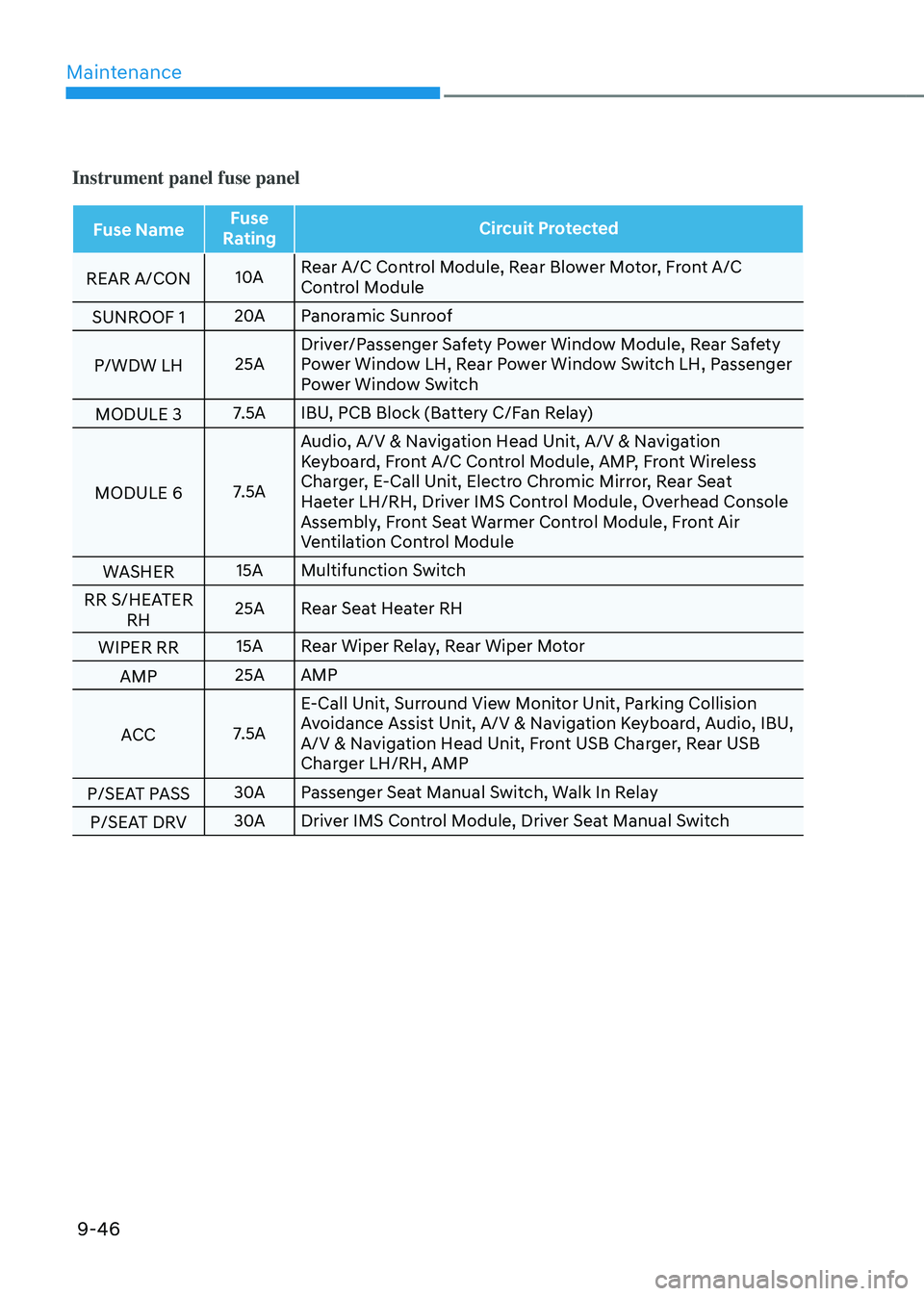
Instrument panel fuse panel
Fuse NameFuse
Rating Circuit Protected
REAR A/CON 10ARear A/C Control Module, Rear Blower Motor, Front A/C
Control Module
SUNROOF 1 20A
Panoramic Sunroof
P/WDW LH 25ADriver/Passenger Safety Power Window Module, Rear Safety
Power Window LH, Rear Power Window Switch LH, Passenger
Power Window Switch
MODULE 3 7.5A
IBU, PCB Block (Battery C/Fan Relay)
MODULE 6 7.5AAudio, A/V & Navigation Head Unit, A/V & Navigation
Keyboard, Front A/C Control Module, AMP, Front Wireless
Charger, E-Call Unit, Electro Chromic Mirror, Rear Seat
Haeter LH/RH, Driver IMS Control Module, Overhead Console
Assembly, Front Seat Warmer Control Module, Front Air
Ventilation Control Module
WASHER 15A
Multifunction Switch
RR S/HEATER RH 25A
Rear Seat Heater RH
WIPER RR 15A
Rear Wiper Relay, Rear Wiper Motor
AMP 25A
AMP
ACC 7.5AE-Call Unit, Surround View Monitor Unit, Parking Collision
Avoidance Assist Unit, A/V & Navigation Keyboard, Audio, IBU,
A/V & Navigation Head Unit, Front USB Charger, Rear USB
Charger LH/RH, AMP
P/SEAT PASS 30A
Passenger Seat Manual Switch, Walk In Relay
P/SEAT DRV 30A
Driver IMS Control Module, Driver Seat Manual Switch
Page 562 of 598
09
9-47
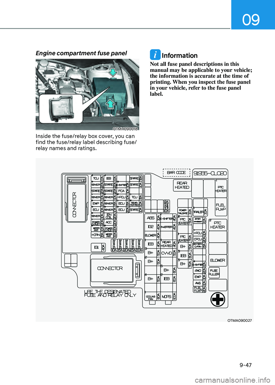
Engine compartment fuse panel
OTMH090018
Inside the fuse/relay box cover, you can
find the fuse/relay label describing fuse/
relay names and ratings.
Information
Not all fuse panel descriptions in this
manual may be applicable to your vehicle;
the information is accurate at the time of
printing. When you inspect the fuse panel
in your vehicle, refer to the fuse panel
label.
OTMA090027
Page 563 of 598
Maintenance
9-48
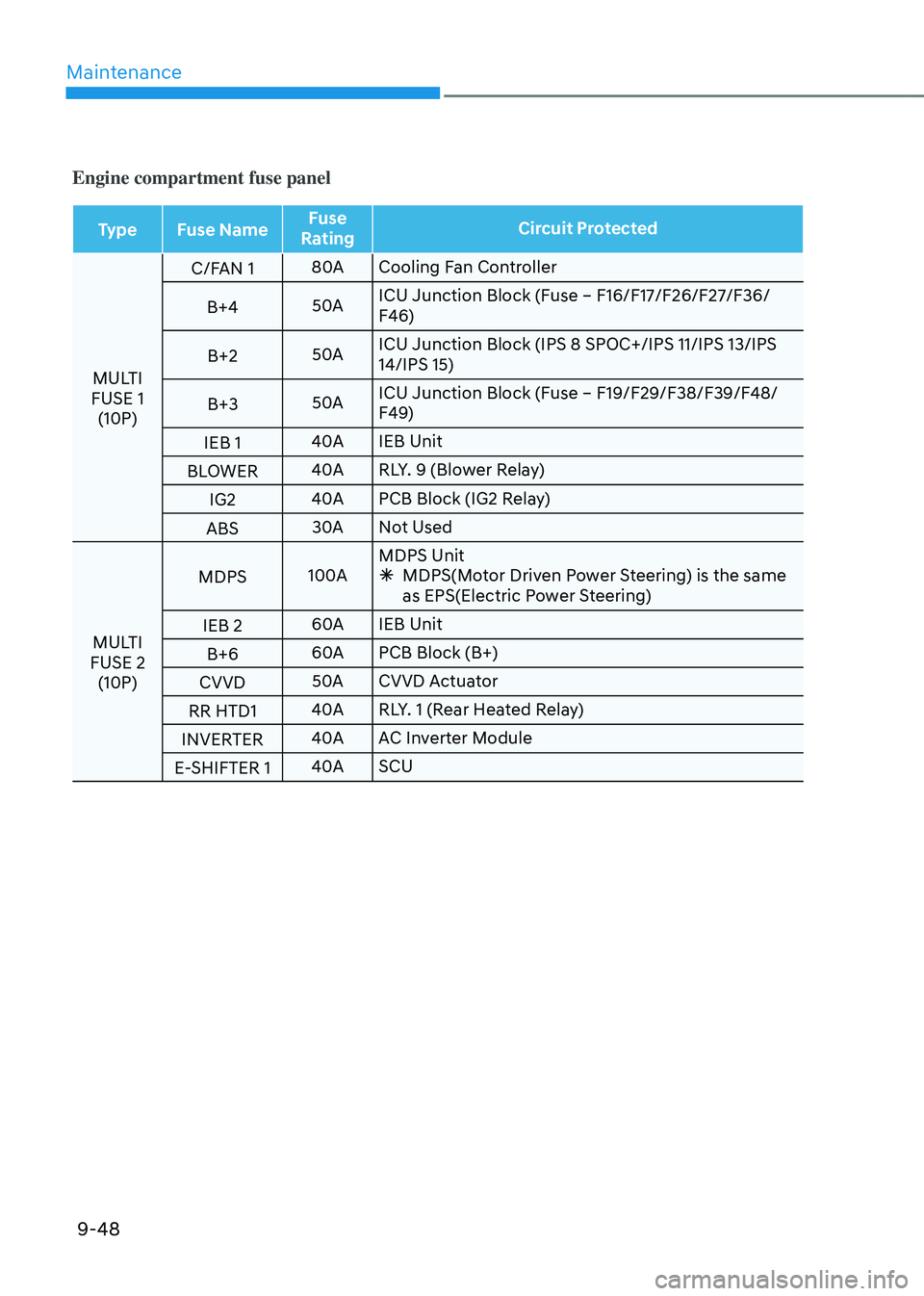
Engine compartment fuse panel
TypeFuse Name Fuse
Rating Circuit Protected
MULTI
FUSE 1 (10P) C/FAN 1
80A
Cooling Fan Controller
B+4 50AICU Junction Block (Fuse – F16/F17/F26/F27/F36/
F46)
B+2 50AICU Junction Block (IPS 8 SPOC+/IPS 11/IPS 13/IPS
14/IPS 15)
B+3 50AICU Junction Block (Fuse – F19/F29/F38/F39/F48/
F49)
IEB 1 40A
IEB Unit
BLOWER 40A
RLY. 9 (Blower Relay)
IG2 40A
PCB Block (IG2 Relay)
ABS 30A
Not Used
MULTI
FUSE 2 (10P) MDPS
100AMDPS Unit
Ã
MDPS(Motor Driven Power Steering) is the same
as EPS(Electric Power Steering)
IEB 2 60A
IEB Unit
B+6 60A
PCB Block (B+)
CVVD 50A
CVVD Actuator
RR HTD1 40A
RLY. 1 (Rear Heated Relay)
INVERTER 40A
AC Inverter Module
E-SHIFTER 1 40A
SCU
Page 564 of 598
09
9-49
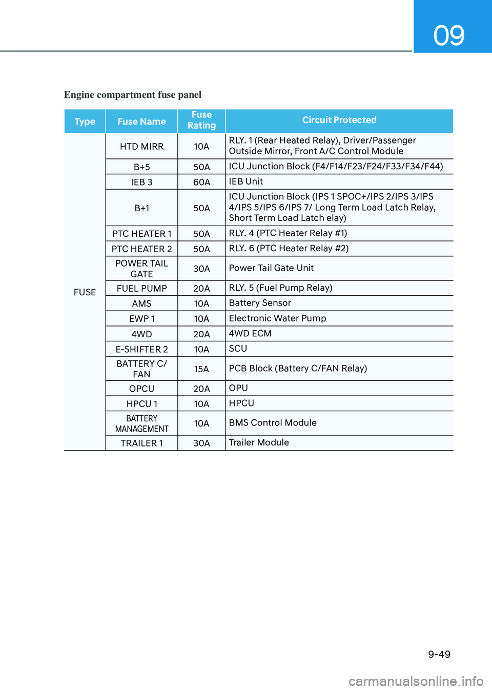
Engine compartment fuse panel
TypeFuse Name Fuse
Rating Circuit Protected
FUSE HTD MIRR
10ARLY. 1 (Rear Heated Relay), Driver/Passenger
Outside Mirror, Front A/C Control Module
B+5 50AICU Junction Block (F4/F14/F23/F24/F33/F34/F44)
IEB 3 60AIEB Unit
B+1 50AICU Junction Block (IPS 1 SPOC+/IPS 2/IPS 3/IPS
4/IPS 5/IPS 6/IPS 7/ Long Term Load Latch Relay,
Short Term Load Latch elay)
PTC HEATER 1 50ARLY. 4 (PTC Heater Relay #1)
PTC HEATER 2 50ARLY. 6 (PTC Heater Relay #2)
POWER TAIL GATE 30A
Power Tail Gate Unit
FUEL PUMP 20ARLY. 5 (Fuel Pump Relay)
AMS 10ABattery Sensor
EWP 1 10AElectronic Water Pump
4WD 20A4WD ECM
E-SHIFTER 2 10ASCU
BATTERY C/ FAN 15A
PCB Block (Battery C/FAN Relay)
OPCU 20AOPU
HPCU 1 10AHPCU
BATTERY
MANAGEMENT10A BMS Control Module
TRAILER 1 30ATrailer Module
Page 565 of 598
Maintenance
9-50
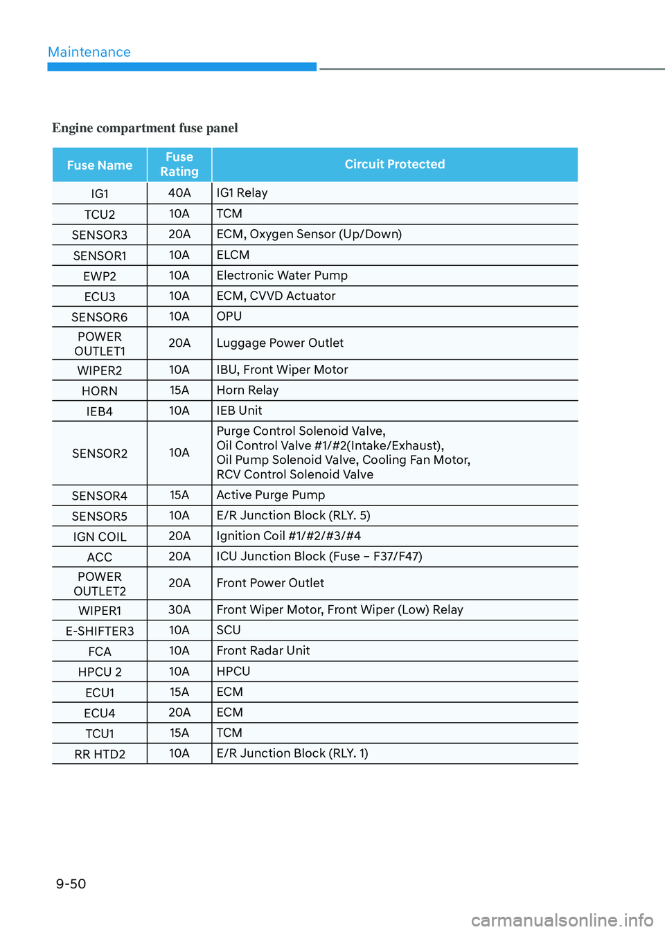
Engine compartment fuse panel
Fuse NameFuse
Rating Circuit Protected
IG1 40A
IG1 Relay
TCU2 10A
TCM
SENSOR3 20A
ECM, Oxygen Sensor (Up/Down)
SENSOR1 10A
ELCM
EWP2 10A
Electronic Water Pump
ECU3 10A
ECM, CVVD Actuator
SENSOR6 10A
OPU
POWER
OUTLET1 20A
Luggage Power Outlet
WIPER2 10A
IBU, Front Wiper Motor
HORN 15A
Horn Relay
IEB4 10A
IEB Unit
SENSOR2 10APurge Control Solenoid Valve,
Oil Control Valve #1/#2(Intake/Exhaust),
Oil Pump Solenoid Valve, Cooling Fan Motor,
RCV Control Solenoid Valve
SENSOR4 15A
Active Purge Pump
SENSOR5 10A
E/R Junction Block (RLY. 5)
IGN COIL 20A
Ignition Coil #1/#2/#3/#4
ACC 20A
ICU Junction Block (Fuse – F37/F47)
POWER
OUTLET2 20A
Front Power Outlet
WIPER1 30A
Front Wiper Motor, Front Wiper (Low) Relay
E-SHIFTER3 10A
SCU
FCA 10A
Front Radar Unit
HPCU 2 10A
HPCU
ECU1 15A
ECM
ECU4 20A
ECM
TCU1 15A
TCM
RR HTD2 10A
E/R Junction Block (RLY. 1)
Page 591 of 598
Index
I-6
Four wheel drive (4WD) ........................................................................\
.............6-37
Emergency precautions ........................................................................\
............6-42
Four Wheel Drive (4WD) operation ................................................................6-38
Reducing the risk of a rollover ........................................................................\
.6-44
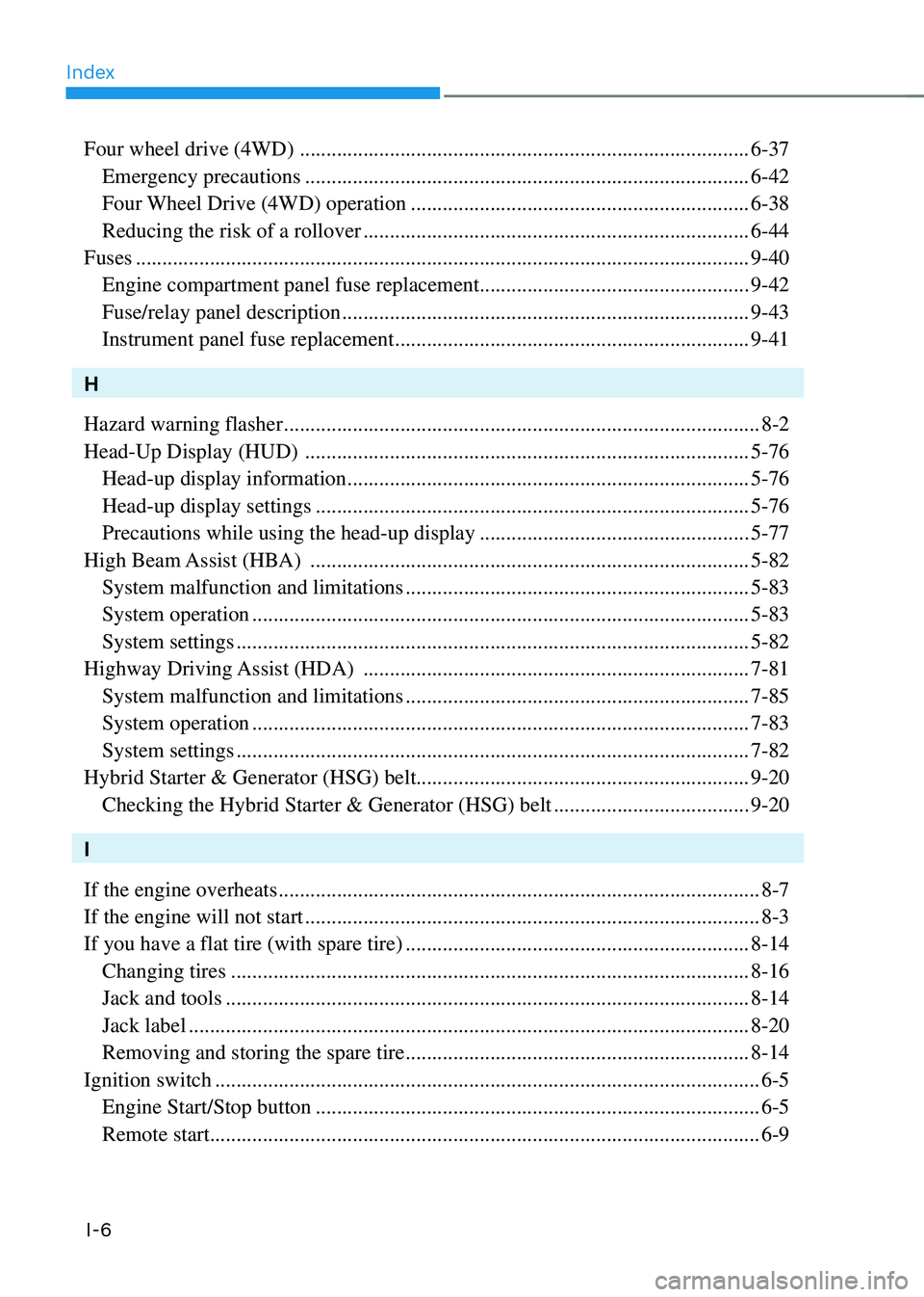
Fuses
........................................................................\
............................................9-40
Engine compartment panel fuse replacement ...................................................9-42
Fuse/relay panel description ........................................................................\
.....9-43
Instrument panel fuse replacement ...................................................................9-41
H
Hazard warning flasher
........................................................................\
..................8-2
Head-Up Display (HUD)
........................................................................\
............5-76
Head-up display information ........................................................................\
....5-76
Head-up display settings ........................................................................\
..........5-76
Precautions while using the head-up display ...................................................5-77
High Beam Assist (HBA)
........................................................................\
...........5-82
System malfunction and limitations .................................................................5-83
System operation ........................................................................\
......................5-83
System settings ........................................................................\
.........................5-82
Highway Driving Assist (HDA)
........................................................................\
.7-81
System malfunction and limitations .................................................................7-85
System operation ........................................................................\
......................7-83
System settings ........................................................................\
.........................7-82
Hybrid Starter & Generator (HSG) belt ............................................................... 9-20
Checking the Hybrid Starter & Generator (HSG) belt .....................................9-20
I
If the engine overheats
........................................................................\
...................8-7
If the engine will not start
........................................................................\
..............8-3
If you have a flat tire (with spare tire)
.................................................................8-14
Changing tires ........................................................................\
..........................8-16
Jack and tools ........................................................................\
...........................8-14
Jack label ........................................................................\
..................................8-20
Removing and storing the spare tire .................................................................8-14
Ignition switch
........................................................................\
...............................6-5
Engine Start/Stop button ........................................................................\
............6-5
Remote start ........................................................................\
................................6-9