fuel pump Hyundai Sonata
[x] Cancel search | Manufacturer: HYUNDAI, Model Year: , Model line: , Model:Pages: 286, PDF Size: 9.58 MB
Page 15 of 286

1FEATURES OF YOUR HYUNDAI2
!
B010A01NF-A
FUEL RECOMMENDATIONS
CAUTION:
Your Hyundai's New Vehicle Limited War-
ranty may not cover damage to the fuel
system and any performance problems
that are caused by the use of fuels con-
taining methanol or fuels containing
MTBE (Methyl Tertiary Butyl Ether) over
15.0% vol. (Oxygen Content 2.7% weight.)
B010B01A-AATWhat About Gasohol?Gasohol (a mixture of 90% unleaded
gasoline and 10% ethanol or grain alcohol)
may be used in your Hyundai. However, if
your engine develops driveability
problems, the use of 100% unleaded
gasoline is recommended. Fuels with
unspecified quantities of alcohol, or
alcohols other than ethanol, should not be
used.
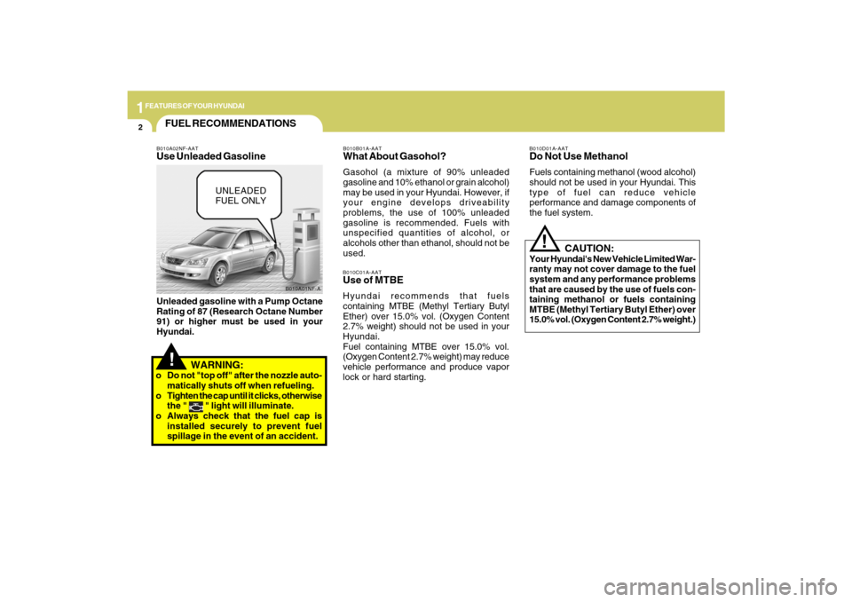
B010A02NF-AATUse Unleaded GasolineUnleaded gasoline with a Pump Octane
Rating of 87 (Research Octane Number
91) or higher must be used in your
Hyundai.
B010C01A-AATUse of MTBEHyundai recommends that fuels
containing MTBE (Methyl Tertiary Butyl
Ether) over 15.0% vol. (Oxygen Content
2.7% weight) should not be used in your
Hyundai.
Fuel containing MTBE over 15.0% vol.
(Oxygen Content 2.7% weight) may reduce
vehicle performance and produce vapor
lock or hard starting.
B010D01A-AATDo Not Use MethanolFuels containing methanol (wood alcohol)
should not be used in your Hyundai. This
type of fuel can reduce vehicle
performance and damage components of
the fuel system.
!
UNLEADED
FUEL ONLY
WARNING:
o Do not "top off" after the nozzle auto-
matically shuts off when refueling.
o Tighten the cap until it clicks, otherwise
the "
" light will illuminate.
o Always check that the fuel cap is
installed securely to prevent fuel
spillage in the event of an accident.
Page 68 of 286

1
FEATURES OF YOUR HYUNDAI
55
!
B290A03A-AATENGINE COOLANT TEMPERATURE
GAUGE
WARNING:Never remove the radiator cap when the
engine is hot. The engine coolant is under
pressure and could erupt and cause
severe burns. Wait until the engine is
cool before adding coolant to the
reservoir.The normal range is approximately in the
middle between "H" and "C". If it moves
across the dial to "H" (HOT), pull over and
stop as soon as possible and turn off the
engine. Then open the hood and, after the
engine has cooled, check the coolant level
(See "If the engine overheats" on the page
3-4.) and the water pump drive belt. If you
suspect cooling system trouble, have your
cooling system checked by a Hyundai dealer
as soon as possible.
ONF048043N
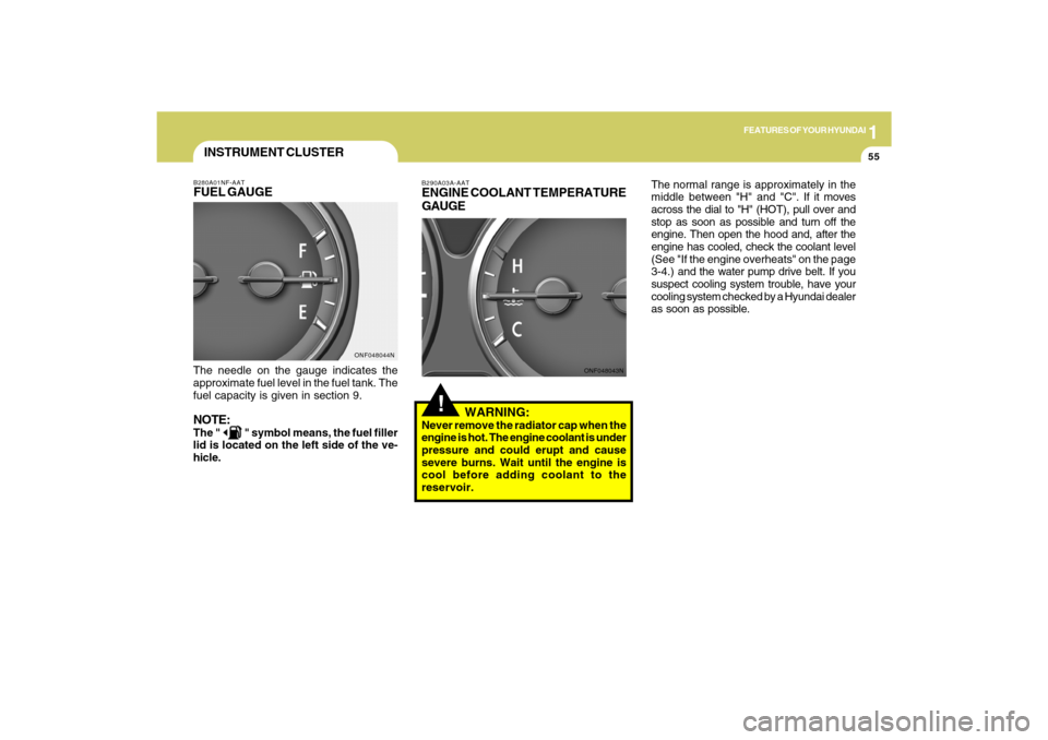
INSTRUMENT CLUSTERB280A01NF-AATFUEL GAUGEThe needle on the gauge indicates the
approximate fuel level in the fuel tank. The
fuel capacity is given in section 9.NOTE:The "
" symbol means, the fuel filler
lid is located on the left side of the ve-
hicle.
ONF048044N
Page 253 of 286

6
DO-IT-YOURSELF MAINTENANCE
38
1
2
3
4
5
6
7
8
9
10
11
12
13
14
15
16
17
18
19
20
21
22
23
24
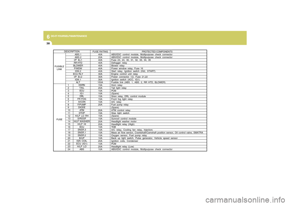
HORN
TAIL
ECU
IG1
DRL
FR FOG
A/CON
F/PUMP
DIODE
ATM
STOP
H/LP LO RH
S/ROOF
H/LP WASHER
H/LP HI
ECU
SNSR.3
SNSR.1
SNSR.2
B/UP
IGN COIL
ECU (IG1)
H/LP LO
ABS
PROTECTED COMPONENTS
ABS/ESC control module, Multipurpose check connector
ABS/ESC control module, Multipurpose check connector
Fuse 23, 24, 30, 31, 32, 33, 34, 35
Defogger relay
Blower relay
Power window relay, Fuse 16
Start relay, Ignition switch (IG2, START)
Engine control unit relay
Power connector 1/2, Fuse 21,22
Ignition switch (ACC, IG1)
Fusible Iink (ABS. 1, ABS. 2, RR HTD, BLOWER)
Horn relay
Tail light relay
PCM
(Spare)
Siren relay, DRL control module
Front fog light relay
A/C relay
Fuel pump relay
(Spare)
ATM control relay
Stop light switch
(Spare)
Sunroof control module
Headlight washer motor
Headlight relay (High)
TCM
A/C relay, Cooling fan relay, Injectors
Mass air flow sensor, Crankshaft/Camshaft position sensor, Oil control valve, SMATRA
Oxygen sensor, Fuel pump relay
Back up light switch, Pulse generator, Vehicle speed sensor
Ignition coils, Condenser
PCM
Headlight relay (Low)
ABS/ESC control module, Multipurpose check connector
ABS.1
ABS.2
I/P B+1
RR HTD
BLOWER
P/WDW
IGN.2
ECU RLY
I/P B+2
IGN.1
ALTFUSE RATING
40A
20A
40A
40A
40A
40A
40A
30A
30A
30A
150A
15A
20A
10A
10A
15A
15A
10A
20A
-
20A
15A
15A
15A
20A
20A
10A
10A
15A
15A
10A
20A
10A
20A
10A
DESCRIPTION
FUSIBLE
LINK
FUSE
Page 277 of 286

9
VEHICLE SPECIFICATIONS2
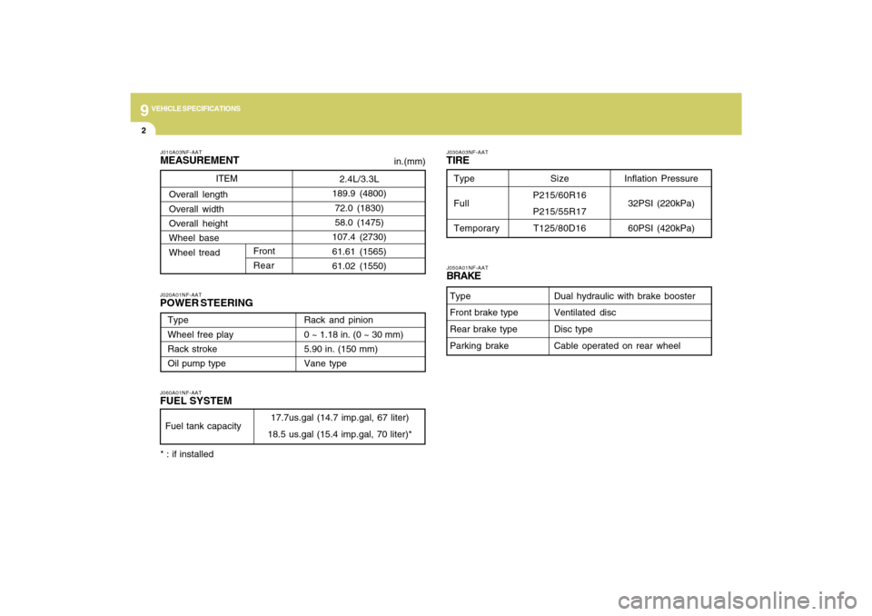
J010A03NF-AATMEASUREMENTJ060A01NF-AATFUEL SYSTEMJ020A01NF-AATPOWER STEERING
J030A03NF-AATTIRE
in.(mm)
Fuel tank capacity
17.7us.gal (14.7 imp.gal, 67 liter)
18.5 us.gal (15.4 imp.gal, 70 liter)* ITEM
J050A01NF-AATBRAKE
Dual hydraulic with brake booster
Ventilated disc
Disc type
Cable operated on rear wheel Type
Front brake type
Rear brake type
Parking brake
Type
Wheel free play
Rack stroke
Oil pump typeRack and pinion
0 ~ 1.18 in. (0 ~ 30 mm)
5.90 in. (150 mm)
Vane type
2.4L/3.3L
189.9 (4800)
72.0 (1830)
58.0 (1475)
107.4 (2730)
61.61 (1565)
61.02 (1550) Overall length
Overall width
Overall height
Wheel base
Wheel tread
Front
Rear
Inflation Pressure
32PSI (220kPa)
60PSI (420kPa)
Type
Full
TemporarySize
P215/60R16
P215/55R17
T125/80D16
* : if installed