fog light Hyundai Sonata 2004 Owner's Manual
[x] Cancel search | Manufacturer: HYUNDAI, Model Year: 2004, Model line: Sonata, Model: Hyundai Sonata 2004Pages: 208, PDF Size: 16.93 MB
Page 10 of 208
YOUR VEHICLE AT A GLANCE
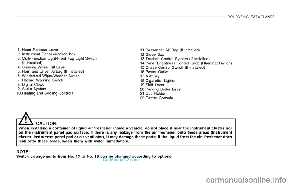
1. Hood Release Lever
2. Instrument Panel Junction box
3. Multi-Function Light/Front Fog Light Switch
(If installed)
4. Steering Wheel Tilt Lever
5. Horn and Driver Airbag (If installed)
6. Windshield Wiper/Washer Switch
7. Hazard Warning Switch
8. Digital Clock
9. Audio System
10.Heating and Cooling Controls11.Passenger Air Bag (If installed)
12.Glove Box
13.Traction Control System (If installed)
14.Panel Brightness Control Knob (Rheostat Switch)
15.Cruise Control Switch (If installed)
16.Power Outlet
17.Ashtray
18.Cigarette Lighter
19.Shift Lever
20.Parking Brake Lever
21.Cup Holder
22.Center Console
CAUTION:When installing a container of liquid air freshener inside a vehicle, do not place it near the instrument cluster nor
on the instrument panel pad surface. If there is any leakage from the air freshener onto these areas (Instrument
cluster, instrument panel pad or air ventilator), it may damage these parts. If the liquid from the air freshener does
leak onto these areas, wash them with water immediately.
!
NOTE:Switch arrangements from No. 13 to No. 15 can be changed according to options.
Page 11 of 208
YOUR VEHICLE AT A GLANCE
B255A01Y-AAT
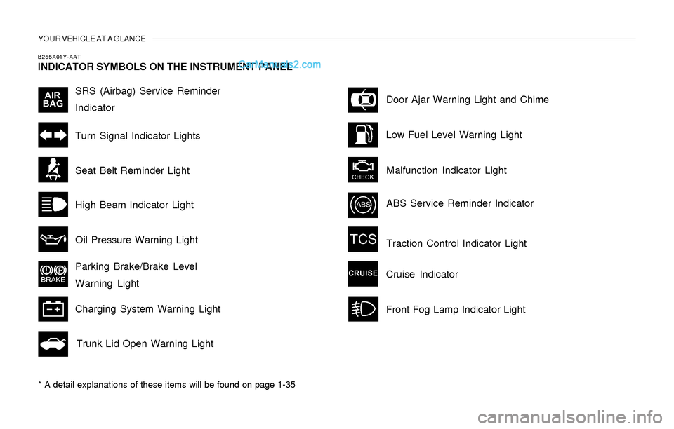
INDICATOR SYMBOLS ON THE INSTRUMENT PANEL
* A detail explanations of these items will be found on page 1-35
SRS (Airbag) Service Reminder
Indicator
Turn Signal Indicator Lights
High Beam Indicator Light
Oil Pressure Warning Light
Parking Brake/Brake Level
Warning Light
Charging System Warning Light
Trunk Lid Open Warning LightDoor Ajar Warning Light and Chime
Low Fuel Level Warning Light
Malfunction Indicator Light
Seat Belt Reminder Light
Traction Control Indicator Light
Cruise Indicator
ABS Service Reminder Indicator
Front Fog Lamp Indicator Light
Page 46 of 208
1- 34 FEATURES OF YOUR HYUNDAI
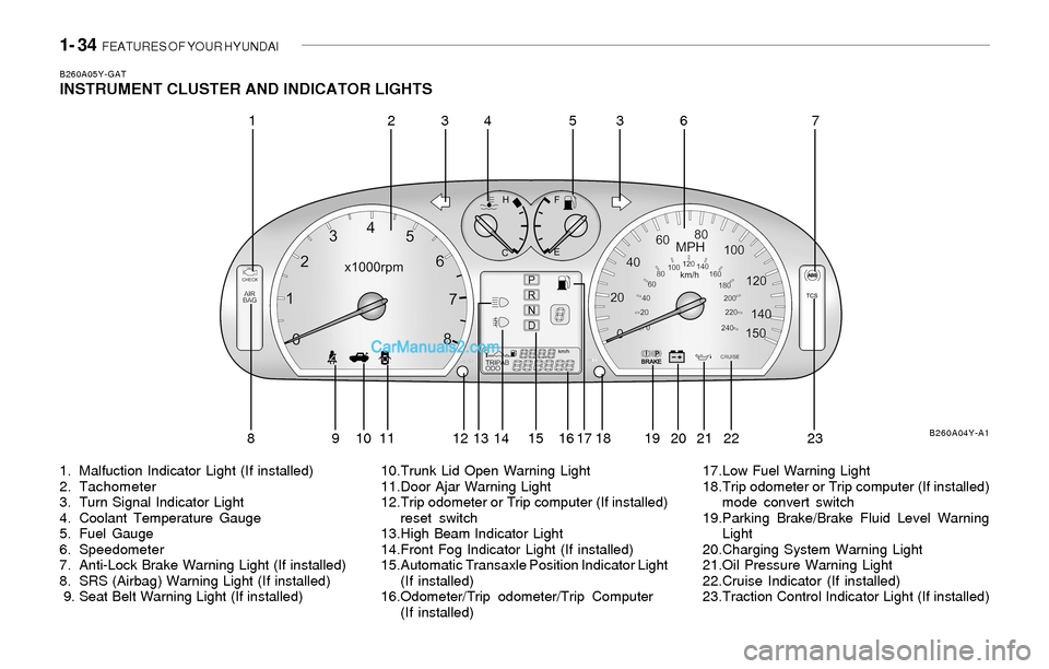
B260A05Y-GATINSTRUMENT CLUSTER AND INDICATOR LIGHTS
1. Malfuction Indicator Light (If installed)
2. Tachometer
3. Turn Signal Indicator Light
4. Coolant Temperature Gauge
5. Fuel Gauge
6. Speedometer
7. Anti-Lock Brake Warning Light (If installed)
8. SRS (Airbag) Warning Light (If installed)
9. Seat Belt Warning Light (If installed)10.Trunk Lid Open Warning Light
11.Door Ajar Warning Light
12.Trip odometer or Trip computer (If installed)
reset switch
13.High Beam Indicator Light
14.Front Fog Indicator Light (If installed)
15.Automatic Transaxle Position Indicator Light
(If installed)
16.Odometer/Trip odometer/Trip Computer
(If installed)17.Low Fuel Warning Light
18.Trip odometer or Trip computer (If installed)
mode convert switch
19.Parking Brake/Brake Fluid Level Warning
Light
20.Charging System Warning Light
21.Oil Pressure Warning Light
22.Cruise Indicator (If installed)
23.Traction Control Indicator Light (If installed)
B260A04Y-A1
12345637
8 9 10 11 12 13 14 15 16 17 18 19 20 21 22 23
Page 49 of 208
FEATURES OF YOUR HYUNDAI 1- 37
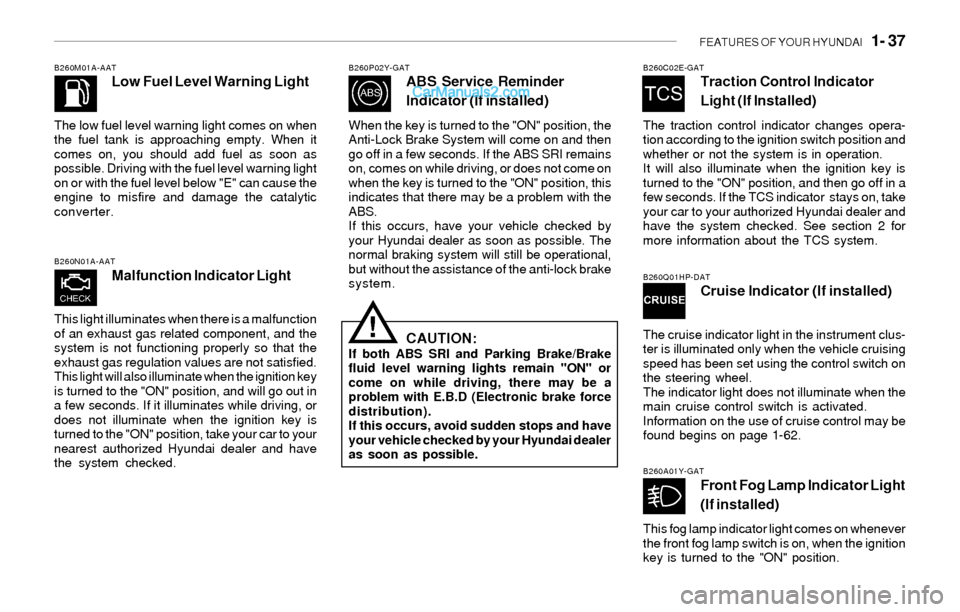
B260M01A-AATLow Fuel Level Warning Light
The low fuel level warning light comes on when
the fuel tank is approaching empty. When it
comes on, you should add fuel as soon as
possible. Driving with the fuel level warning light
on or with the fuel level below "E" can cause the
engine to misfire and damage the catalytic
converter.
B260N01A-AAT
Malfunction Indicator Light
This light illuminates when there is a malfunction
of an exhaust gas related component, and the
system is not functioning properly so that the
exhaust gas regulation values are not satisfied.
This light will also illuminate when the ignition key
is turned to the "ON" position, and will go out in
a few seconds. If it illuminates while driving, or
does not illuminate when the ignition key is
turned to the "ON" position, take your car to your
nearest authorized Hyundai dealer and have
the system checked.
B260P02Y-GATABS Service Reminder
Indicator (If installed)
When the key is turned to the "ON" position, the
Anti-Lock Brake System will come on and then
go off in a few seconds. If the ABS SRI remains
on, comes on while driving, or does not come on
when the key is turned to the "ON" position, this
indicates that there may be a problem with the
ABS.
If this occurs, have your vehicle checked by
your Hyundai dealer as soon as possible. The
normal braking system will still be operational,
but without the assistance of the anti-lock brake
system.
CAUTION:If both ABS SRI and Parking Brake/Brake
fluid level warning lights remain "ON" or
come on while driving, there may be a
problem with E.B.D (Electronic brake force
distribution).
If this occurs, avoid sudden stops and have
your vehicle checked by your Hyundai dealer
as soon as possible.
!
B260C02E-GATTraction Control Indicator
Light (If Installed)
The traction control indicator changes opera-
tion according to the ignition switch position and
whether or not the system is in operation.
It will also illuminate when the ignition key is
turned to the "ON" position, and then go off in a
few seconds. If the TCS indicator stays on, take
your car to your authorized Hyundai dealer and
have the system checked. See section 2 for
more information about the TCS system.
B260Q01HP-DATCruise Indicator (If installed)
The cruise indicator light in the instrument clus-
ter is illuminated only when the vehicle cruising
speed has been set using the control switch on
the steering wheel.
The indicator light does not illuminate when the
main cruise control switch is activated.
Information on the use of cruise control may be
found begins on page 1-62.
B260A01Y-GATFront Fog Lamp Indicator Light
(If installed)
This fog lamp indicator light comes on whenever
the front fog lamp switch is on, when the ignition
key is turned to the "ON" position.
Page 54 of 208
1- 42 FEATURES OF YOUR HYUNDAI
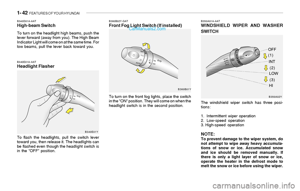
B340D01A-AATHigh-beam Switch
To turn on the headlight high beams, push the
lever forward (away from you). The High Beam
Indicator Light will come on at the same time. For
low beams, pull the lever back toward you.
B340E01A-AATHeadlight Flasher
To flash the headlights, pull the switch lever
toward you, then release it. The headlights can
be flashed even though the headlight switch is
in the "OFF" position.
B350A01A-AATWINDSHIELD WIPER AND WASHER
SWITCH
The windshield wiper switch has three posi-
tions:
1. Intermittent wiper operation
2. Low-speed operation
3. High-speed operation
NOTE:To prevent damage to the wiper system, do
not attempt to wipe away heavy accumula-
tions of snow or ice. Accumulated snow
and ice should be removed manually. If
there is only a light layer of snow or ice,
operate the heater in the defrost mode to
melt the snow or ice before using the wiper.
B360B02Y-GATFront Fog Light Switch (If installed)
To turn on the front fog lights, place the switch
in the "ON" position. They will come on when the
headlight switch is in the second position.
B340E01YB360B01Y
B350A02Y
(1)
(3)(2)
Page 82 of 208
1- 70 FEATURES OF YOUR HYUNDAI
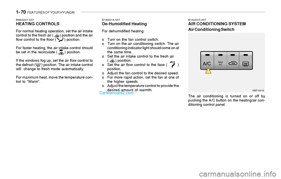
B740A01S-AATAIR CONDITIONING SYSTEM
Air Conditioning Switch
The air conditioning is turned on or off by
pushing the A/C button on the heating/air con-
ditioning control panel.
HEF-041A B690A04Y-AAT
HEATING CONTROLS
For normal heating operation, set the air intake
control to the fresh air ( ) position and the air
flow control to the floor ( ) position.
For faster heating, the air intake control should
be set in the recirculate ( ) position.
If the windows fog up, set the air flow control to
the defrost ( ) position. The air intake control
will change to fresh mode automatically.
For maximum heat, move the temperature con-
trol to "Warm".
B740C01A-AATDe-Humidified Heating
For dehumidified heating:
o Turn on the fan control switch.
o Turn on the air conditioning switch. The air
conditioning indicator light should come on at
the same time.
o Set the air intake control to the fresh air
( ) position.
o Set the air flow control to the face ( )
position.
o Adjust the fan control to the desired speed.
o For more rapid action, set the fan at one of
the higher speeds.
o Adjust the temperature control to provide the
desired amount of warmth.
Page 83 of 208
FEATURES OF YOUR HYUNDAI 1- 71
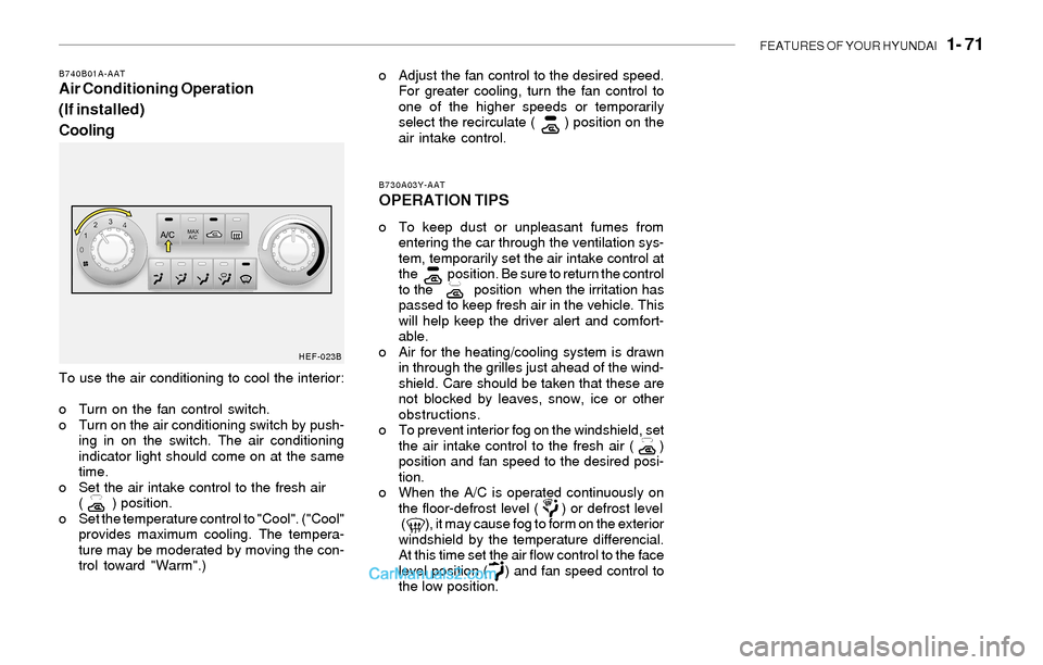
To use the air conditioning to cool the interior:
o Turn on the fan control switch.
o Turn on the air conditioning switch by push-
ing in on the switch. The air conditioning
indicator light should come on at the same
time.
o Set the air intake control to the fresh air
( ) position.
o Set the temperature control to "Cool". ("Cool"
provides maximum cooling. The tempera-
ture may be moderated by moving the con-
trol toward "Warm".)
B730A03Y-AAT
OPERATION TIPS
o To keep dust or unpleasant fumes from
entering the car through the ventilation sys-
tem, temporarily set the air intake control at
the position. Be sure to return the control
to the position when the irritation has
passed to keep fresh air in the vehicle. This
will help keep the driver alert and comfort-
able.
o Air for the heating/cooling system is drawn
in through the grilles just ahead of the wind-
shield. Care should be taken that these are
not blocked by leaves, snow, ice or other
obstructions.
o To prevent interior fog on the windshield, set
the air intake control to the fresh air ( )
position and fan speed to the desired posi-
tion.
o When the A/C is operated continuously on
the floor-defrost level ( ) or defrost level
( ), it may cause fog to form on the exterior
windshield by the temperature differencial.
At this time set the air flow control to the face
level position ( ) and fan speed control to
the low position.
B740B01A-AATAir Conditioning Operation
(If installed)
Coolingo Adjust the fan control to the desired speed.
For greater cooling, turn the fan control to
one of the higher speeds or temporarily
select the recirculate ( ) position on the
air intake control.
HEF-023B
Page 87 of 208
FEATURES OF YOUR HYUNDAI 1- 75
With the "Recirculation" mode selected, and air
from within the passenger compartment will be
drawn through the heating system and heated
or cooled according to the function selected.
NOTE:o It should be noted that prolonged opera-
tion of the heating system in "recircula-
tion" mode will give rise to fogging of the
windshield and side windows and the air
within the passenger compartment will
become stale. In addition, prolonged
use of the air conditioning with the "Re-
circulation" mode selected may result in
the air within the passenger compart-
ment becoming excessively dry.
o When the ignition switch is turned "ON"
the air intake control will change to " "
mode (regardless of the switch posi-
tion). This is normal operation. The air
intake control operates in "AUTO" mode
when turning the ignition to the ON
position if the "AUTO" mode was used
before shutting off the engine.
B980D01Y-AATHeating and Cooling System Off
Press the "OFF" button to stop the operation of
the heating and cooling system.
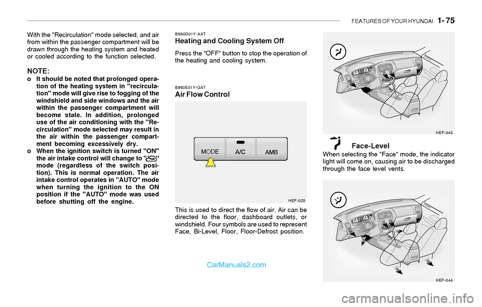
B980E01Y-GATAir Flow Control
This is used to direct the flow of air. Air can be
directed to the floor, dashboard outlets, or
windshield. Four symbols are used to represent
Face, Bi-Level, Floor, Floor-Defrost position.
Face-LevelWhen selecting the "Face" mode, the indicator
light will come on, causing air to be discharged
through the face level vents.
HEF-025HEF-043
HEF-044
Page 186 of 208
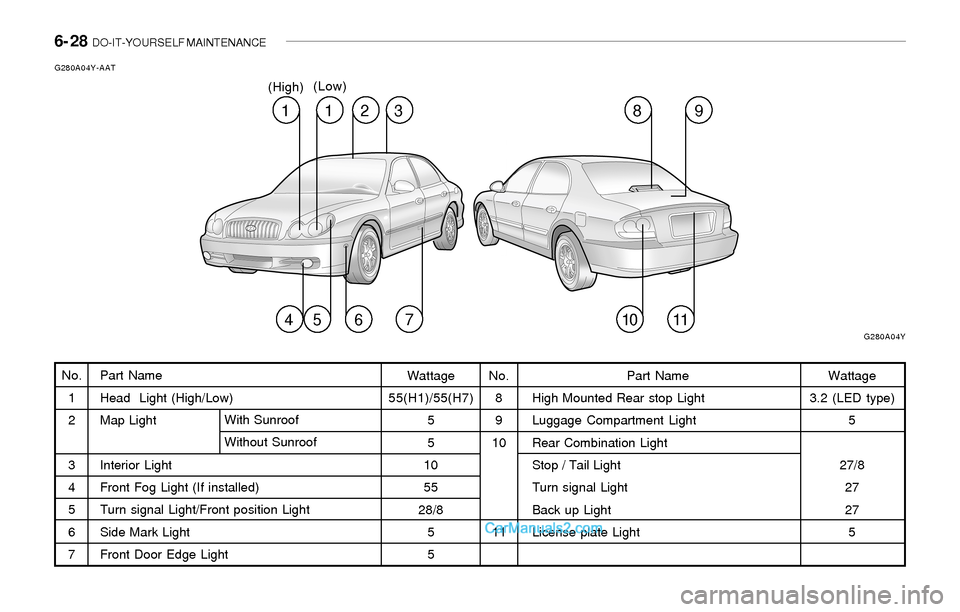
6- 28 DO-IT-YOURSELF MAINTENANCE
Part Name
Head Light (High/Low)
Map Light
Interior Light
Front Fog Light (If installed)
Turn signal Light/Front position Light
Side Mark Light
Front Door Edge LightWith Sunroof
Without Sunroof
G280A04Y-AAT
No.
1
2
3
4
5
6
7Wattage
55(H1)/55(H7)
5
5
10
55
28/8
5
5No.
8
9
10
11Wattage
3.2 (LED type)
5
27/8
27
27
5 Part Name
High Mounted Rear stop Light
Luggage Compartment Light
Rear Combination Light
Stop / Tail Light
Turn signal Light
Back up Light
License plate Light
1
G280A04Y
12389
45671011
(High)(Low)
Page 187 of 208
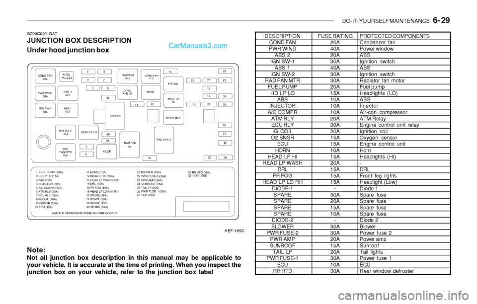
DO-IT-YOURSELF MAINTENANCE 6- 29
G200C03Y-GATJUNCTION BOX DESCRIPTION
Under hood junction box
Note:
Not all junction box description in this manual may be applicable to
your vehicle. It is accurate at the time of printing. When you inspect the
junction box on your vehicle, refer to the junction box label
DESCRIPTION
COND FAN
PWR WIND
ABS 2
IGN SW-1
ABS 1
IGN SW-2
RAD FAN MTR
FUEL PUMP
HD LP LO
ABS
INJECTOR
A/C COMPR
ATM RLY
ECU RLY
IG COIL
O2 SNSR
ECU
HORN
HEAD LP HI
HEAD LP WASH
DRL
FR FOG
HEAD LP LO RH
DIODE-1
SPARE
SPARE
SPARE
SPARE
DIODE-2
BLOWER
PWR FUSE-2
PWR AMP
SUNROOF
TAIL LP
PWR FUSE-1
ECU
RR HTDFUSE RATING
20A
40A
20A
30A
40A
30A
30A
20A
15A
10A
10A
10A
20A
30A
20A
15A
15A
10A
15A
20A
15A
15A
15A
-
30A
20A
15A
10A
-
30A
30A
20A
15A
20A
30A
10A
30APROTECTED COMPONENTS
Condenser fan
Power window
ABS
Ignition switch
ABS
Ignition switch
Radiator fan motor
Fuel pump
Headlights (LO)
ABS
Injector
Air-con compressor
ATM Relay
Engine control unit relay
Ignition coil
Oxygen sensor
Engine control unit
Horn
Headlights (HI)
-
DRL
Front fog lights
Headlight (Low)
Diode 1
Spare fuse
Spare fuse
Spare fuse
Spare fuse
Diode 2
Blower
Power fuse 2
Power amp
Sunroof
Tail lights
Power fuse 1
ECU
Rear window defroster
HEF-165C