refueling Hyundai Sonata 2018 Owner's Manual
[x] Cancel search | Manufacturer: HYUNDAI, Model Year: 2018, Model line: Sonata, Model: Hyundai Sonata 2018Pages: 522, PDF Size: 14.52 MB
Page 7 of 522

F7
Introduction
F
FU
U E
EL
L
R
R E
EQ
Q U
UI
IR
R E
EM
M E
EN
N T
TS
S
NOTICE indicates a situation
which, if not avoided, could result
in vehicle damage. Your new vehicle is designed to
obtain maximum performance with
UNLEADED FUEL, as well as mini-
mize exhaust emissions and spark
plug fouling.
Your new vehicle is designed to use
only unleaded fuel having an octane
number ((R+M)/2) of 87 (Research
Octane Number 91) or higher. (Do not
use methanol blended fuels)
To prevent damage to the engine
and engine components, never
add any fuel system cleaning
agents to the fuel tank other than
what has been specified.
Consult an authorized HYUNDAI
dealer for additional information.
Gasoline containing alcohol or
methanol
Gasohol, a mixture of gasoline and
ethanol (also known as grain alco-
hol) are being marketed along with or
instead of leaded or unleaded gaso-
line.
Do not use gasohol containing more
than 10% ethanol, and do not use
gasoline or gasohol containing any
methanol. Either of these fuels may
cause drivability problems and dam-
age to the fuel system, engine con-
trol system and emission control sys-
tem.
Discontinue using gasohol of any
kind if drivability problems occur.
NOTICE
NOTICE
CAUTION indicates a hazardous
situation which, if not avoided,
could result in minor or moder-
ate injury.
CAUTION
Do not "top off" after the noz-
zle automatically shuts off
when refueling.
Always check that the fuel cap
is installed securely to pre-
vent fuel spillage in the event
of an accident.
WARNING
Page 146 of 522
3-61
Convenient features of your vehicle
3
(Continued)
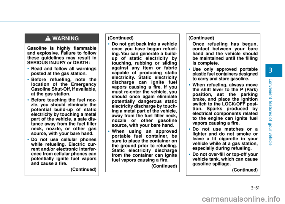
Do not get back into a vehicle
once you have begun refuel-
ing. You can generate a build-
up of static electricity by
touching, rubbing or sliding
against any item or fabric
capable of producing static
electricity. Static electricity
discharge can ignite fuel
vapors causing a fire. If you
must re-enter the vehicle, you
should once again eliminate
potentially dangerous static
electricity discharge by touch-
ing a metal part of the vehicle,
away from the fuel filler neck,
nozzle or other gasoline
source, with your bare hand.
When using an approved
portable fuel container, be
sure to place the container on
the ground prior to refueling.
Static electricity discharge
from the container can ignite
fuel vapors causing a fire.(Continued)
(Continued)Once refueling has begun,
contact between your bare
hand and the vehicle should
be maintained until the filling
is complete.
Use only approved portable
plastic fuel containers designed
to carry and store gasoline.
When refueling, always move
the shift lever to the P (Park)
position, set the parking
brake, and place the ignition
switch to the LOCK/OFF posi-
tion. Sparks produced by
electrical components related
to the engine can ignite fuel
vapors causing a fire.
Do not use matches or a
lighter and do not smoke or
leave a lit cigarette in your
vehicle while at a gas station,
especially during refueling.
Do not over-fill or top-off your
vehicle tank, which can cause
gasoline spillage. (Continued)
Gasoline is highly flammable
and explosive. Failure to follow
these guidelines may result in
SERIOUS INJURY or DEATH:
Read and follow all warnings
posted at the gas station.
Before refueling, note the
location of the Emergency
Gasoline Shut-Off, if available,
at the gas station.
Before touching the fuel noz-
zle, you should eliminate the
potential build-up of static
electricity by touching a metal
part of the vehicle, a safe dis-
tance away from the fuel filler
neck, nozzle, or other gas
source, with your bare hand.
Do not use cellular phones
while refueling. Electric cur-
rent and/or electronic interfer-
ence from cellular phones can
potentially ignite fuel vapors
and cause a fire.(Continued)
WARNING
Page 164 of 522
3-79
Convenient features of your vehicle
If the service interval is activated and
the time and distance is adjusted,
messages are displayed in the fol-
lowing situations each time the vehi-
cle is turned on.
- Service in: Displayed to inform the driver theremaining mileage and days to
service.
- Service required : Displayed when the mileage anddays to service has been reached
or passed.
Information
If any of the following conditions
occur, the mileage and number of days
to service may be incorrect.
- The battery cable is disconnected.
- The fuse switch is turned off.
- The battery is discharged. 7. Other Features
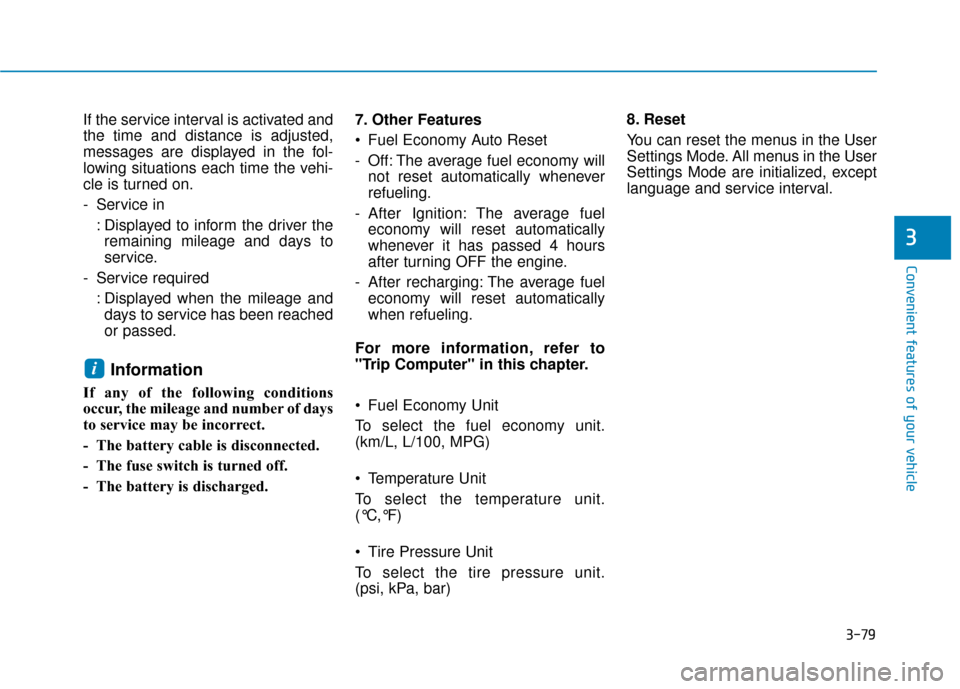
Fuel Economy Auto Reset
- Off: The average fuel economy will
not reset automatically whenever
refueling.
- After Ignition: The average fuel economy will reset automatically
whenever it has passed 4 hours
after turning OFF the engine.
- After recharging: The average fuel economy will reset automatically
when refueling.
For more information, refer to
"Trip Computer" in this chapter.
Fuel Economy Unit
To select the fuel economy unit.
(km/L, L/100, MPG)
Temperature Unit
To select the temperature unit.
(°C,°F)
Tire Pressure Unit
To select the tire pressure unit.
(psi, kPa, bar) 8. Reset
You can reset the menus in the User
Settings Mode. All menus in the User
Settings Mode are initialized, except
language and service interval.
i
3
Page 172 of 522
3-87
Convenient features of your vehicle
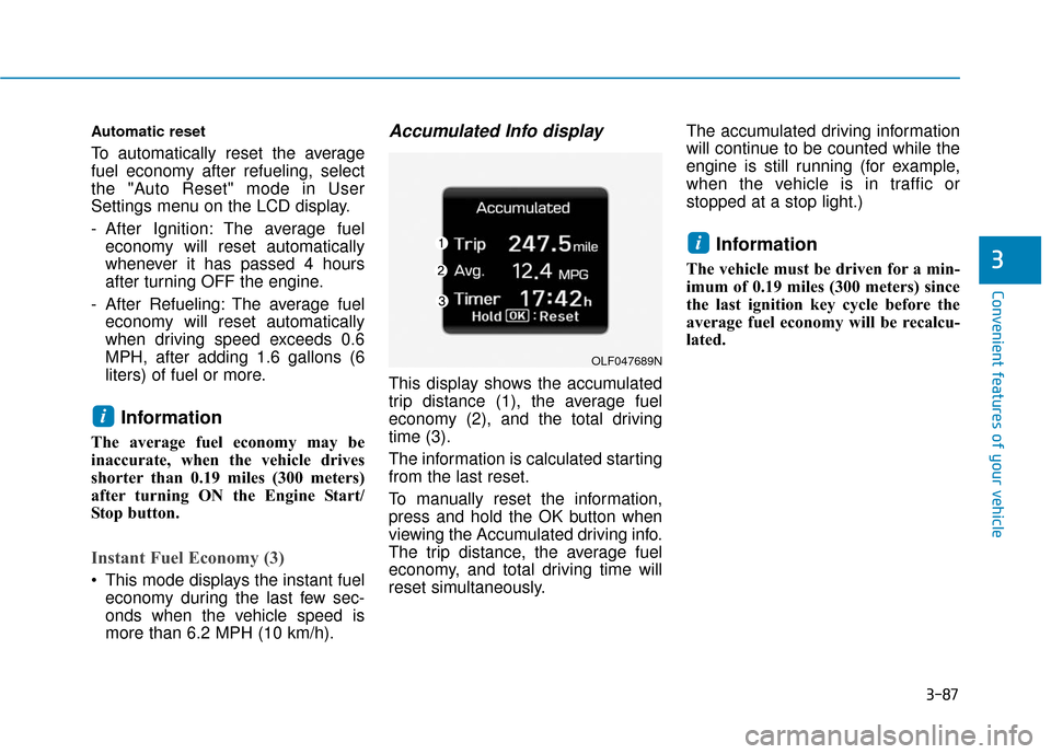
Automatic reset
To automatically reset the average
fuel economy after refueling, select
the "Auto Reset" mode in User
Settings menu on the LCD display.
- After Ignition: The average fueleconomy will reset automatically
whenever it has passed 4 hours
after turning OFF the engine.
- After Refueling: The average fuel economy will reset automatically
when driving speed exceeds 0.6
MPH, after adding 1.6 gallons (6
liters) of fuel or more.
Information
The average fuel economy may be
inaccurate, when the vehicle drives
shorter than 0.19 miles (300 meters)
after turning ON the Engine Start/
Stop button.
Instant Fuel Economy (3)
This mode displays the instant fueleconomy during the last few sec-
onds when the vehicle speed is
more than 6.2 MPH (10 km/h).
Accumulated Info display
This display shows the accumulated
trip distance (1), the average fuel
economy (2), and the total driving
time (3).
The information is calculated starting
from the last reset.
To manually reset the information,
press and hold the OK button when
viewing the Accumulated driving info.
The trip distance, the average fuel
economy, and total driving time will
reset simultaneously. The accumulated driving information
will continue to be counted while the
engine is still running (for example,
when the vehicle is in traffic or
stopped at a stop light.)
Information
The vehicle must be driven for a min-
imum of 0.19 miles (300 meters) since
the last ignition key cycle before the
average fuel economy will be recalcu-
lated.
i
i
3
OLF047689N
Page 412 of 522
7
Air Cleaner ............................................................7-31
Filter Replacement ..........................................................7-31
Climate Control Air Filter ....................................7-33
Filter Inspection ...............................................................7-33
Wiper Blades.........................................................7-35
Blade Inspection ..............................................................7-35
Blade Replacement .........................................................7-35
Battery...................................................................7-37
For Best Battery Service ..............................................7-38
Battery Recharging ........................................................7-38
Reset features .................................................................7-39
Tires and Wheels .................................................7-40
Tire Care ........................................................................\
....7-40
Recommended Cold Tire Inflation Pressures ...........7-41
Check Tire Inflation Pressure ......................................7-42
Tire Rotation...................................................................\
..7-43
Wheel Alignment and Tire Balance ............................7-44
Tire Replacement ............................................................7-44
Wheel Replacement ........................................................7-45
Tire Traction .....................................................................7-4\
5
Tire Maintenance ............................................................7-46
Tire Sidewall Labeling ....................................................7-46
Tire Terminology and Definitions................................7-50
All Season Tires ...............................................................7-53Summer Tires ...................................................................7-53
Snow Tires ........................................................................\
7-53
Radial-Ply Tires ...............................................................7-54
Low Aspect Ratio Tires..................................................7-54
Fuses ......................................................................7-\
56
Instrument Panel Fuse Replacement..........................7-57
Engine Compartment Panel Fuse Replacement.......7-58
Fuse/Relay Panel Description ......................................7-60
Light Bulbs ............................................................7-68
Headlamp, Position Lamp, Turn Signal Lamp and
Side Marker Light Bulb Replacement ........................7-69
Side Repeater Lamp Replacement ..............................7-72
Rear Combination Light Bulb Replacement ..............7-72
High Mounted Stop Lamp .............................................7-74
License Plate Light Bulb Replacement ......................7-75
Interior Light Bulb Replacement .................................7-75
Appearance Care..................................................7-77
Exterior Care ....................................................................7-77\
Interior Care .....................................................................7-8\
2
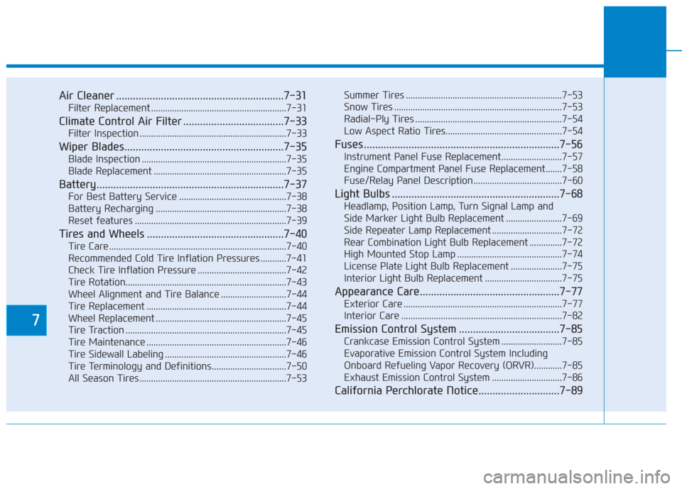
Emission Control System ....................................7-85
Crankcase Emission Control System ..........................7-85
Evaporative Emission Control System Including
Onboard Refueling Vapor Recovery (ORVR)............7-85
Exhaust Emission Control System ..............................7-86
California Perchlorate Notice.............................7-89
Page 495 of 522
7-85
7
Maintenance
E
EM
M I
IS
S S
SI
IO
O N
N
C
C O
O N
NT
TR
R O
O L
L
S
S Y
Y S
ST
T E
EM
M
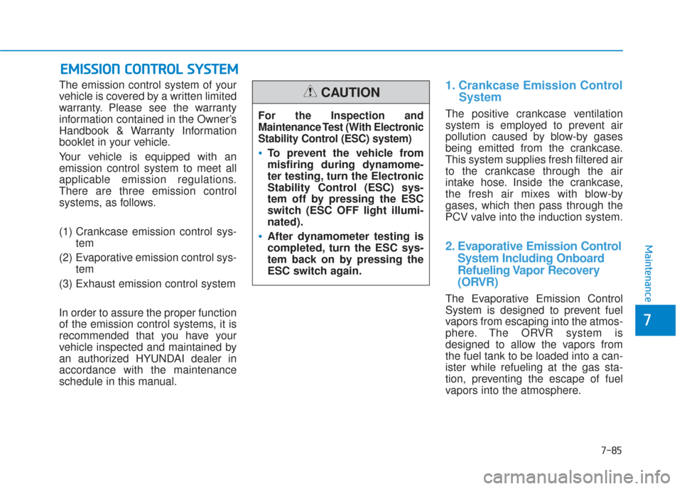
The emission control system of your
vehicle is covered by a written limited
warranty. Please see the warranty
information contained in the Owner’s
Handbook & Warranty Information
booklet in your vehicle.
Your vehicle is equipped with an
emission control system to meet all
applicable emission regulations.
There are three emission control
systems, as follows.
(1) Crankcase emission control sys-
tem
(2) Evaporative emission control sys- tem
(3) Exhaust emission control system
In order to assure the proper function
of the emission control systems, it is
recommended that you have your
vehicle inspected and maintained by
an authorized HYUNDAI dealer in
accordance with the maintenance
schedule in this manual.1. Crankcase Emission Control System
The positive crankcase ventilation
system is employed to prevent air
pollution caused by blow-by gases
being emitted from the crankcase.
This system supplies fresh filtered air
to the crankcase through the air
intake hose. Inside the crankcase,
the fresh air mixes with blow-by
gases, which then pass through the
PCV valve into the induction system.
2. Evaporative Emission ControlSystem Including Onboard
Refueling Vapor Recovery
(ORVR)
The Evaporative Emission Control
System is designed to prevent fuel
vapors from escaping into the atmos-
phere. The ORVR system is
designed to allow the vapors from
the fuel tank to be loaded into a can-
ister while refueling at the gas sta-
tion, preventing the escape of fuel
vapors into the atmosphere.
For the Inspection and
Maintenance Test (With Electronic
Stability Control (ESC) system)
To prevent the vehicle from
misfiring during dynamome-
ter testing, turn the Electronic
Stability Control (ESC) sys-
tem off by pressing the ESC
switch (ESC OFF light illumi-
nated).
After dynamometer testing is
completed, turn the ESC sys-
tem back on by pressing the
ESC switch again.
CAUTION
Page 516 of 522
I-4
Emission Control System ...............................................7-85Crankcase Emission Control System .........................7-85
\Evaporative Emission Control System Including
Onboard Refueling Vapor Recovery (ORVR) .............7-85
Exhaust Emission Control System .............................7-86
Engine ........................................................................\
.......8-2
Engine compartment..................................................1-6, 7-3
Engine Coolant ...............................................................7-26 Changing Engine Coolant ..........................................7-28
Checking the Engine Coolant Level ..........................7-26
Engine Number ...............................................................8-11
Engine Oil .......................................................................7\
-23 Checking the Engine Oil and Filter ...........................7-25
Checking the Engine Oil Level ..................................7-23
Explanation of Scheduled Maintenance Items ...............7-20 Air Cleaner Filter .......................................................7-20
Air Conditioning Refrigerant .....................................7-22
Automatic Transmission Fluid ...................................7-21
Brake Discs, Pads, Calipers and Rotors .....................7-22
Brake Fluid .................................................................7-22
Brake hoses and Lines................................................7-22
Cooling System ..........................................................7-21
Drive Belts..................................................................7-20
Drive Shafts and Boots ..............................................7-22
Ecoshift Dual Clutch Transmission Fluid ..................7-21 Engine Coolant ...........................................................7-21
Engine Oil and Filter ..................................................7-20
Exhaust Pipe and Muffler...........................................7-22
Fuel Filter ...................................................................7-20
Fuel Lines, Fuel Hoses and Connections ...................7-20
Parking Brake .............................................................7-22
Spark Plugs.................................................................7-20
Steering Gear Box, Linkage & Boots/ Lower Arm Ball Joint .............................................7-22
Suspension Mounting Bolts .......................................7-22
Valve Clearance ..........................................................7-21
Vapor Hose and Fuel Filler Cap .................................7-20
Exterior features..............................................................3-52 Fuel Filler Door ..........................................................3-59
Hood ........................................................................\
...3-52
Smart Trunk ................................................................3-56
Trunk ........................................................................\
..3-53
Exterior overview (I) ........................................................1-2
Exterior overview (II) .......................................................1-3
Fuses ........................................................................\
.......7-56 Engine Compartment Panel Fuse Replacement .........7-58
Fuse/Relay Panel Description ....................................7-60
Instrument Panel Fuse Replacement ..........................7-57
Index
E
F