sensor Hyundai Sonata 2020 Service Manual
[x] Cancel search | Manufacturer: HYUNDAI, Model Year: 2020, Model line: Sonata, Model: Hyundai Sonata 2020Pages: 537, PDF Size: 14.54 MB
Page 259 of 537
05
5-129
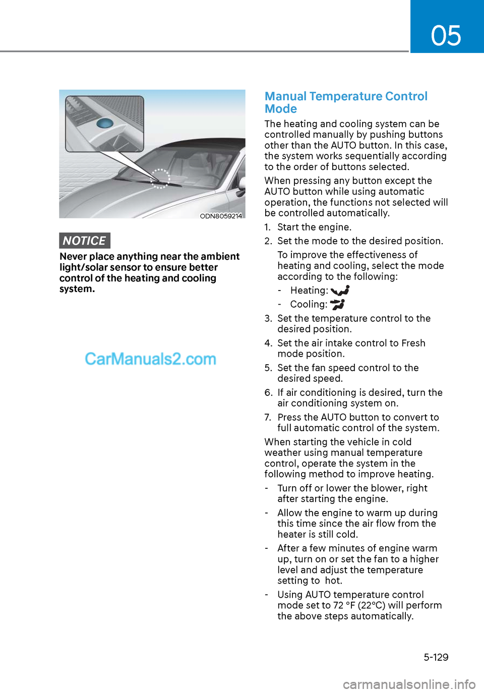
ODN8059214ODN8059214
NOTICE
Never place anything near the ambient
light/solar sensor to ensure better
control of the heating and cooling
system.
Manual Temperature Control
Mode
The heating and cooling system can be
controlled manually by pushing buttons
other than the AUTO button. In this case,
the system works sequentially according
to the order of buttons selected.
When pressing any button except the
AUTO button while using automatic
operation, the functions not selected will
be controlled automatically.
1. Start the engine.
2. Set the mode to the desired position.To improve the effectiveness of
heating and cooling, select the mode
according to the following: - Heating:
- Cooling:
3. Set the temperature control to the desired position.
4. Set the air intake control to Fresh mode position.
5. Set the fan speed control to the desired speed.
6. If air conditioning is desired, turn the air conditioning system on.
7. Press the AUTO button to convert to full automatic control of the system.
When starting the vehicle in cold
weather using manual temperature
control, operate the system in the
following method to improve heating.
- Turn off or lower the blower, right
after starting the engine.
- Allow the engine to warm up during this time since the air flow from the
heater is still cold.
- After a few minutes of engine warm up, turn on or set the fan to a higher
level and adjust the temperature
setting to hot.
- Using AUTO temperature control
mode set to 72 °F (22°C) will perform
the above steps automatically.
Page 271 of 537
05
5-141
Auto Defogging System (Only
for Automatic Climate Control
System, if equipped)
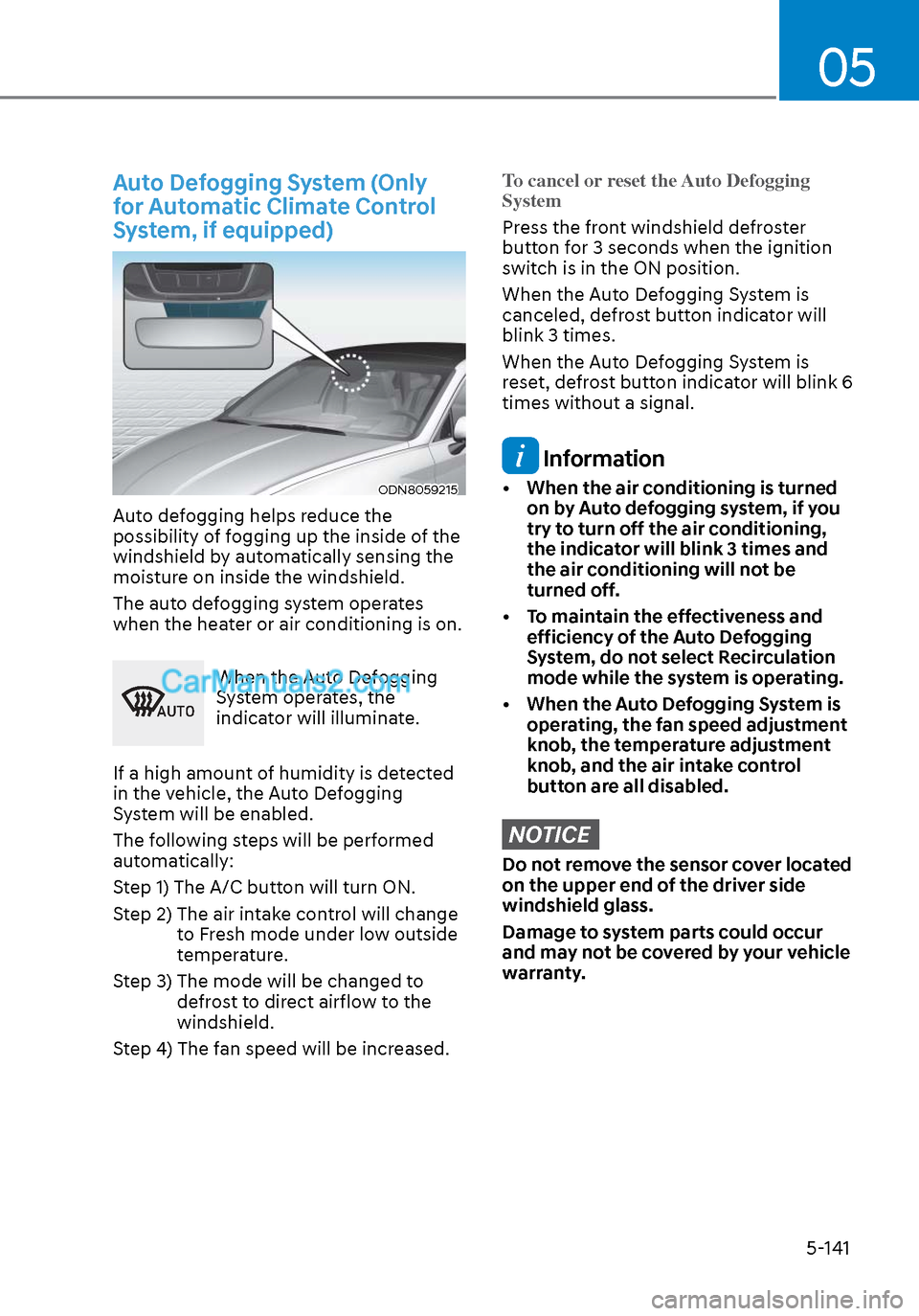
ODN8059215ODN8059215
Auto defogging helps reduce the
possibility of fogging up the inside of the
windshield by automatically sensing the
moisture on inside the windshield.
The auto defogging system operates
when the heater or air conditioning is on.
�$�8�7�2
When the Auto Defogging
System operates, the
indicator will illuminate.
If a high amount of humidity is detected
in the vehicle, the Auto Defogging
System will be enabled.
The following steps will be performed
automatically:
Step 1) The A/C button will turn ON.
Step 2) The air intake control will change to Fresh mode under low outside
temperature.
Step 3) The mode will be changed to defrost to direct airflow to the
windshield.
Step 4) The fan speed will be increased.
To cancel or reset the Auto Defogging
System
Press the front windshield defroster
butt
on for 3 seconds when the ignition
switch is in the ON position.
When the Auto Defogging System is
canceled, defrost button indicator will
blink 3 times.
When the Auto Defogging System is
reset, defrost button indicator will blink 6
times without a signal.
Information
• When the air conditioning is turned on by Auto defogging system, if you
try to turn off the air conditioning,
the indicator will blink 3 times and
the air conditioning will not be
turned off.
• To maintain the effectiveness and efficiency of the Auto Defogging
System, do not select Recirculation
mode while the system is operating.
• When the Auto Defogging System is operating, the fan speed adjustment
knob, the temperature adjustment
knob, and the air intake control
button are all disabled.
NOTICE
Do not remove the sensor cover located
on the upper end of the driver side
windshield glass.
Damage to system parts could occur
and may not be covered by your vehicle
warranty.
Page 285 of 537
6
6. While Driving
Before Driving ........................................................................\
........................ 6-5Before Entering the Vehicle ........................................................................\
............. 6-5
Before Starting ........................................................................\
................................. 6-5
Ignition Switch ........................................................................\
.......................6-6Key Ignition Switch ........................................................................\
........................... 6-6
Engine Start/Stop Button ........................................................................\
................ 6-9
Remote Start ........................................................................\
.................................... 6-12
Automatic Transmission ........................................................................\
.......6-13Automatic Transmission Operation ........................................................................\
6-13
Parking .................................................................\
....................................................6-16
LCD Display Message ........................................................................\
...................... 6-17
Good Driving Practices ........................................................................\
..................6-18
Paddle Shifter (Manual Shift Mode) ......................................................................6-\
19
Brake System ........................................................................\
........................ 6-20Power Brakes ........................................................................\
.................................. 6-20
Disc Brakes Wear Indicator......................................................................\
.............. 6-20
Electronic Parking Brake (EPB) ........................................................................\
....... 6-21
Auto Hold ........................................................................\
........................................ 6-24
Anti-lock Brake System (ABS) ..................................................................... 6-27Electronic Stability Control (ESC) ........................................................................\
. 6-29
Vehicle Stability Management (VSM) ....................................................................6-31
Hill-Start Assist Control (HAC) ........................................................................\
....... 6-32
Good Braking Practices ................................................................\
......................... 6-32
ISG (Idle Stop and Go) system..................................................................... 6-33To Activate the ISG System ........................................................................\
............ 6-33
To Deactivate the ISG System ........................................................................\
....... 6-35
ISG System Malfunction ........................................................................\
................ 6-35
Battery Sensor Deactivation ........................................................................\
.......... 6-36
Drive Mode Integrated Control System ...................................................... 6-37Drive Mode ........................................................................\
..................................... 6-37
Page 286 of 537
Forward Collision – Avoidance Assist (FCA) - Sensor Fusion .................. 6-40System Setting and Activation ........................................................................\
..... 6-40
FCA Warning Message and Brake Control ............................................................ 6-42
FCA Sensor ........................................................................\
..................................... 6-45
System Malfunction ........................................................................\
....................... 6-47
Limitations of the System ........................................................................\
..............6-48
Forward Collision-Avoidance Assist - Junction Turning ...................................... 6-55
Lane Keeping Assist (LKA) ........................................................................\
...6-59LKA Operation ........................................................................\
................................ 6-61
LKA System Function Change ........................................................................\
....... 6-61
Warning Light and Message ........................................................................\
..........6-64
Limitations of the System ........................................................................\
.............. 6-65
Blind-Spot Collision Warning (BCW) /
Blind-Spot Collision-Avoidance Assist (BCA) ............................................. 6-67
System Description ........................................................................\
........................ 6-67
System Setting and Activation ........................................................................\
......6-68
Warning and System Control ........................................................................\
......... 6-70
Detecting Sensors (Front view camera and Rear corner radar) .......................... 6-72
Limitations of the System ........................................................................\
.............. 6-75
Driver Attention Warning (DAW) ................................................................ 6-79System Setting and Operation ........................................................................\
...... 6-79
Resetting the System ........................................................................\
..................... 6-81
System Standby ........................................................................\
.............................. 6-82
System Malfunction ........................................................................\
....................... 6-82
Leading Vehicle Departure Alert ........................................................................\
...6-84
Blind-Spot View Monitor (BVM) .................................................................. 6-87
Smart cruise control (SCC) ........................................................................\
6-88
Smart Cruise Control Switch ........................................................................\
.........6-89
To Convert to Cruise Control Mode ......................................................................6-\
89
Smart Cruise Control Speed ........................................................................\
......... 6-90
Smart Cruise Control Vehicle-to-Vehicle Distance ..............................................6-96
Limitations of the System ........................................................................\
............. 6-101
6
Page 287 of 537
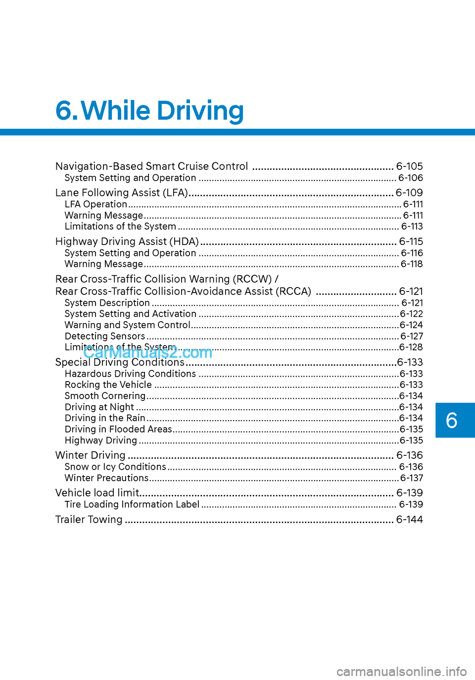
Navigation-Based Smart Cruise Control ................................................. 6-105System Setting and Operation ........................................................................\
.... 6-106
Lane Following Assist (LFA) ....................................................................... 6-109LFA Operation ........................................................................\
................................. 6-111
Warning Message ........................................................................\
........................... 6-111
Limitations of the System ........................................................................\
............. 6-113
Highway Driving Assist (HDA) .................................................................... 6-115System Setting and Operation ........................................................................\
..... 6-116
Warning Message ........................................................................\
.......................... 6-118
Rear Cross-Traffic Collision Warning (RCCW) /
Rear Cross-Traffic Collision-Avoidance Assist (RCCA) ............................ 6-121
System Description ........................................................................\
....................... 6-121
System Setting and Activation ........................................................................\
..... 6-122
Warning and System Control ........................................................................\
........6-124
Detecting Sensors ........................................................................\
......................... 6-127
Limitations of the System ........................................................................\
.............6-128
Special Driving Conditions ........................................................................\
.6-133Hazardous Driving Conditions ................................................\
.............................6-133
Rocking the Vehicle .................................................................\
.............................6-133
Smooth Cornering ........................................................................\
.........................6-134
Driving at Night ........................................................................\
.............................6-134
Driving in the Rain ........................................................................\
.........................6-134
Driving in Flooded Areas ........................................................................\
...............6-135
Highway Driving ........................................................................\
............................6-135
Winter Driving ........................................................................\
.................... 6-136Snow or Icy Conditions ........................................................................\
................ 6-136
Winter Precautions ........................................................................\
........................ 6-137
Vehicle load limit.......................................................\
................................. 6-139Tire Loading Information Label ........................................................................\
... 6-139
Trailer Towing ........................................................................\
..................... 6-144
6
6. While Driving
Page 317 of 537
06
6-33
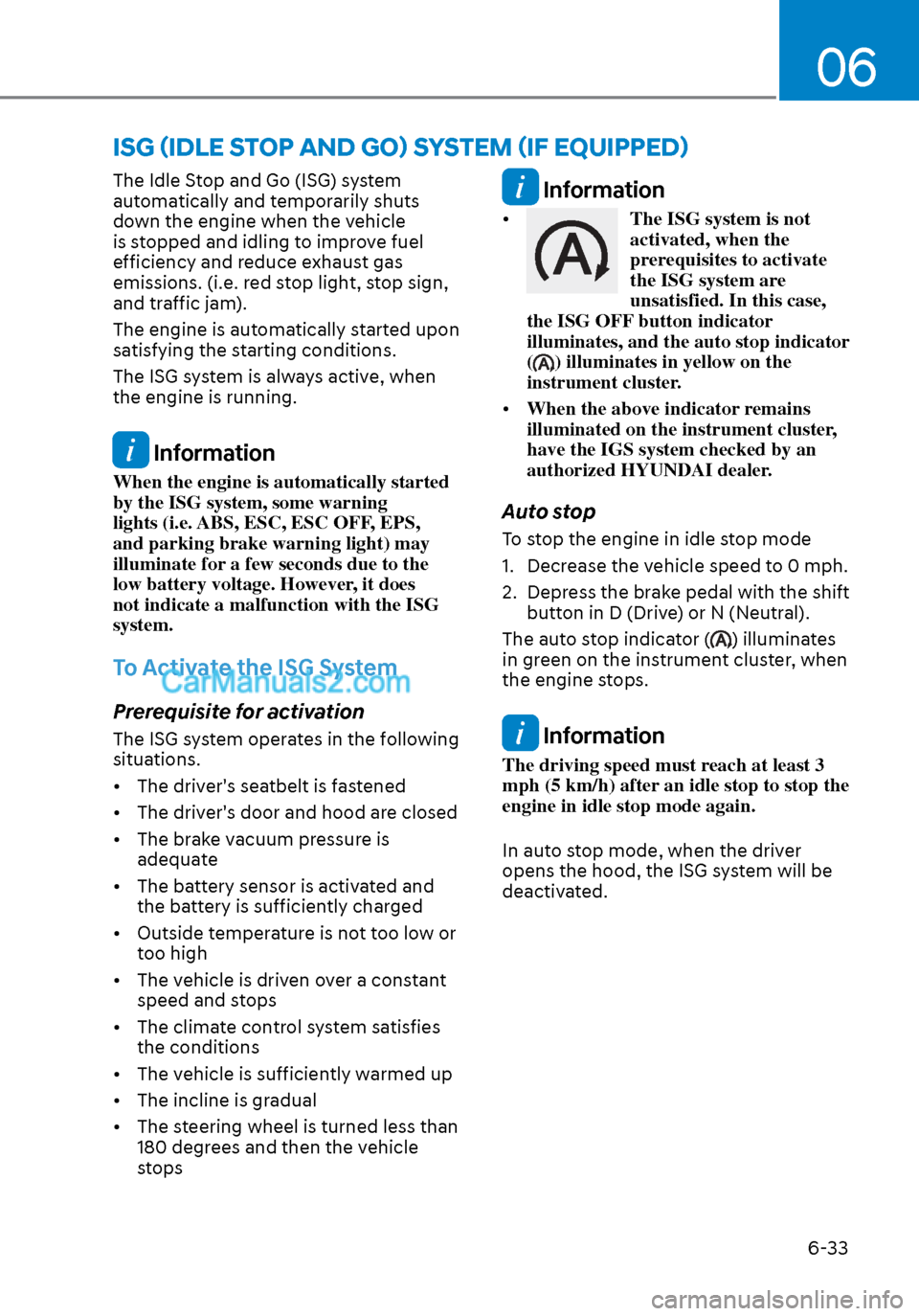
The Idle Stop and Go (ISG) system
automatically and temporarily shuts
down the engine when the vehicle
is stopped and idling to improve fuel
efficiency and reduce exhaust gas
emissions. (i.e. red stop light, stop sign,
and traffic jam).
The engine is automatically started upon
satisfying the starting conditions.
The ISG system is always active, when
the engine is running.
Information
When the engine is automatically started
by the ISG system, some warning
lights (i.e. ABS, ESC, ESC OFF, EPS,
and parking brake warning light) may
illuminate for a few seconds due to the
low battery voltage. However, it does
not indicate a malfunction with the ISG
system.
To Activate the ISG System
Prerequisite for activation
The ISG system operates in the following
situations.
• The driver's seatbelt is fastened
• The driver's door and hood are closed
• The brake vacuum pressure is adequate
• The battery sensor is activated and the battery is sufficiently charged
• Outside temperature is not too low or too high
• The vehicle is driven over a constant speed and stops
• The climate control system satisfies the conditions
• The vehicle is sufficiently warmed up
• The incline is gradual
• The steering wheel is turned less than 180 degrees and then the vehicle
stops
Information
• The ISG system is not
activated, when the
prerequisites to activate
the ISG system are
unsatisfied. In this case,
the ISG OFF button indicator
illuminates, and the auto stop indicator
(
) illuminates in yellow on the
instrument cluster.
• When the above indicator remains
illuminated on the instrument cluster,
have the IGS system checked by an
authorized HYUNDAI dealer.
Auto stop
To stop the engine in idle stop mode
1. Decrease the vehicle speed to 0 mph.
2. Depress the brake pedal with the shift
button in D (Drive) or N (Neutral).
The auto stop indicator (
) illuminates
in green on the instrument cluster, when
the engine stops.
Information
The driving speed must reach at least 3
mph (5 km/h) after an idle stop to stop the
engine in idle stop mode again.
In auto stop mode, when the driver
opens the hood, the ISG system will be
deactivated.
ISG (IDLE STOP AND GO) SYSTEM (IF EQUIPPED)
Page 319 of 537

06
6-35
OIK057086NOIK057086N
The auto start is temporarily deactivated
in the following situations.
When the gear is shifted from N (Neutral)
t
o R (Reverse), D (Drive) or Manual
shift mode without the brake pedal
depressed. A message "Press brake pedal
for Auto Start" will appear on the LCD
display. To activate auto start, depress
the brake pedal.
To Deactivate the ISG System
• Press the ISG OFF button to deactivate the ISG system. Then, the
ISG OFF button indicator illuminates.
• Press the ISG OFF button again to reactivate the ISG system. Then, the
ISG OFF button indicator turns OFF.
ISG System Malfunction
The ISG system may not operate:
When there is a malfunction with the ISG
sensor
s or the ISG system.
The followings occur, when there is a
malfunction with the ISG system:
• The auto stop indicator (
) will blink
in yellow on the instrument cluster.
• The light on the ISG OFF button will illuminate.
Information
• When you cannot turn OFF the ISG
OFF button indicator by pressing
the ISG OFF button, or when the
malfunction with the ISG system
persists, contact an authorized
HYUNDAI dealer.
• You can turn off the ISG OFF button
indicator by driving over 50 mph (80
km/h) for up to 2 hours with the fan
speed below the 2nd position. If the
ISG OFF button indicator remains
ON, contact an authorized HYUNDAI
dealer.
WARNING
When the engine is in auto stop mode,
the engine may restart. Before leaving
the vehicle or checking the engine
compartment, stop the engine placing
the ignition switch to the LOCK/OFF
position or remove the ignition key.
Page 320 of 537
![Hyundai Sonata 2020 Service Manual While Driving6-36
Battery Sensor Deactivation
ODN8A069204ODN8A069204
[A] : Battery sensor
The battery sensor is deactivated, when
the battery is disconnected from the
negative pole for maintenance p Hyundai Sonata 2020 Service Manual While Driving6-36
Battery Sensor Deactivation
ODN8A069204ODN8A069204
[A] : Battery sensor
The battery sensor is deactivated, when
the battery is disconnected from the
negative pole for maintenance p](/img/35/16773/w960_16773-319.png)
While Driving6-36
Battery Sensor Deactivation
ODN8A069204ODN8A069204
[A] : Battery sensor
The battery sensor is deactivated, when
the battery is disconnected from the
negative pole for maintenance purpose.
In this case, the ISG system is limitedly
operated due to the battery sensor
deactivation. Thus, the driver needs
to take the following procedures to
reactivate the battery sensor after
disconnecting the battery.
Prerequisites to reactivate the
battery sensor
Switch "ON" and "OFF" the ignition one
time. Park the vehicle for a minimum of 4
hours with the hood and all doors closed.
Pay extreme caution not to connect any
accessories (i.e. navigation and black
box) to the vehicle with the engine in the
OFF status. If not, the battery sensor may
not be reactivated.
Information
The ISG system may not operate in the
following situations. - There is a malfunction with the ISG
system.
- The battery is weak.
- The brake vacuum pressure is low.
If this occurs, have the ISG system
checked by an authorized HYUNDAI
dealer.
NOTICE
• Use only a genuine HYUNDAI
Absorbent Glass Mat (AGM) battery
for replacement. If not, the ISG
system may not operate normally.
• Do not recharge the Absorbent Glass
Mat (AGM) battery with a general
battery charger. It may damage or
explode the Absorbent Glass Mat
(AGM) battery.
• Do not remove the battery cap. The
battery electrolyte, which is harmful
to the human body, may leak out.
Page 324 of 537
While Driving6-40
Forward Collision-Avoidance Assist
system is designed to detect the
vehicle, a pedestrian or cyclist ahead (if
equipped) in the roadway through front
radar signals and front view camera
recognition to warn the driver that a
collision is imminent, and if necessary,
apply emergency braking.
WARNING
Take the following precautions when
using Forward Collision-Avoidance
Assist system:
• This system is only a supplemental
system and it is not intended to,
nor does it replace the need for
extreme care and attention of
the driver. The sensing range and
objects detectable by the sensors
are limited. Pay attention to the road
conditions at all times.
• Drive at posted speed limits and
accordance to road conditions.
• Always drive cautiously to prevent
unexpected and sudden situations
from occurring. FCA does not always
stop the vehicle completely.
System Setting and Activation
System setting
OTMA058186OTMA058186
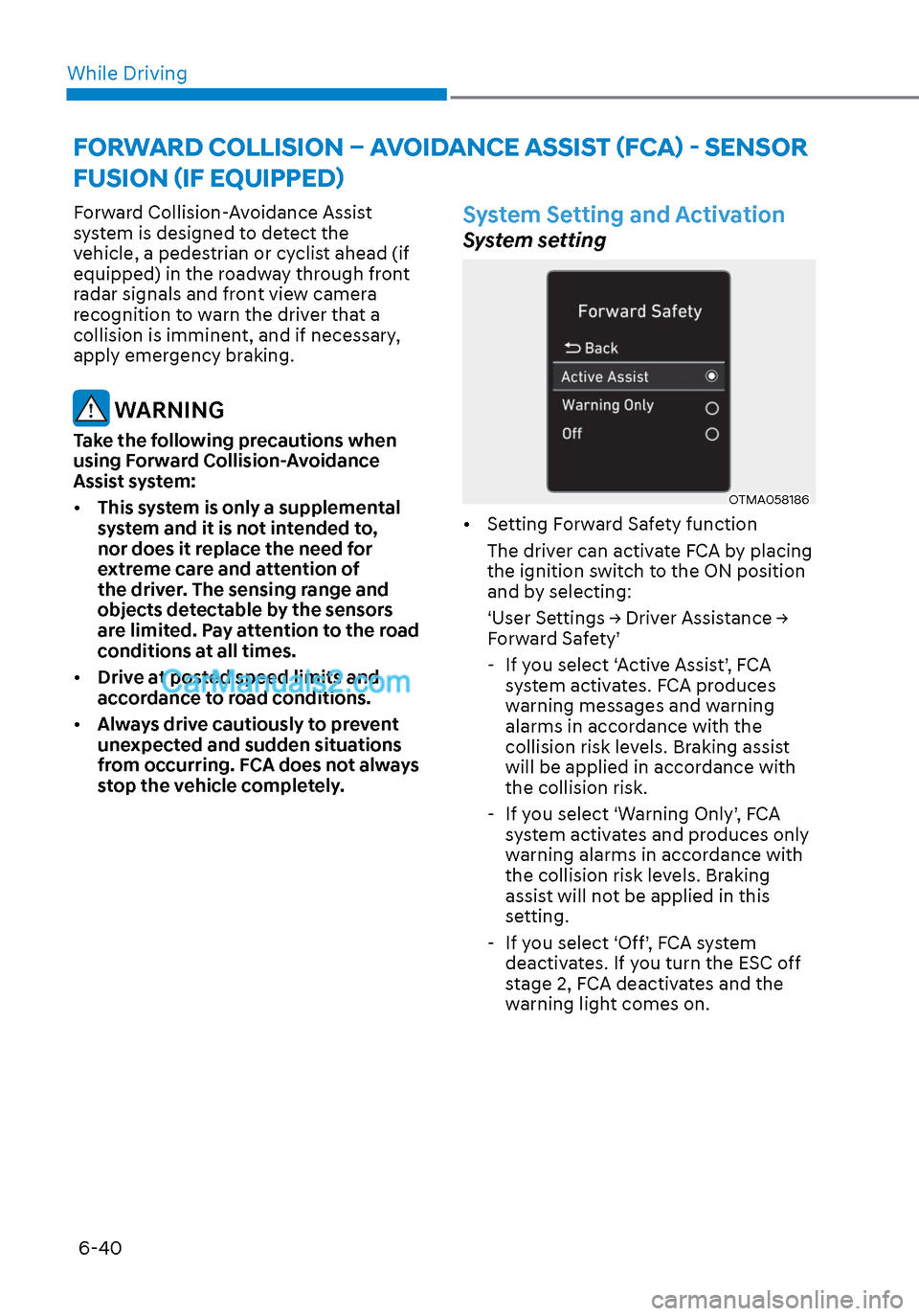
• Setting Forward Safety function
The driver can activate FCA by placing
the ignition switch to the ON position
and by selecting:
‘User Settings → Driver Assistance →
Forward Safety’ - If you select ‘Active Assist’, FCA system activates. FCA produces
warning messages and warning
alarms in accordance with the
collision risk levels. Braking assist
will be applied in accordance with
the collision risk.
- If you select ‘Warning Only’, FCA system activates and produces only
warning alarms in accordance with
the collision risk levels. Braking
assist will not be applied in this
setting.
- If you select ‘Off’, FCA system deactivates. If you turn the ESC off
stage 2, FCA deactivates and the
warning light comes on.
FORWARD COLLISION – AVOIDANCE ASSIST (FCA) - SENSOR
FUSION (IF EQUIPPED)
Page 329 of 537
06
6-45
FCA Sensor
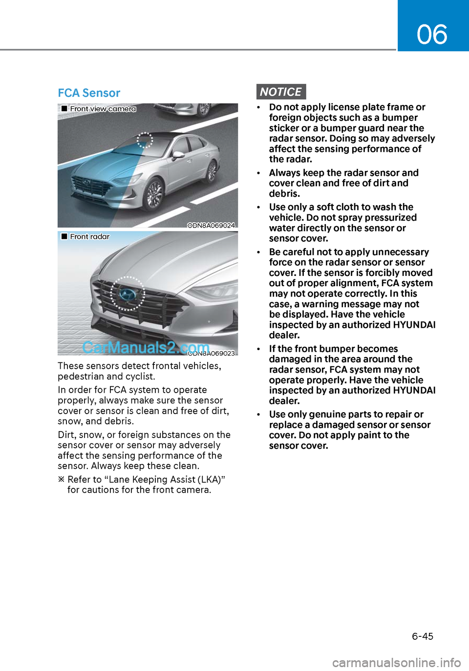
Front view cameraFront view camera
ODN8A069024ODN8A069024
Front radarFront radar
ODN8A069023ODN8A069023
These sensors detect frontal vehicles,
pedestrian and cyclist.
In order for FCA system to operate
properly, always make sure the sensor
cover or sensor is clean and free of dirt,
snow, and debris.
Dirt, snow, or foreign substances on the
sensor cover or sensor may adversely
affect the sensing performance of the
sensor. Always keep these clean.
Refer to “Lane Keeping Assist (LKA)” for cautions for the front camera.
NOTICE
• Do not apply license plate frame or
foreign objects such as a bumper
sticker or a bumper guard near the
radar sensor. Doing so may adversely
affect the sensing performance of
the radar.
• Always keep the radar sensor and
cover clean and free of dirt and
debris.
• Use only a soft cloth to wash the
vehicle. Do not spray pressurized
water directly on the sensor or
sensor cover.
• Be careful not to apply unnecessary
force on the radar sensor or sensor
cover. If the sensor is forcibly moved
out of proper alignment, FCA system
may not operate correctly. In this
case, a warning message may not
be displayed. Have the vehicle
inspected by an authorized HYUNDAI
dealer.
• If the front bumper becomes
damaged in the area around the
radar sensor, FCA system may not
operate properly. Have the vehicle
inspected by an authorized HYUNDAI
dealer.
• Use only genuine parts to repair or
replace a damaged sensor or sensor
cover. Do not apply paint to the
sensor cover.