tow HYUNDAI SONATA 2022 User Guide
[x] Cancel search | Manufacturer: HYUNDAI, Model Year: 2022, Model line: SONATA, Model: HYUNDAI SONATA 2022Pages: 546, PDF Size: 51.21 MB
Page 191 of 546
05
5-61
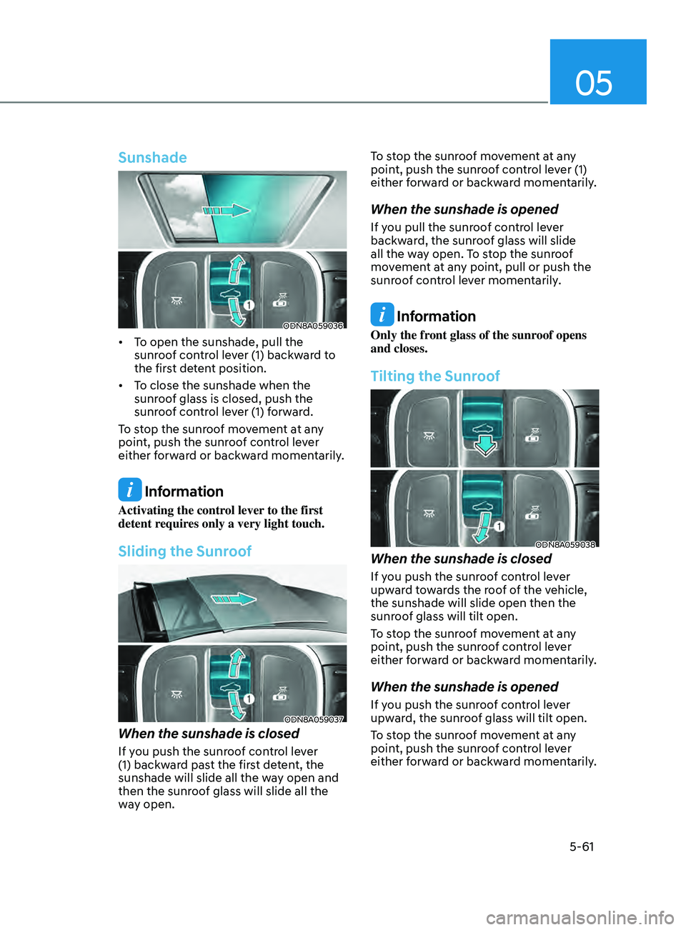
Sunshade
ODN8A059036
• To open the sunshade, pull the sunroof control lever (1) backward to
the first detent position.
• To
close the sunshade when the
sunr
oof glass is closed, push the
sunroof control lever (1) forward.
To stop the sunroof movement at any
point, push the sunroof control lever
either forward or backward momentarily.
Information
Activating the control lever to the first
detent requires only a very light touch.
Sliding the Sunroof
ODN8A059037
When the sunshade is closed
If you push the sunroof control lever
(1) backward past the first detent, the
sunshade will slide all the way open and
then the sunroof glass will slide all the
way open. To stop the sunroof movement at any
point, push the sunroof control lever (1)
either forward or backward momentarily.
When the sunshade is opened
If you pull the sunroof control lever
backward, the sunroof glass will slide
all the way open. To stop the sunroof
movement at any point, pull or push the
sunroof control lever momentarily.
Information
Only the front glass of the sunroof opens
and closes.
Tilting the Sunroof
ODN8A059038
When the sunshade is closed
If you push the sunroof control lever
upward towards the roof of the vehicle,
the sunshade will slide open then the
sunroof glass will tilt open.
To stop the sunroof movement at any
point, push the sunroof control lever
either forward or backward momentarily.
When the sunshade is opened
If you push the sunroof control lever
upward, the sunroof glass will tilt open.
To stop the sunroof movement at any
point, push the sunroof control lever
either forward or backward momentarily.
Page 205 of 546
05
5-75
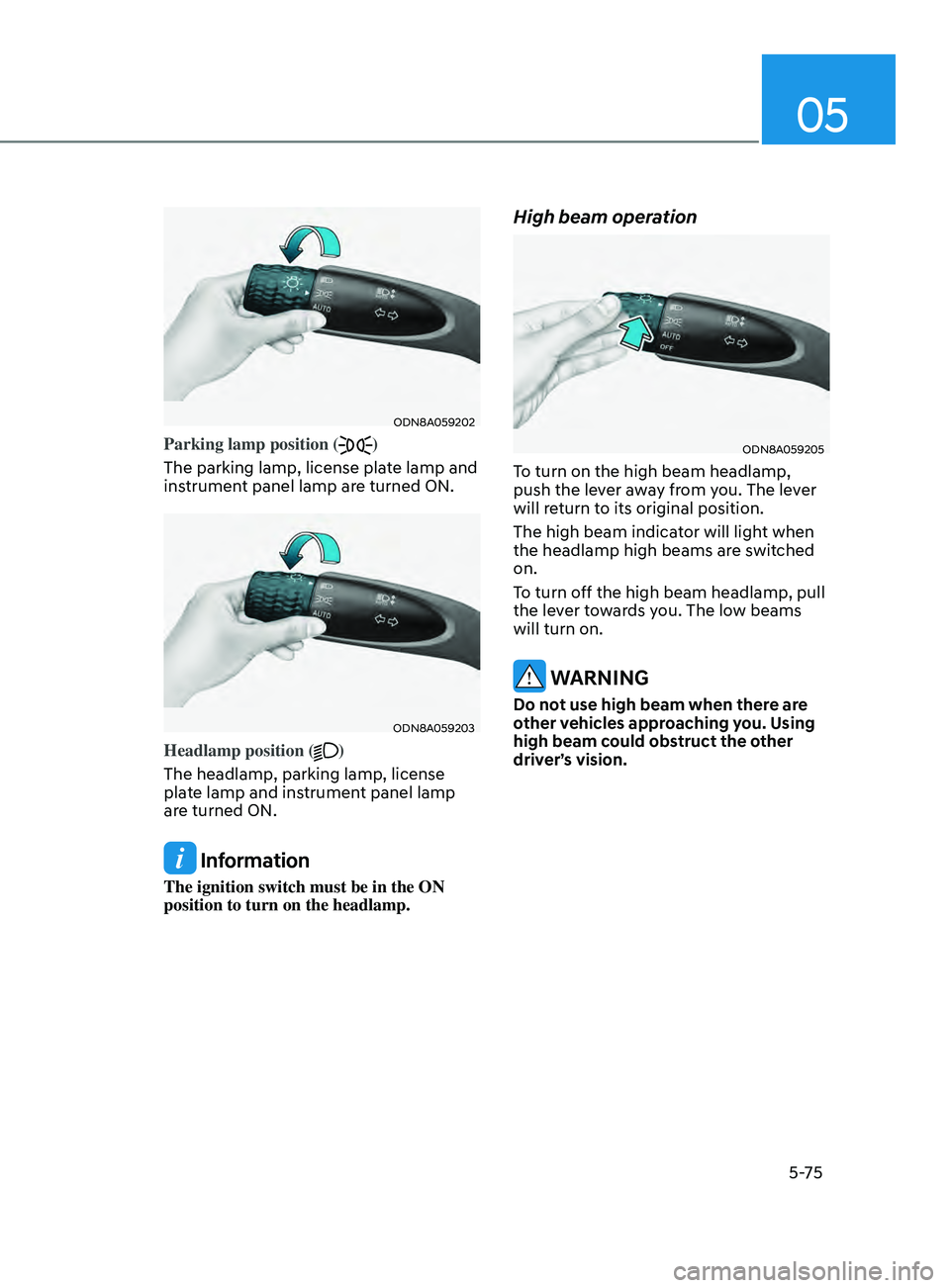
ODN8A059202
Parking lamp position ()
The parking lamp, license plate lamp and
instrument panel lamp are turned ON.
ODN8A059203
Headlamp position ()
The headlamp, parking lamp, license
plate lamp and instrument panel lamp
are turned ON.
Information
The ignition switch must be in the ON
position to turn on the headlamp.
High beam operation
ODN8A059205
To turn on the high beam headlamp,
push the lever away from you. The lever
will return to its original position.
The high beam indicator will light when
the headlamp high beams are switched
on.
To turn off the high beam headlamp, pull
the lever towards you. The low beams
will turn on.
WARNING
Do not use high beam when there are
other vehicles approaching you. Using
high beam could obstruct the other
driver’s vision.
Page 206 of 546
Convenient Features
5 -76
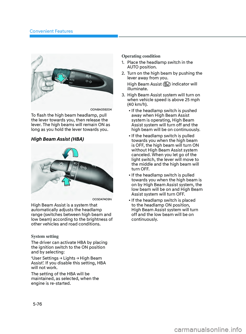
ODN8A059204
To flash the high beam headlamp, pull
the lever towards you, then release the
lever. The high beams will remain ON as
long as you hold the lever towards you.
High Beam Assist (HBA)
OOS047409N
High Beam Assist is a system that
automatically adjusts the headlamp
range (switches between high beam and
low beam) according to the brightness of
other vehicles and road conditions.
System setting
The driver can activate HBA by placing
the ignition switch to the ON position
and by selecting:
‘User Settings → Lights → High Beam
Assis
t’. If you disable this setting, HBA
will not work.
The setting of the HBA will be
maintained, as selected, when the
engine is re-started. Operating condition
1.
Place the headlamp s
witch in the
AUTO position.
2.
T
urn on the high beam by pushing the
lever away from you.
High Beam Assist (
) indicator will
illuminate.
3.
High Beam Assis
t system will turn on
when vehicle speed is above 25 mph
(40 km/h).
• If the headlamp switch is pushed
away when High Beam Assist
system is operating, High Beam
Assist system will turn off and the
high beam will be on continuously.
• If the headlamp switch is pulled
towards you when the high beam
is OFF, the high beam will turn ON
without High Beam Assist system
canceled. When you let go of the
light switch, the lever will move to
the middle and the high beam will
turn OFF.
• If the headlamp switch is pulled
towards you when the high beam is
on by High Beam Assist system, the
low beam will be on and High Beam
Assist system will turn OFF.
• If the headlamp switch is placed
to the headlamp ON position,
High Beam Assist system will turn
off and the low beam will be on
continuously.
Page 208 of 546
Convenient Features5-78
2. When the High Beam Assis t camera
is adversely affected by an external
condition. Such examples may
include:
• When the vehicle’s headlamps
have been damaged or not
repaired properly.
• When the vehicle headlamps are
not aimed properly.
• When the vehicle is driven on a
narrow curved road or rough road
• When the vehicle is driven on an
uphill road or downhill road
• When only part of the vehicle in
front is visible on a crossroad or
curved road.
• When there is a traffic light,
reflecting sign, flashing sign or
mirror.
• When the road conditions are bad
such as being wet or covered with
snow.
• When a vehicle suddenly appears
from a curve.
• When the vehicle is tilted from a
flat tire or being towed.
• When Lane Keeping Assist system
warning light illuminates.
• When the light from the on-coming
or front vehicle is not detected
because of exhaust fume, smoke,
fog, snow, etc.
• When the front window is covered
with foreign matters such as ice,
dust, fog, or is damaged.
3.
When the f
orward visibility is poor.
Such examples may include:
• When the headlamps of an on-
coming vehicle or a vehicle in front
is not detected due to poor outside
visibility (smog, smoke, dust, fog,
heavy rain, snow, etc.).
• When the windshield visibility is
poor. WARNING
• Do not attempt to disassemble
the front view camera without the
assistance of an authorized HYUNDAI
dealer technician. If the front camera
is removed for any reason, the
system may need to be re-calibrated.
Have the system inspected by an
authorized HYUNDAI dealer.
• If the windshield of your vehicle is
replaced, most likely the front view
camera will need to be re-calibrated.
If this occurs, have your vehicle
inspected and have the system re-
calibrated by an authorized HYUNDAI
dealer.
• Be careful that water doesn’t get into
High Beam Assist unit and do not
remove or damage related parts of
High Beam Assist system.
• Do not place objects on the crash
pad that reflect light such as mirrors,
white paper, etc. The system may
malfunction if sunlight is reflected.
• At times, High Beam Assist system
may not work properly. The system
is for your convenience only. It is the
responsibility of the driver for safe
driving practices and always check
the road conditions for your safety.
• When the system does not operate
normally, change the headlamp
position manually between the high
beam and low beam.
Page 214 of 546
Convenient Features5-84
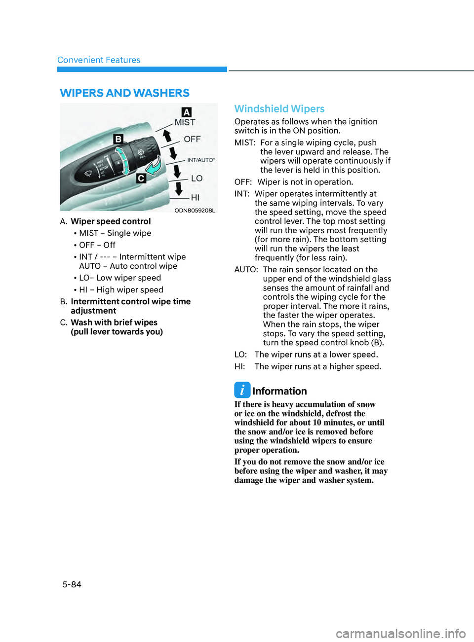
Wipers AnD WAsher s
ODN8059208L
A. Wiper speed control
• MIST – Single wipe
• OFF – Off
• INT / --- – Intermittent wipe
AUTO – Auto control wipe
• LO– Low wiper speed
• HI – High wiper speed
B.
In
termittent control wipe time
adjustment
C.
W
ash with brief wipes
(pull lever towards you)
Windshield Wipers
Operates as follows when the ignition
switch is in the ON position.
MIST: For a single wiping cycle, push the lever upward and release. The
wipers will operate continuously if
the lever is held in this position.
OFF: Wiper is not in operation.
INT: Wiper operates intermittently at the same wiping intervals. To vary
the speed setting, move the speed
control lever. The top most setting
will run the wipers most frequently
(for more rain). The bottom setting
will run the wipers the least
frequently (for less rain).
AUTO: The rain sensor located on the upper end of the windshield glass
senses the amount of rainfall and
controls the wiping cycle for the
proper interval. The more it rains,
the faster the wiper operates.
When the rain stops, the wiper
stops. To vary the speed setting,
turn the speed control knob (B).
LO: The wiper runs at a lower speed.
HI: The wiper runs at a higher speed.
Information
If there is heavy accumulation of snow
or ice on the windshield, defrost the
windshield for about 10 minutes, or until
the snow and/or ice is removed before
using the windshield wipers to ensure
proper operation.
If you do not remove the snow and/or ice
before using the wiper and washer, it may
damage the wiper and washer system.
Page 215 of 546
05
5-85
Information
If the wiper switch is set in AUTO mode
when Engine Start/Stop button is in the
ON position, the wiper will operate once to
perform a self-check of the system. Set the
wiper to the OFF position when the wiper
is not in use.
WARNING
To avoid personal injury from the
windshield wipers, when the engine
is running and the windshield wiper
switch is placed in the AUTO mode:
•
Do no
t touch the upper end of the
windshield glass facing the rain
sensor.
•
Do no
t wipe the upper end of the
windshield glass with a damp or wet
cloth.
•
Do no
t put pressure on the
windshield glass.
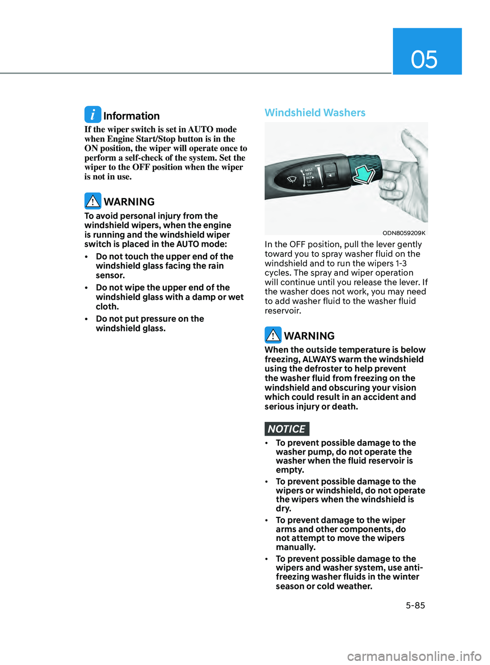
Windshield Washers
ODN8059209K
In the OFF position, pull the lever gently
toward you to spray washer fluid on the
windshield and to run the wipers 1-3
cycles. The spray and wiper operation
will continue until you release the lever. If
the washer does not work, you may need
to add washer fluid to the washer fluid
reservoir.
WARNING
When the outside temperature is below
freezing, ALWAYS warm the windshield
using the defroster to help prevent
the washer fluid from freezing on the
windshield and obscuring your vision
which could result in an accident and
serious injury or death.
NOTICE
• To prevent possible damage to the
washer pump, do not operate the
washer when the fluid reservoir is
empty.
• To prevent possible damage to the
wipers or windshield, do not operate
the wipers when the windshield is
dry.
• To prevent damage to the wiper
arms and other components, do
not attempt to move the wipers
manually.
• To prevent possible damage to the
wipers and washer system, use anti-
freezing washer fluids in the winter
season or cold weather.
Page 224 of 546
Convenient Features
5-94
• Outside air temperature is hot or cold.
• The wind is either strong (over 12 mph
(20 km/h)) or blowing perpendicular
to the rear bumper.
• Objects generating excessive
noise, such as vehicle horns, loud
motorcycle engines, or truck air
brakes, are near the vehicle.
• An ultrasonic sensor with a similar
frequency is near the vehicle.
• There is ground height difference
between the vehicle and the
pedestrian.
• The image of the pedestrian in the
rear view camera is indistinguishable
from the background.
• The pedestrian is near the rear edge of
the vehicle.
• The pedestrian is not standing upright.
• The pedestrian is either too short or
too tall for the system to recognize.
• The pedestrian is wearing clothes that
are hard for the system to recognize.
• The pedestrian is wearing a cloth that
does not reflect ultrasound well.
• The size, thickness, height, or shape of
the object does not reflect ultrasound
well (e.g., pole, bush, curbs, carts,
edge of a wall, etc.).
• The pedestrian or the object is
moving.
• The pedestrian or the object is very
close to the rear of the vehicle.
• A wall is behind the pedestrian or the
object.
• The object is not at the rear center of
the vehicle.
• The plane of the obstacle is not
parallel to the rear bumper.
• The road is slippery or inclined.
• The driver backs up the vehicle
immediately after shifting to R
(Reverse).
• The driver accelerates or turns the
vehicle. Reverse Parking Collision-Avoidance
Assist system may alert the driver or
apply brake power unnecessarily under
the following conditions even if there are
“no” pedestrians or objects.
•
Any non-factory equipment or
accessories have been installed.
• The condition of the vehicle is
unstable due to an accident or other
causes.
• The height of the bumper or the
sensor installation has been modified.
• The bumper height has changed due
to heavy loads, tire pressure change,
etc.
• The rear view camera or the ultrasonic
sensor(s) is stained with foreign
matter, such as snow, dirt, etc.
• The pattern on the road is mistaken
for a pedestrian.
• There is a shadow or a light reflecting
on the ground.
• Pedestrians or objects are around the
path of the vehicle.
• Objects generating excessive
noise, such as vehicle horns, loud
motorcycle engines, or truck air
brakes, are near the vehicle.
• The vehicle is backing towards a
narrow passage or parking space.
• The vehicle is backing towards an
uneven road surface, such as unpaved
road, gravel, bump, gradient, etc.
• A trailer is attached to the vehicle
Page 251 of 546
05
5-121
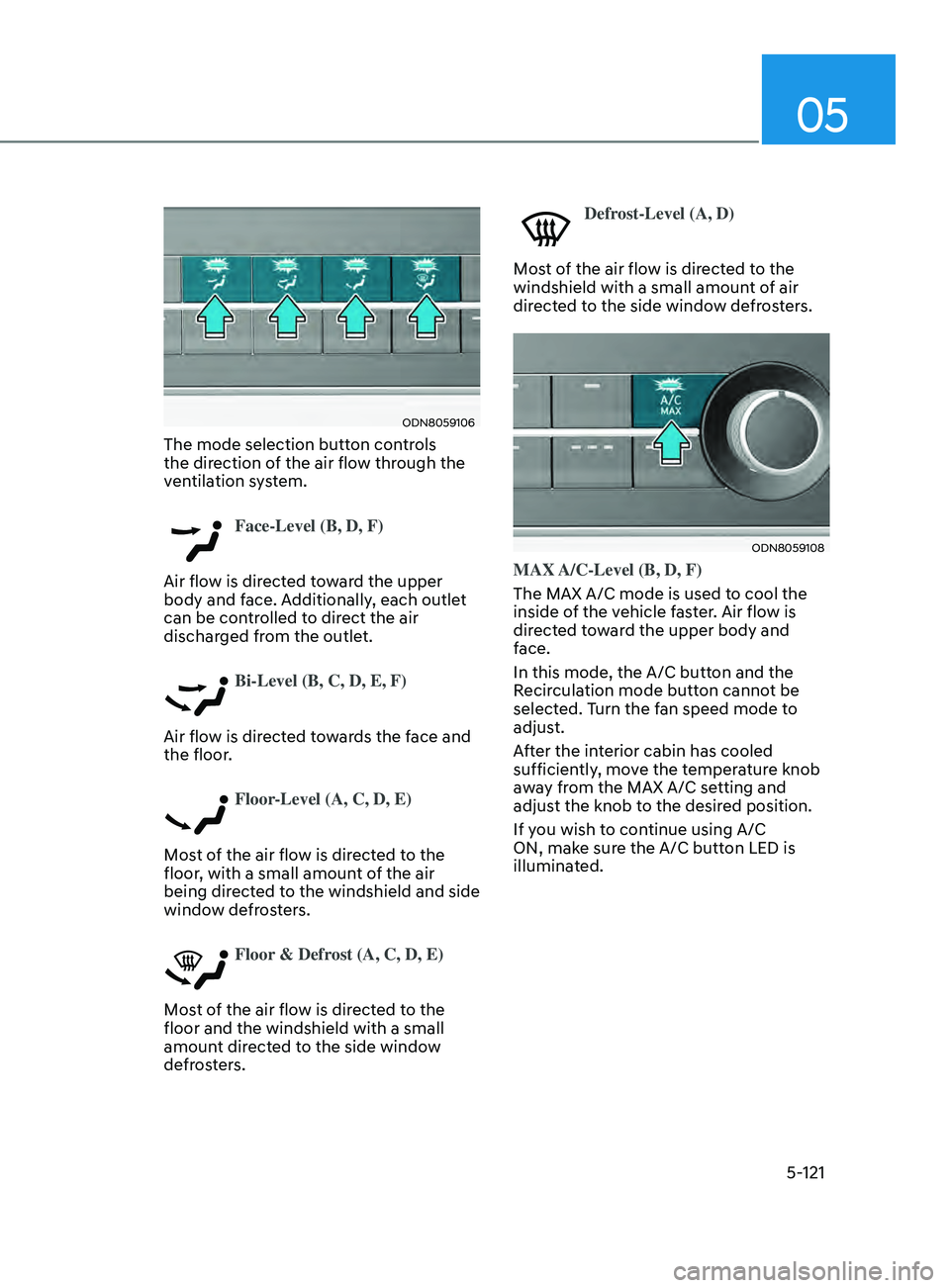
ODN8059106
The mode selection button controls
the direction of the air flow through the
ventilation system.
Face-Level (B, D, F)
Air flow is directed toward the upper
body and face. Additionally, each outlet
can be controlled to direct the air
discharged from the outlet.
Bi-Level (B, C, D, E, F)
Air flow is directed towards the face and
the floor.
Floor-Level (A, C, D, E)
Most of the air flow is directed to the
floor, with a small amount of the air
being directed to the windshield and side
window defrosters.
Floor & Defrost (A, C, D, E)
Most of the air flow is directed to the
floor and the windshield with a small
amount directed to the side window
defrosters.
Defrost-Level (A, D)
Most of the air flow is directed to the
windshield with a small amount of air
directed to the side window defrosters.
ODN8059108
MAX A/C-Level (B, D, F)
The MAX A/C mode is used to cool the
inside of the vehicle faster. Air flow is
directed toward the upper body and
face.
In this mode, the A/C button and the
Recirculation mode button cannot be
selected. Turn the fan speed mode to
adjust.
After the interior cabin has cooled
sufficiently, move the temperature knob
away from the MAX A/C setting and
adjust the knob to the desired position.
If you wish to continue using A/C
ON, make sure the A/C button LED is
illuminated.
Page 261 of 546
05
5-131
ODN8059129L
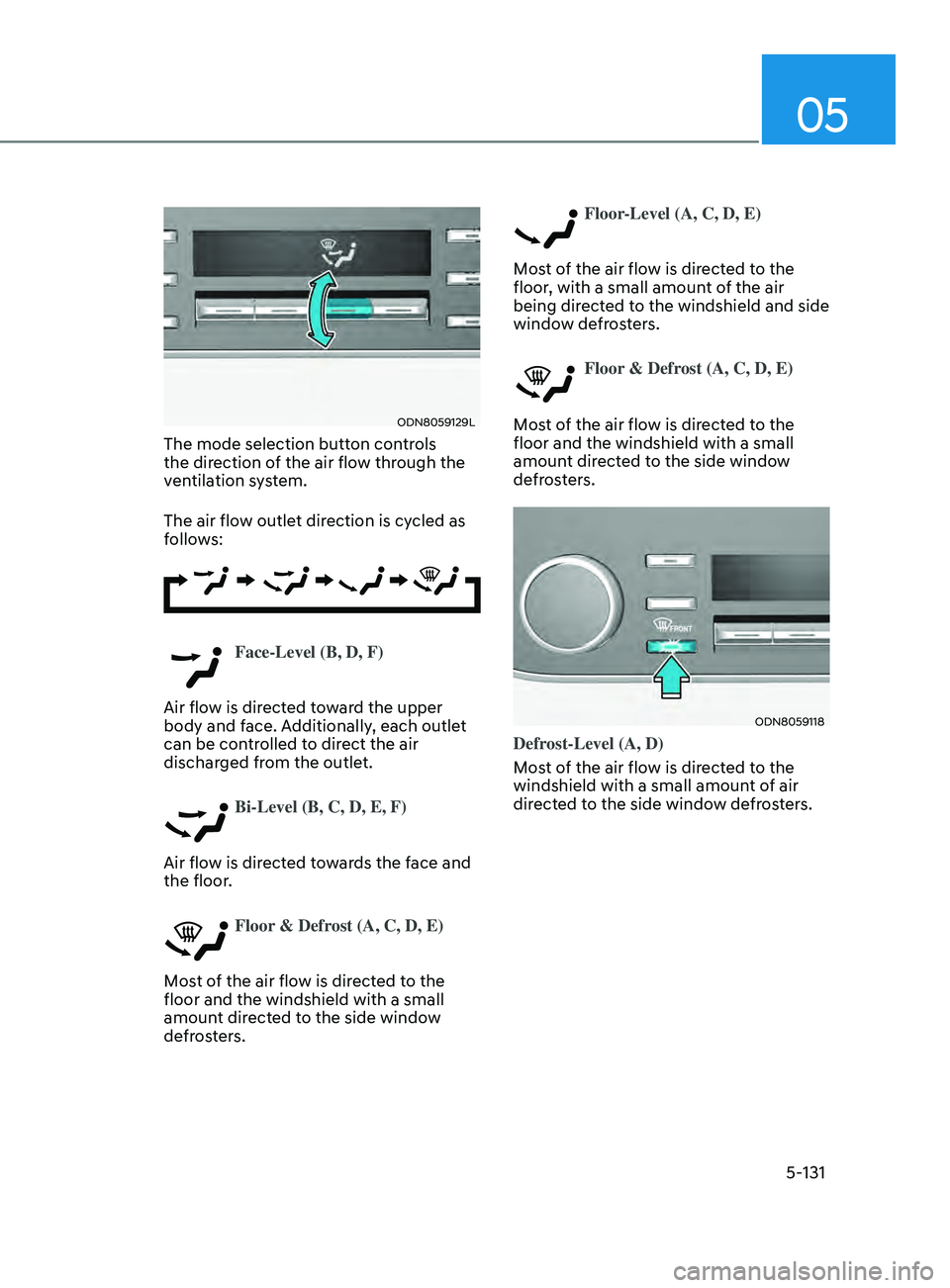
The mode selection button controls
the direction of the air flow through the
ventilation system.
The air flow outlet direction is cycled as
follows:
Face-Level (B, D, F)
Air flow is directed toward the upper
body and face. Additionally, each outlet
can be controlled to direct the air
discharged from the outlet.
Bi-Level (B, C, D, E, F)
Air flow is directed towards the face and
the floor.
Floor & Defrost (A, C, D, E)
Most of the air flow is directed to the
floor and the windshield with a small
amount directed to the side window
defrosters.
Floor-Level (A, C, D, E)
Most of the air flow is directed to the
floor, with a small amount of the air
being directed to the windshield and side
window defrosters.
Floor & Defrost (A, C, D, E)
Most of the air flow is directed to the
floor and the windshield with a small
amount directed to the side window
defrosters.
ODN8059118
Defrost-Level (A, D)
Most of the air flow is directed to the
windshield with a small amount of air
directed to the side window defrosters.
Page 287 of 546
Highway Driving Assist (HDA) ...................................................................6- 122System Setting and Operation ........................................................................\
.....6- 123
Warning Message ........................................................................\
.......................... 6-125
Rear Cross-Traffic Collision Warning (RCCW) /
Rear Cross-Traffic Collision-Avoidance Assist (RCCA)
...........................6-128
System Description ........................................................................\
....................... 6- 128
System Setting and Activation ........................................................................\
..... 6-129
Warning and System Control
........................................................................\
........ 6-131
Detecting Sensors
........................................................................\
.........................6-134
Limitations of the System
........................................................................\
............. 6-135
Special Driving Conditions ........................................................................\
6- 140Hazardous Driving Conditions ........................................................................\
....6- 140
Rocking the Vehicle ........................................................................\
..................... 6-140
Smooth Cornering
........................................................................\
......................... 6-141
Driving at Night
........................................................................\
............................. 6-141
Driving in the Rain
........................................................................\
......................... 6-141
Driving in Flooded Areas
........................................................................\
............... 6-142
Highway Driving
........................................................................\
............................ 6-142
Winter Driving ........................................................................\
....................6- 143Snow or Icy Conditions ........................................................................\
.................6-143
Win ter Precautions ........................................................................\
....................... 6-144
Vehicle load limit........................................................................\
................ 6-146
Tire Loading Information Label ........................................................................\
...6- 146
Trailer Towing ........................................................................\
......................6- 151
Lane Keeping Assist (LKA) ........................................................................\
..6-59LKA Operation ........................................................................\
................................ 6-61
LKA System Function Change ........................................................................\
....... 6-61
Warning Light and Message ........................................................................\
.......... 6-64
Limitations of the System ........................................................................\
.............. 6-65
Blind-Spot Collision Warning (BCW) /
Blind-Spot Collision-Avoidance Assist (BCA) ............................................6-67
System Description ........................................................................\
........................ 6-67
System Setting and Activation ........................................................................\
...... 6-68
Warning and System Control ........................................................................\
......... 6-70
Detecting Sensors
(Front view camera and Rear corner radar).......................................................... 6-72
Limitations of the System ........................................................................\
.............. 6-75
Declaration of Conformity ........................................................................\
...6-79The radio frequency components (Rear Corner Radar) complies: ..................... 6-79
Safe Exit Assist (SEA) ........................................................................\
.........6-80Function settings ........................................................................\
............................ 6-81
Function operation ........................................................................\
......................... 6-82
Function malfunction and limitations ................................................................... 6-84
Driver Attention Warning (DAW) ................................................................ 6-86System Setting and Operation ........................................................................\
...... 6-86
Resetting the System ........................................................................\
..................... 6-88
System Standby ........................................................................\
.............................. 6-89
System Malfunction ........................................................................\
....................... 6-89
Leading Vehicle Departure Alert ........................................................................\
... 6-91
Blind-Spot View Monitor (BVM) ................................................................. 6-94
Smart cruise control (SCC) ........................................................................\
. 6-95
Smart Cruise Control Switch ........................................................................\
......... 6-96
To Convert to Cruise Control Mode ...................................................................... 6-96
Smart Cruise Control Speed ........................................................................\
.......... 6-97
Smart Cruise Control Vehicle-to-Vehicle Distance ............................................ 6-103
Limitations of the System ........................................................................\
............ 6-108
Navigation-Based Smart Cruise Control ..................................................6-112System Setting and Operation ........................................................................\
..... 6-113
Lane Following Assist (LFA) ....................................................................... 6-116LFA Operation ........................................................................\
................................ 6-118
Warning Message ........................................................................\
.......................... 6-118
Limitations of the System ........................................................................\
............ 6-120
6
6. While Driving