light Hyundai Sonata
[x] Cancel search | Manufacturer: HYUNDAI, Model Year: , Model line: , Model:Pages: 380, PDF Size: 7.97 MB
Page 108 of 380
Features of your vehicle28
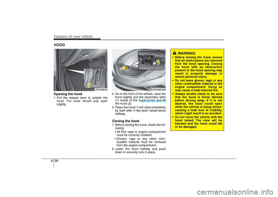
4Opening the hood 1. Pull the release lever to unlatch the
hood. The hood should pop open
slightly. 2. Go to the front of the vehicle, raise the
hood slightly, pull the secondary latch
(1) inside of the hood center and lift
the hood (2).
3. Raise the hood. It will raise completely by itself after it has been raised about
halfway.
Closing the hood1. Before closing the hood, check the fol-lowing:
• All filler caps in engine compartment must be correctly installed.
• Gloves, rags or any other com- bustible material must be removed
from the engine compartment.
2. Lower the hood halfway and push down to securely lock in place.
HOOD
OYF049018
OYF049019N
WARNING
• Before closing the hood, ensurethat all obstructions are removed
from the hood opening. Closing
the hood with an obstruction
present in the hood opening may
result in property damage or
severe personal injury.
• Do not leave gloves, rags or any other combustible material in the
engine compartment. Doing so
may cause a heat-induced fire.
• Always double check to be sure that the hood is firmly latched
before driving away. If it is not
latched, the hood could open
while the vehicle is being driven,
causing a total loss of visibility,
which might result in an accident.
• Do not move the vehicle with the hood raised. The view will be
blocked and the hood could fall
or be damaged.
YF HMA 4-103.QXP 12/24/2009 5:11 PM Page 28
Page 109 of 380
429
Features of your vehicle
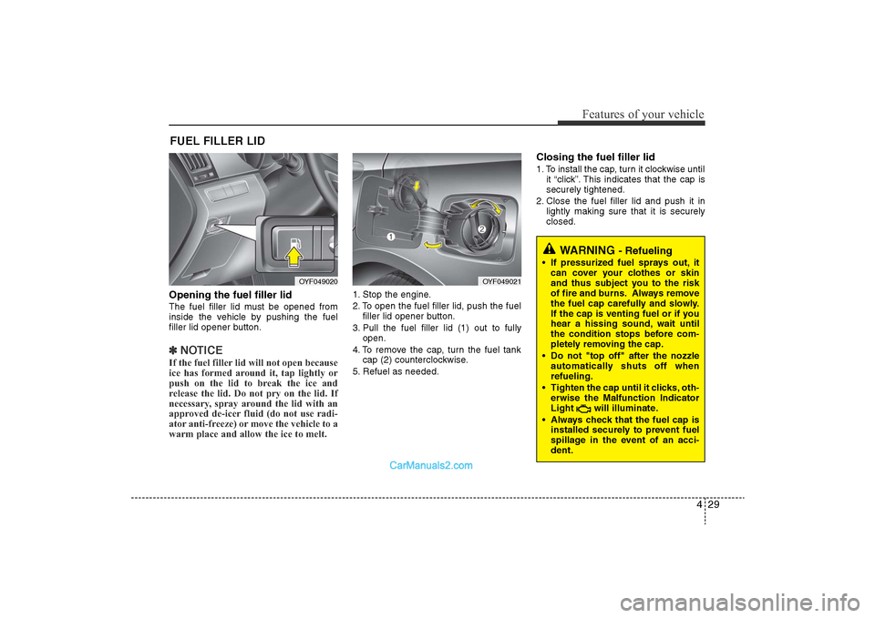
Opening the fuel filler lidThe fuel filler lid must be opened from
inside the vehicle by pushing the fuel
filler lid opener button.✽NOTICEIf the fuel filler lid will not open because
ice has formed around it, tap lightly or
push on the lid to break the ice and
release the lid. Do not pry on the lid. If
necessary, spray around the lid with an
approved de-icer fluid (do not use radi-
ator anti-freeze) or move the vehicle to a
warm place and allow the ice to melt.
1. Stop the engine.
2. To open the fuel filler lid, push the fuel
filler lid opener button.
3. Pull the fuel filler lid (1) out to fully open.
4. To remove the cap, turn the fuel tank cap (2) counterclockwise.
5. Refuel as needed.
Closing the fuel filler lid1. To install the cap, turn it clockwise until it “click”. This indicates that the cap is
securely tightened.
2. Close the fuel filler lid and push it in lightly making sure that it is securely
closed.
FUEL FILLER LID
OYF049020
OYF049021
WARNING
- Refueling
• If pressurized fuel sprays out, itcan cover your clothes or skin
and thus subject you to the risk
of fire and burns. Always remove
the fuel cap carefully and slowly.
If the cap is venting fuel or if you
hear a hissing sound, wait until
the condition stops before com-
pletely removing the cap.
• Do not "top off" after the nozzle automatically shuts off when
refueling.
• Tighten the cap until it clicks, oth- erwise the Malfunction Indicator
Light will illuminate.
• Always check that the fuel cap is installed securely to prevent fuel
spillage in the event of an acci-
dent.
YF HMA 4-103.QXP 12/24/2009 5:11 PM Page 29
Page 110 of 380
Features of your vehicle30
4
(Continued)
Use only approved portable plas-
tic fuel containers designed to
carry and store gasoline.
• Do not use cellular phones while refueling. Electric current and/or
electronic interference from cel-
lular phones can potentially
ignite fuel vapors causing a fire.
• When refueling, always shut the engine off. Sparks produced by
electrical components related to
the engine can ignite fuel vapors
causing a fire. Once refueling is
complete, check to make sure the
filler cap and filler door are
securely closed, before starting
the engine.
• DO NOT use matches or a lighter and DO NOT SMOKE or leave a lit
cigarette in your vehicle while at
a gas station especially during
refueling. Automotive fuel is
highly flammable and can, when
ignited, result in fire.
(Continued)
(Continued)
• Do not get back into a vehicleonce you have begun refueling
since you can generate static
electricity by touching, rubbing
or sliding against any item or fab-
ric (polyester, satin, nylon, etc.)
capable of producing static elec-
tricity. Static electricity discharge
can ignite fuel vapors resulting in
rapid burning. If you must re-
enter the vehicle, you should
once again eliminate potentially
dangerous static electricity dis-
charge by touching a metal part
of the vehicle, away from the fuel
filler neck, nozzle or other gaso-
line source.
• When using an approved portable fuel container, be sure to
place the container on the
ground prior to refueling. Static
electricity discharge from the
container can ignite fuel vapors
causing a fire. Once refueling has
begun, contact with the vehicle
should be maintained until the
filling is complete.
(Continued)
WARNING -
Refueling dan-
gers
Automotive fuels are flammable
materials. When refueling, please
note the following guidelines care-
fully. Failure to follow these guide-
lines may result in severe personal
injury, severe burns or death by fire
or explosion.
• Read and follow all warningsposted at the gas station facility.
• Before refueling, note the loca- tion of the Emergency Gasoline
Shut-Off, if available, at the gas
station facility.
• Before touching the fuel nozzle, you should eliminate potentially
dangerous static electricity dis-
charge by touching another metal
part of the vehicle, a safe dis-
tance away from the fuel filler
neck, nozzle, or other gas source.
(Continued)
YF HMA 4-103.QXP 12/24/2009 5:11 PM Page 30
Page 111 of 380
431
Features of your vehicle
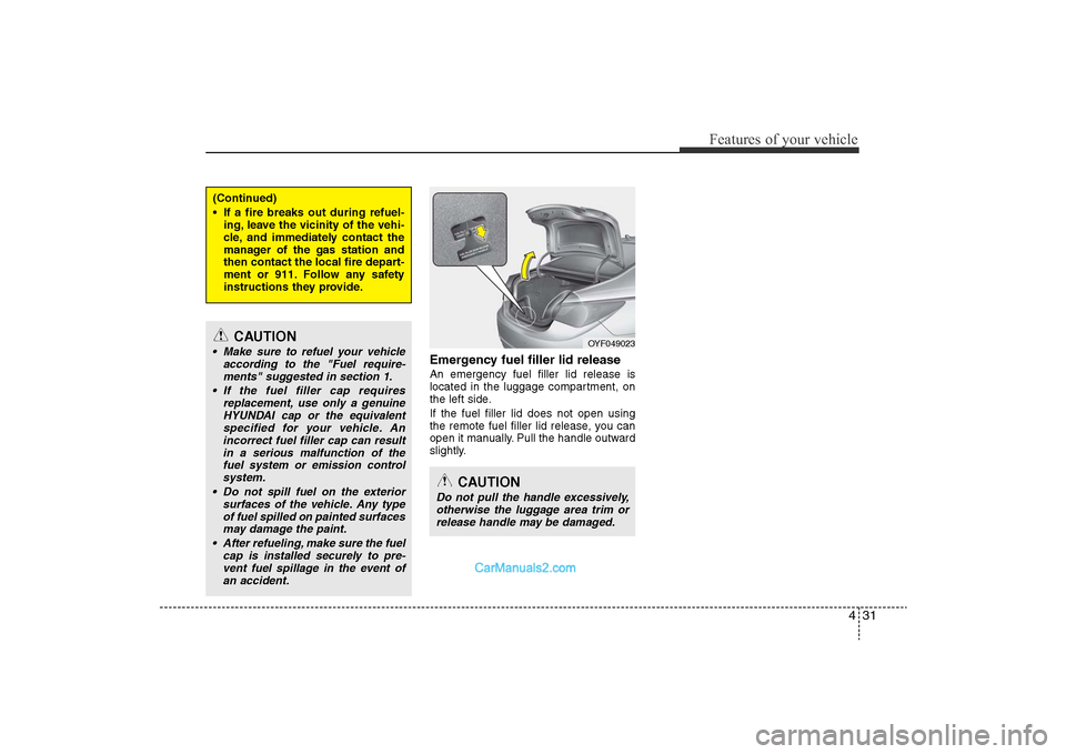
Emergency fuel filler lid releaseAn emergency fuel filler lid release is
located in the luggage compartment, on
the left side.
If the fuel filler lid does not open using
the remote fuel filler lid release, you can
open it manually. Pull the handle outward
slightly.
(Continued)
• If a fire breaks out during refuel-ing, leave the vicinity of the vehi-
cle, and immediately contact the
manager of the gas station and
then contact the local fire depart-
ment or 911. Follow any safety
instructions they provide.
CAUTION
• Make sure to refuel your vehicle according to the "Fuel require-ments" suggested in section 1.
• If the fuel filler cap requires replacement, use only a genuineHYUNDAI cap or the equivalentspecified for your vehicle. Anincorrect fuel filler cap can resultin a serious malfunction of thefuel system or emission control system.
• Do not spill fuel on the exterior surfaces of the vehicle. Any typeof fuel spilled on painted surfacesmay damage the paint.
• After refueling, make sure the fuel cap is installed securely to pre-vent fuel spillage in the event of an accident.
CAUTION
Do not pull the handle excessively,otherwise the luggage area trim or release handle may be damaged.
OYF049023
YF HMA 4-103.QXP 12/24/2009 5:11 PM Page 31
Page 114 of 380
Features of your vehicle34
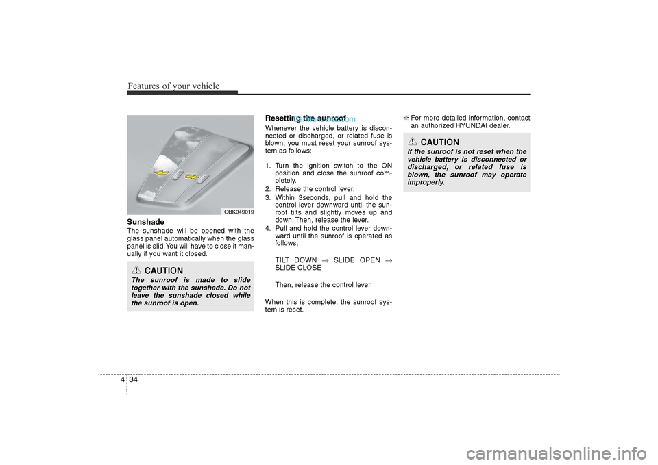
4SunshadeThe sunshade will be opened with the
glass panel automatically when the glass
panel is slid. You will have to close it man-
ually if you want it closed.
Resetting the sunroofWhenever the vehicle battery is discon-
nected or discharged, or related fuse is
blown, you must reset your sunroof sys-
tem as follows:
1. Turn the ignition switch to the ON
position and close the sunroof com-
pletely.
2. Release the control lever.
3. Within 3seconds, pull and hold the control lever downward until the sun-
roof tilts and slightly moves up and
down. Then, release the lever.
4. Pull and hold the control lever down- ward until the sunroof is operated as
follows;
TILT DOWN �oSLIDE OPEN �o
SLIDE CLOSE
Then, release the control lever.
When this is complete, the sunroof sys-
tem is reset. ❈
For more detailed information, contact
an authorized HYUNDAI dealer.
CAUTION
The sunroof is made to slide
together with the sunshade. Do not leave the sunshade closed whilethe sunroof is open.
OBK049019
CAUTION
If the sunroof is not reset when thevehicle battery is disconnected ordischarged, or related fuse isblown, the sunroof may operateimproperly.
YF HMA 4-103.QXP 12/24/2009 5:11 PM Page 34
Page 115 of 380
435
Features of your vehicle
Electric power steering (EPS)The power steering uses a motor to
assist you in steering the vehicle. If the
engine is off or if the power steering sys-
tem becomes inoperative, the vehicle
may still be steered, but it will require
increased steering effort.
The motor driven power steering is con-
trolled by a power steering control unit
which senses the steering wheel torque
and vehicle speed to command the
motor.
The steering becomes heavier as the
vehicle’s speed increases and becomes
lighter as the vehicle’s speed decreases
for optimum steering control.
Should you notice any change in the
effort required to steer during normal
vehicle operation, have the power steer-
ing checked by an authorized HYUNDAI
dealer.
✽NOTICEThe following symptoms may occur dur-
ing normal vehicle operation:
• The EPS warning light does not illumi-
nate.
• The steering effort is high immediately after turning the ignition switch on.
This happens as the system performs
the EPS system diagnostics. When the
diagnostics is completed, the steering
wheel will return to its normal condi-
tion.
• A click noise may be heard from the EPS relay after the ignition switch is
turned to the ON or LOCK position.
• A motor noise may be heard when the vehicle is at a stop or at a low driving
speed.
• If the Electric Power Steering System does not operate normally, the warn-
ing light will illuminate on the instru-
ment cluster. The steering wheel may
become difficult to control or operate
abnormally. Take your vehicle to an
authorized HYUNDAI dealer and
have the vehicle checked as soon as
possible.
• When you operate the steering wheel in low temperature, abnormal noise
could occur. If temperature rises, the
noise will disappear. This is a normal
condition.
STEERING WHEEL
CAUTION
• If the Electric Power Steering
System does not operate normal-ly, the warning light will illuminateon the instrument cluster. Thesteering wheel may become diffi-cult to control or operate abnor- mally. Take your vehicle to anauthorized HYUNDAI dealer and have the vehicle checked as soonas possible.
• When you operate the steering wheel in low temperature, abnor-mal noise could occur. If tempera-ture rises, the noise will disap-pear. This is a normal condition.
YF HMA 4-103.QXP 12/24/2009 5:11 PM Page 35
Page 116 of 380
Features of your vehicle36
4Tilt steering Tilt steering allows you to adjust the
steering wheel before you drive. You can
also raise it to give your legs more room
when you exit and enter the vehicle.
The steering wheel should be positioned
so that it is comfortable for you to drive,
while permitting you to see the instru-
ment panel warning lights and gauges.
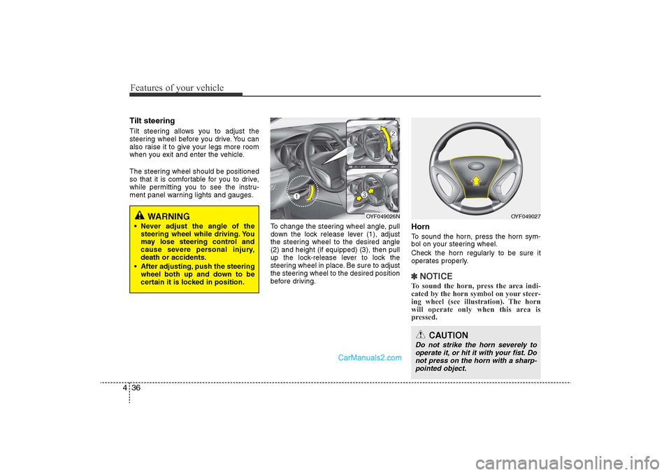
To change the steering wheel angle, pull
down the lock release lever (1), adjust
the steering wheel to the desired angle
(2) and height (if equipped) (3), then pull
up the lock-release lever to lock the
steering wheel in place. Be sure to adjust
the steering wheel to the desired position
before driving.
HornTo sound the horn, press the horn sym-
bol on your steering wheel.
Check the horn regularly to be sure it
operates properly.✽NOTICETo sound the horn, press the area indi-
cated by the horn symbol on your steer-
ing wheel (see illustration). The horn
will operate only when this area is
pressed.
OYF049026N
OYF049027
CAUTION
Do not strike the horn severely to
operate it, or hit it with your fist. Donot press on the horn with a sharp-pointed object.
WARNING
• Never adjust the angle of the steering wheel while driving. You
may lose steering control and
cause severe personal injury,
death or accidents.
• After adjusting, push the steering wheel both up and down to be
certain it is locked in position.
YF HMA 4-103.QXP 12/24/2009 5:12 PM Page 36
Page 117 of 380
437
Features of your vehicle
MIRRORS Inside rearview mirrorAdjust the rearview mirror so that the
center view through the rear window is
seen. Make this adjustment before you
start driving.
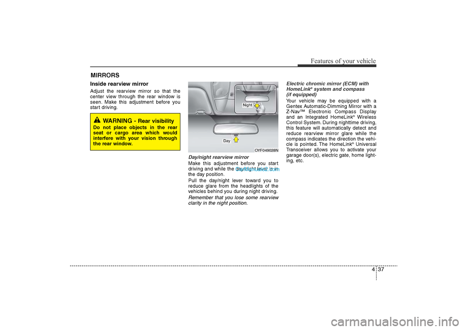
Day/night rearview mirror Make this adjustment before you start
driving and while the day/night lever is in
the day position.
Pull the day/night lever toward you to
reduce glare from the headlights of the
vehicles behind you during night driving.Remember that you lose some rearviewclarity in the night position. Electric chromic mirror (ECM) with
HomeLink
®system and compass
(if equipped)
Your vehicle may be equipped with a
Gentex Automatic-Dimming Mirror with a
Z-Nav™ Electronic Compass Display
and an Integrated HomeLink
®Wireless
Control System. During nighttime driving,
this feature will automatically detect and
reduce rearview mirror glare while the
compass indicates the direction the vehi-
cle is pointed. The HomeLink®Universal
Transceiver allows you to activate your
garage door(s), electric gate, home light-
ing, etc.
WARNING -
Rear visibility
Do not place objects in the rear
seat or cargo area which would
interfere with your vision through
the rear window.
OYF049028N
Day
Night
YF HMA 4-103.QXP 12/24/2009 5:12 PM Page 37
Page 118 of 380
Features of your vehicle38
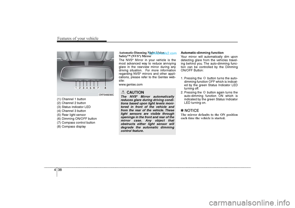
4(1) Channel 1 button
(2) Channel 2 button
(3) Status indicator LED
(4) Channel 3 button
(5) Rear light sensor
(6) Dimming ON/OFF button
(7) Compass control button
(8) Compass display Automatic-Dimming Night Vision
Safety™ (NVS
®) Mirror
The NVS
®Mirror in your vehicle is the
most advanced way to reduce annoying
glare in the rearview mirror during any
driving situation. For more information
regarding NVS
®mirrors and other appli-
cations, please refer to the Gentex web-
site:
www.gentex.com Automatic-dimming function
Your mirror will automatically dim upon
detecting glare from the vehicles travel-
ing behind you. The auto-dimming func-
tion can be controlled by the Dimming
ON/OFF Button:
1. Pressing the button turns the auto-
dimming function OFF which is indicat-
ed by the green Status Indicator LED
turning off.
2. Pressing the button again turns the auto-dimming function ON which is
indicated by the green Status Indicator
LED turning on.
✽NOTICEThe mirror defaults to the ON position
each time the vehicle is started.
CAUTION
The NVS
®
Mirror automatically
reduces glare during driving condi- tions based upon light levels moni-tored in front of the vehicle andfrom the rear of the vehicle. These light sensors are visible throughopenings in the front and rear of themirror case. Any object thatobstructs either light sensor willdegrade the automatic dimmingcontrol feature.
OYF049230C
YF HMA 4-103.QXP 12/24/2009 5:12 PM Page 38
Page 120 of 380
Features of your vehicle40
4To adjust the Zone setting:
1. Determine the desired Zone Number
based upon your current location on
the Zone Map.
2. Press and hold the button for more than 3 but less than 6 seconds, the
current Zone Number will appear on
the display.
3. Pressing and holding the button again will cause the numbers to incre-
ment (Note: they will repeat …13, 14,
15, 1, 2, …). Releasing the button
when the desired Zone Number
appears on the display will set the new
Zone.
4. Within about 5 seconds the compass will start displaying a compass head-
ing again.
There are some conditions that can
cause changes to the vehicle magnets,
such as installing a ski rack or a CB
antenna. Body repair work on the vehicle
can also cause changes to the vehicle's
magnetic field. In these situations, the
compass will need to be re-calibrated to
quickly correct for these changes. To re-
calibrate the compass: 1. Press and hold the button for more
than 6 seconds. When the compass
memory is cleared a "C" will appear in
the display.
2. To calibrate the compass, drive the vehicle in 2 complete circles at less
than 5 mph (8 km/h).
Integrated HomeLink
®Wireless Control
System
The HomeLink® Wireless Control
System provides a convenient way to
replace up to three hand-held radio-fre-
quency (RF) transmitters with a single
built-in device. This innovative feature will
learn the radio frequency codes of most
current transmitters to operate devices
such as gate operators, garage door
openers, entry door locks, security sys-
tems, even home lighting. Both standard
and rolling code-equipped transmitters
can be programmed by following the out-
lined procedures. Additional HomeLink
®
information can be found at: www.home-
link.com or by calling 1-800-355-3515. Retain the original transmitter of the RF
device you are programming for use in
other vehicles as well as for future
HomeLink
®programming. It is also sug-
gested that upon the sale of the vehicle,
the programmed HomeLink
®buttons be
erased for security purposes.
CAUTION
Before programming HomeLink
®to
a garage door opener or gate oper- ator, make sure that people andobjects are out of the way of thedevice to prevent potential harm ordamage. Do not use HomeLink®
with any garage door opener that lacks the safety stop and reversefeatures required by U.S. federal safety standards (this includes anygarage door opener model manu- factured before April 1, 1982). Agarage door that cannot detect anobject - signaling the door to stop and reverse - does not meet currentU.S. federal safety standards. Usinga garage door opener without these features increases the risk of seri-ous injury or death.
YF HMA 4-103.QXP 12/24/2009 5:12 PM Page 40