light HYUNDAI SONATA HYBRID 2022 Owners Manual
[x] Cancel search | Manufacturer: HYUNDAI, Model Year: 2022, Model line: SONATA HYBRID, Model: HYUNDAI SONATA HYBRID 2022Pages: 527, PDF Size: 64.14 MB
Page 422 of 527
Emergency situations
7-2
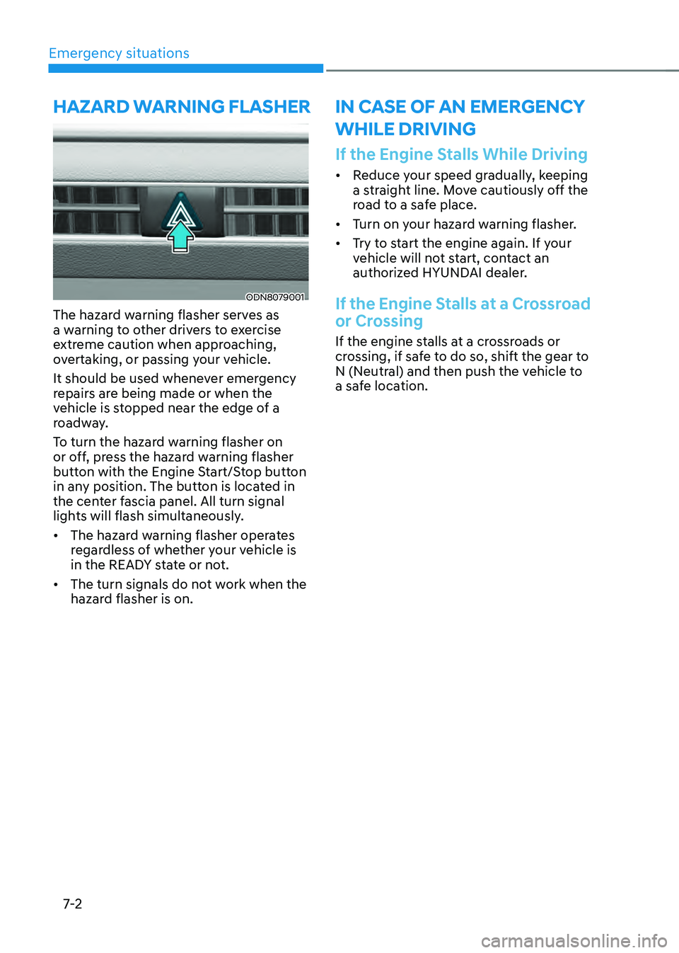
ODN8079001
The hazard warning flasher serves as
a warning to other drivers to exercise
extreme caution when approaching,
overtaking, or passing your vehicle.
It should be used whenever emergency
repairs are being made or when the
vehicle is stopped near the edge of a
roadway.
To turn the hazard warning flasher on
or off, press the hazard warning flasher
button with the Engine Start/Stop button
in any position. The button is located in
the center fascia panel. All turn signal
lights will flash simultaneously.
• The hazard warning flasher operates
regardless of whether your vehicle is
in the READY state or not.
• The turn signals do not work when the
hazard flasher is on.
If the Engine Stalls While Driving
• Reduce your speed gradually, keeping
a straight line. Move cautiously off the
road to a safe place.
• Turn on your hazard warning flasher.
• Try to start the engine again. If your
vehicle will not start, contact an
authorized HYUNDAI dealer.
If the Engine Stalls at a Crossroad
or Crossing
If the engine stalls at a crossroads or
crossing, if safe to do so, shift the gear to
N (Neutral) and then push the vehicle to
a safe location.
HAZARD WARNING FLASHER IN CASE OF AN EMERGENCY
WHILE DRIVING
Page 425 of 527
07
7-5
NOTICE
External power source using 12V battery
The use of external power accessories
may reduce performance and function
of the vehicle. Especially, the use of
dash cameras may shut off the power of
the vehicle prior to the dash camera’s
automatic shut-down.
If the power of the vehicle is shut off,
start the vehicle as explained. (refer to
“Using the 12V Battery Reset Switch”)
Jump Starting
In the event vehicle still does not have a
functional 12V battery (check if interior
lights will not turn on) then you can try
a jump start to the engine compartment
jumper terminals using a 12V booster
pack or jumper cables from another
vehicle’s 12V battery according to the
following instructions.
CAUTION
Jump starting can be dangerous if
done incorrectly. Follow the jump
starting procedure in this section to
avoid serious injury or damage to
your vehicle. If in doubt about how to
properly jump start your vehicle, we
strongly recommend that you have a
service technician or towing service do
it for you.
1. Position the vehicles close enough
that the jumper cables will reach, but
do not allow the vehicles to touch.
Avoid fans or any moving parts in the
engine compartment at all times, even
when the vehicles are turned off.
2. Turn off all electrical devices such as
radios, lights, air conditioning, etc.
Put the vehicles in P (Park) and set the
parking brake. Turn both vehicles OFF.
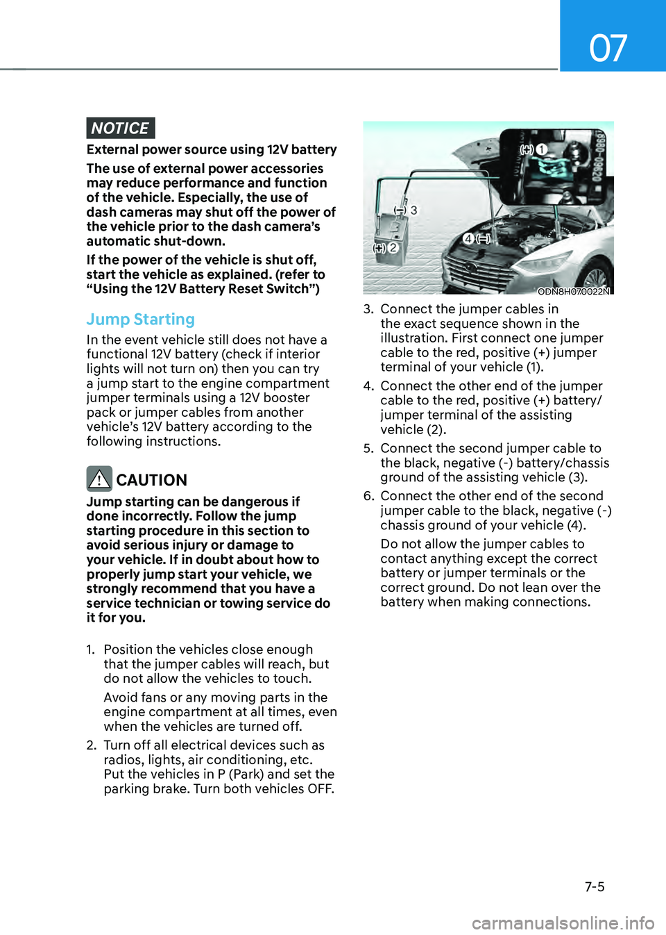
ODN8H070022N
3. Connect the jumper cables in
the exact sequence shown in the
illustration. First connect one jumper
cable to the red, positive (+) jumper
terminal of your vehicle (1).
4. Connect the other end of the jumper
cable to the red, positive (+) battery/
jumper terminal of the assisting
vehicle (2).
5. Connect the second jumper cable to
the black, negative (-) battery/chassis
ground of the assisting vehicle (3).
6. Connect the other end of the second
jumper cable to the black, negative (-)
chassis ground of your vehicle (4).
Do not allow the jumper cables to
contact anything except the correct
battery or jumper terminals or the
correct ground. Do not lean over the
battery when making connections.
Page 431 of 527
07
7-11
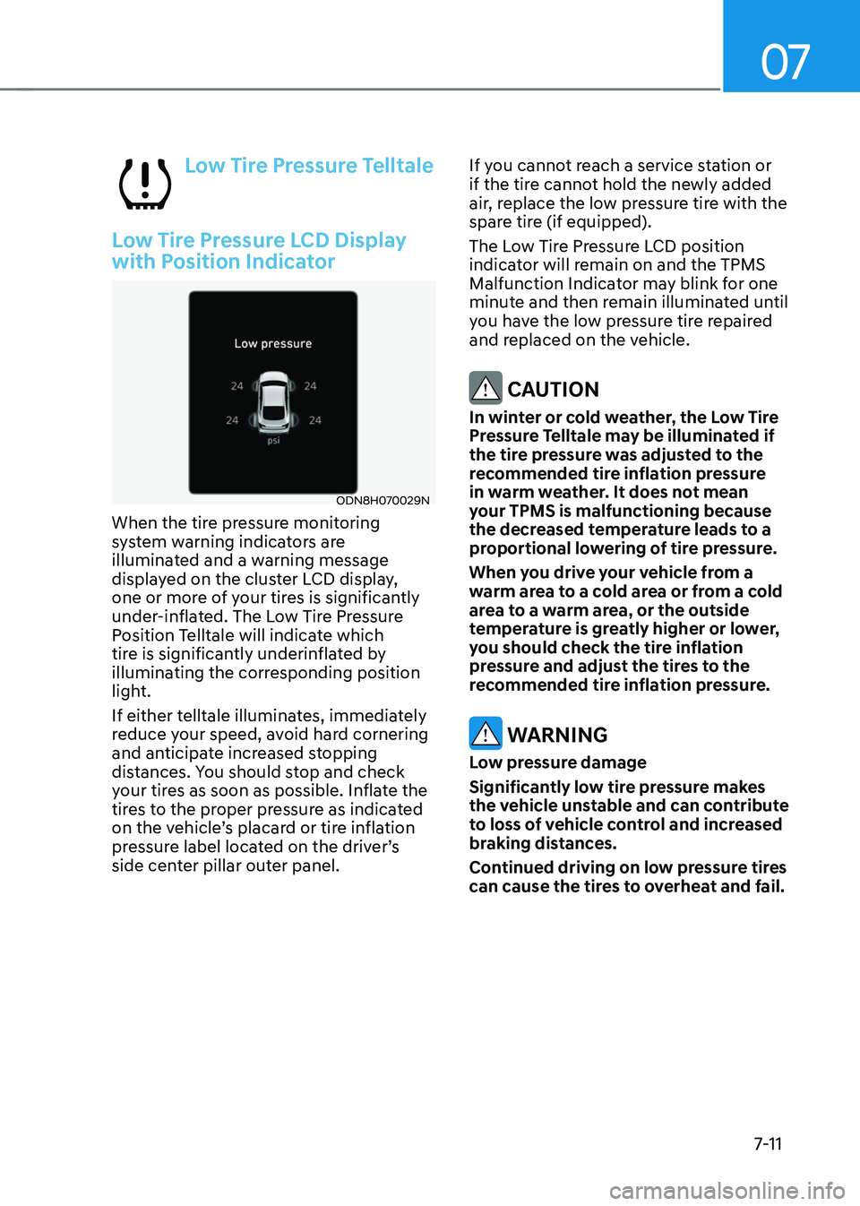
Low Tire Pressure Telltale
Low Tire Pressure LCD Display
with Position Indicator
ODN8H070029N
When the tire pressure monitoring
system warning indicators are
illuminated and a warning message
displayed on the cluster LCD display,
one or more of your tires is significantly
under-inflated. The Low Tire Pressure
Position Telltale will indicate which
tire is significantly underinflated by
illuminating the corresponding position
light.
If either telltale illuminates, immediately
reduce your speed, avoid hard cornering
and anticipate increased stopping
distances. You should stop and check
your tires as soon as possible. Inflate the
tires to the proper pressure as indicated
on the vehicle’s placard or tire inflation
pressure label located on the driver’s
side center pillar outer panel.If you cannot reach a service station or
if the tire cannot hold the newly added
air, replace the low pressure tire with the
spare tire (if equipped).
The Low Tire Pressure LCD position
indicator will remain on and the TPMS
Malfunction Indicator may blink for one
minute and then remain illuminated until
you have the low pressure tire repaired
and replaced on the vehicle.
CAUTION
In winter or cold weather, the Low Tire
Pressure Telltale may be illuminated if
the tire pressure was adjusted to the
recommended tire inflation pressure
in warm weather. It does not mean
your TPMS is malfunctioning because
the decreased temperature leads to a
proportional lowering of tire pressure.
When you drive your vehicle from a
warm area to a cold area or from a cold
area to a warm area, or the outside
temperature is greatly higher or lower,
you should check the tire inflation
pressure and adjust the tires to the
recommended tire inflation pressure.
WARNING
Low pressure damage
Significantly low tire pressure makes
the vehicle unstable and can contribute
to loss of vehicle control and increased
braking distances.
Continued driving on low pressure tires
can cause the tires to overheat and fail.
Page 433 of 527
07
7-13
You may not be able to identify a tire
with low pressure by simply looking at it.
Always use a good quality tire pressure
gauge to measure. Please note that a tire
that is hot (from being driven) will have a
higher pressure measurement than a tire
that is cold.
A cold tire means the vehicle has been
sitting for 3 hours and driven for less
than 1 mile (1.6 km) in that 3 hour period.
Allow the tire to cool before measuring
the inflation pressure. Always be sure
the tire is cold before inflating to the
recommended pressure.
WARNING
• The TPMS cannot alert you to severe
and sudden tire damage caused by
external factors such as nails or road
debris.
• If you feel any vehicle instability,
immediately take your foot off
the accelerator, apply the brakes
gradually with light force, and slowly
move to a safe position off the road.
WARNING
Tampering with, modifying, or disabling
the Tire Pressure Monitoring System
(TPMS) components may interfere
with the system’s ability to warn the
driver of low tire pressure conditions
and/or TPMS malfunctions. Tampering
with, modifying, or disabling the Tire
Pressure Monitoring System (TPMS)
components may void the warranty for
that portion of the vehicle.
WARNING
This device complies with Part 15 of the
FCC rules.
Operation is subject to the following
three conditions:
1. This device may not cause harmful
interference.
2. This device must accept any
interference received, including
interference that may cause
undesired operation.
3. Changes or modifications not
expressly approved by the party
responsible for compliance could
void the user’s authority to operate
the equipment.
Page 451 of 527
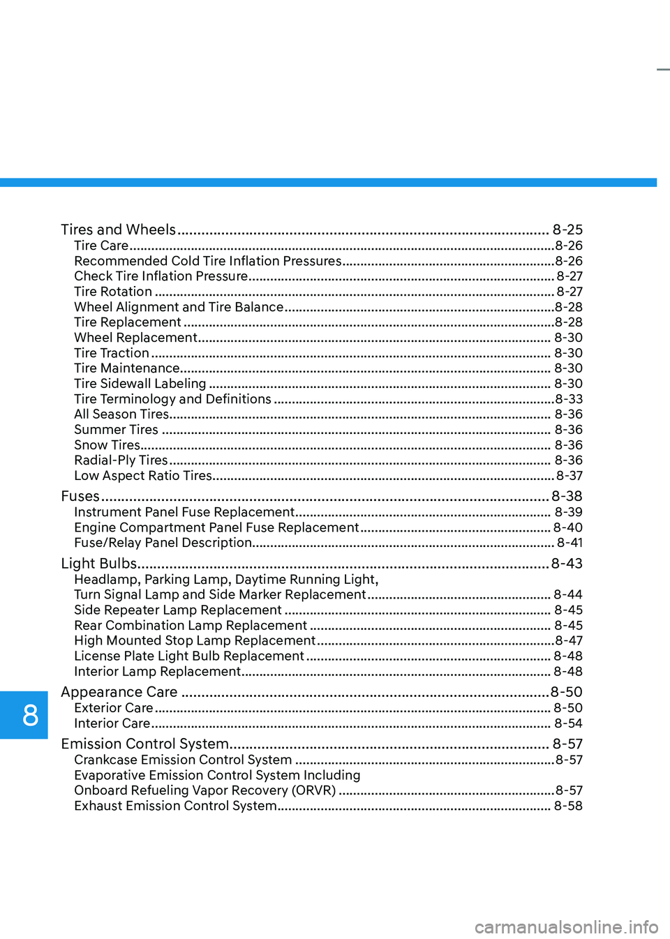
Tires and Wheels ........................................................................\
.....................8-25Tire Care ........................................................................\
..............................................8-26
Recommended Cold Tire Inflation Pressures ...........................................................8-26
Check Tire Inflation Pressure ........................................................................\
.............8-27
Tire Rotation ........................................................................\
.......................................8-27
Wheel Alignment and Tire Balance ........................................................................\
...8-28
Tire Replacement ........................................................................\
...............................8-28
Wheel Replacement ........................................................................\
..........................8-30
Tire Traction ........................................................................\
.......................................8-30
Tire Maintenance ........................................................................\
............................... 8-30
Tire Sidewall Labeling
........................................................................\
.......................8-30
Tire Terminology and Definitions ........................................................................\
......8-33
All Season Tires ........................................................................\
..................................8-36
Summer Tires ........................................................................\
....................................8-36
Snow Tires ........................................................................\
.......................................... 8-36
Radial-Ply Tires
........................................................................\
..................................8-36
Low Aspect Ratio Tires ........................................................................\
.......................8-37
Fuses ........................................................................\
........................................8-38Instrument Panel Fuse Replacement .......................................................................8-39
Engine Compartment Panel Fuse Replacement .....................................................8-40
Fuse/Relay Panel Description ........................................................................\
............ 8-41
Light Bulbs ........................................................................\
...............................8-43Headlamp, Parking Lamp, Daytime Running Light,
Turn Signal Lamp and Side Marker Replacement ...................................................8-44
Side Repeater Lamp Replacement ........................................................................\
..8-45
Rear Combination Lamp Replacement ...................................................................8-45
High Mounted Stop Lamp Replacement ..................................................................8-47
License Plate Light Bulb Replacement ....................................................................8-48
Interior Lamp Replacement ........................................................................\
..............8-48
Appearance Care ........................................................................\
....................8-50Exterior Care ........................................................................\
......................................8-50
Interior Care ........................................................................\
.......................................8-54
Emission Control System ........................................................................\
........8-57Crankcase Emission Control System ........................................................................\
8-57
Evaporative Emission Control System Including
Onboard Refueling Vapor Recovery (ORVR)
............................................................8-57
Exhaust Emission Control System ........................................................................\
....8-58
8
Page 455 of 527
Maintenance
8-6
While operating your vehicle:
• Note any changes in the sound of the
exhaust or any smell of exhaust fumes
in the vehicle.
• Check for vibrations in the steering
wheel. Notice if there is any increased
steering effort or looseness in the
steering wheel, or change in its
straight-ahead position.
• Notice if your vehicle constantly turns
slightly or “pulls” to one side when
traveling on smooth, level road.
• When stopping, listen and check for
unusual sounds, pulling to one side,
increased brake pedal travel or “hard-
to-push” brake pedal.
• If any slipping or changes in the
operation of your transmission occurs,
check the transmission fluid level.
• Check the automatic transmission P
(Park) function.
• Check the parking brake.
• Check for fluid leaks under your
vehicle (water dripping from the air
conditioning system during or after
use is normal).
At least monthly:
• Check coolant level in the engine
coolant reservoir.
• Check the operation of all exterior
lights, including the stoplights, turn
signals and hazard warning flashers.
• Check the inflation pressures of all
tires including the spare for tires that
are worn, show uneven wear, or are
damaged.
• Check for loose wheel lug nuts.
At least twice a year: (i.e., every
Spring and Autumn)
• Check radiator, heater and air
conditioning hoses for leaks or
damage.
• Check windshield washer spray and
wiper operation. Clean wiper blades
with a clean cloth dampened with
washer fluid.
• Check headlamp alignment.
• Check muffler, exhaust pipes, shields
and clamps.
• Check the seat belts for wear and
function.
At least once a year:
• Clean body and door drain holes.
• Lubricate door hinges and hood
hinges.
• Lubricate door and hood locks and
latches.
• Lubricate door rubber weather strips.
• Check the air conditioning system.
• Inspect and lubricate automatic
transmission linkage and controls.
• Clean the battery and terminals.
• Check the brake fluid level.
Page 483 of 527
Maintenance
8-34
Cold Tire Pressure
The amount of air pressure in a tire,
measured in pounds per square inch
(psi) or kilopascals (kPa) before a tire
has built up heat from driving.
Curb Weight
This means the weight of a motor
vehicle with standard and optional
equipment including the maximum
capacity of fuel, oil and coolant, but
without passengers and cargo.
DOT Markings
A code molded into the sidewall
of a tire signifying that the tire
is in compliance with the U.S.
Department of Transportation motor
vehicle safety standards. The DOT
code includes the Tire Identification
Number (TIN), an alphanumeric
designator which can also identify
the tire manufacturer, production
plant, brand and date of production.
GVWR
Gross Vehicle Weight Rating
GAWR FRT
Gross Axle Weight Rating for the
Front Axle.
GAWR RR
Gross Axle Weight Rating for the
Rear axle.
Intended Outboard Sidewall
The side of an asymmetrical tire,
that must always face outward when
mounted on a vehicle.Kilopascal (kPa)
The metric unit for air pressure.
Light truck (LT) tire
A tire designated by its manufacturer
as primarily intended for use on
lightweight trucks or multipurpose
passenger vehicles.
Load ratings
The maximum load that a tire is rated
to carry for a given inflation pressure.
Load Index
An assigned number ranging from 1
to 279 that corresponds to the load
carrying capacity of a tire.
Maximum Inflation Pressure
The maximum air pressure to which
a cold tire may be inflated. The
maximum air pressure is molded
onto the sidewall.
Maximum Load Rating
The load rating for a tire at the
maximum permissible inflation
pressure for that tire.
Maximum Loaded Vehicle Weight
The sum of curb weight; accessory
weight; vehicle capacity weight; and
production options weight.
Normal Occupant Weight
The number of occupants a vehicle
is designed to seat multiplied by 150
pounds (68 kg).
Occupant Distribution
Designated seating positions.
Page 484 of 527
08
8-35
Outward Facing Sidewall
An asymmetrical tire has a particular
side that faces outward when
mounted on a vehicle. The outward
facing sidewall bears white lettering
or bears manufacturer, brand, and/or
model name molding that is higher
or deeper than the same moldings
on the inner facing sidewall.
Passenger (P-Metric) tire
A tire used on passenger cars
and some light duty trucks and
multipurpose vehicles.
Ply
A layer of rubber-coated parallel
cords.
Pneumatic tire
A mechanical device made of rubber,
chemicals, fabric and steel or other
materials, that, when mounted on
an automotive wheel provides the
traction and contains the gas or fluid
that sustains the load.
Pneumatic options weight
The combined weight of installed
regular production options weighing
over 5 lb. (2.3 kg) in excess of the
standard items which they replace,
not previously considered in
curb weight or accessory weight,
including heavy duty breaks, ride
levelers, roof rack, heavy duty
battery, and special trim.
Recommended Inflation Pressure
Vehicle manufacturer’s
recommended tire inflation pressure
as shown on the tire placard.Radial Ply Tire
A pneumatic tire in which the ply
cords that extend to the beads are
laid at 90 degrees to the centerline
of the tread.
Rim
A metal support for a tire and upon
which the tire beads are seated.
Sidewall
The portion of a tire between the
tread and the bead.
Speed Rating
An alphanumeric code assigned to a
tire indicating the maximum speed
at which a tire can operate.
Traction
The friction between the tire and
the road surface. The amount of grip
provided.
Tread
The portion of a tire that comes into
contact with the road.
Treadwear Indicators
Narrow bands, sometimes called
“wear bars”, that show across the
tread of a tire when only 1/16 inch of
tread remains.
UTQGS
Uniform Tire Quality Grading
Standards is a tire information
system that provides consumers
with ratings for a tire’s traction,
temperature and treadwear.
Ratings are determined by tire
manufacturers using government
testing procedures. The ratings are
molded into the sidewall of the tire.
Page 486 of 527
08
8-37
Radial-ply tires have the same load
carrying capacity, as bias-ply or bias
belted tires of the same size, and use
the same recommended inflation
pressure. Mixing of radial-ply tires
with bias-ply or bias belted tires is not
recommended. Any combinations of
radial-ply and bias-ply or bias belted
tires when used on the same vehicle
will seriously deteriorate vehicle
handling. The best rule to follow
is: Identical pairs of radial-ply tires
should always be used as a set for the
front tires and a set for the rear tires.
Longer wearing tires can be more
susceptible to irregular tread wear.
It is very important to follow the tire
rotation interval in this chapter to
achieve the tread life potential of
these tires. Cuts and punctures in
radial-ply tires are repairable only in
the tread area, because of sidewall
flexing. Consult your tire dealer for
radial-ply tire repairs.
WARNING
Do not mix bias ply and radial ply
tires under any circumstances.
This may cause unusual handling
characteristics that may cause loss
of vehicle control resulting in an
accident.
Low Aspect Ratio Tires (if
equipped)
The aspect ratio is lower than 50 on low
aspect ratio tires.
Because low aspect ratio tires are
optimized for handling and braking,
their sidewall is a little stiffer than a
standard tire. Also low aspect ratio tires
tend to be wider and consequently
have a greater contact patch with
the road surface. In some instances
they may generate more road noise
compared with standard tires.
CAUTION
The side wall of a low aspect ratio
tire is shorter than the normal one.
Thus, the low-aspect wheel and
tire are easily damaged. Follow the
below instructions.
• When driving on a rough road or
driving off a road, be careful not
to damage the tires and wheels.
After driving, inspect the tires
and wheels.
• When passing over a pothole,
speed bump, manhole, or curb
stone, drive the vehicle slowly so
as not to damage the tires and
wheels.
• When there is an impact on a tire,
inspect the tire condition. Or,
contact an authorized HYUNDAI
dealer.
• Inspect the tire condition and
pressure every 1,800 miles (3,000
km) to prevent tire damage.
• It is difficult to recognize a tire
damage only with your eyes.
When there is a slight hint of a
tire damage, check and replace
the tire to prevent the damage
caused by air leakage.
• When a tire is damaged while
driving on a rough road, off a
road, or over obstacles, such as a
pothole, manhole, or curb stone,
your warranty does not cover the
damage.
• The tire information is specified
on the tire side wall.
Page 487 of 527
Maintenance
8-38
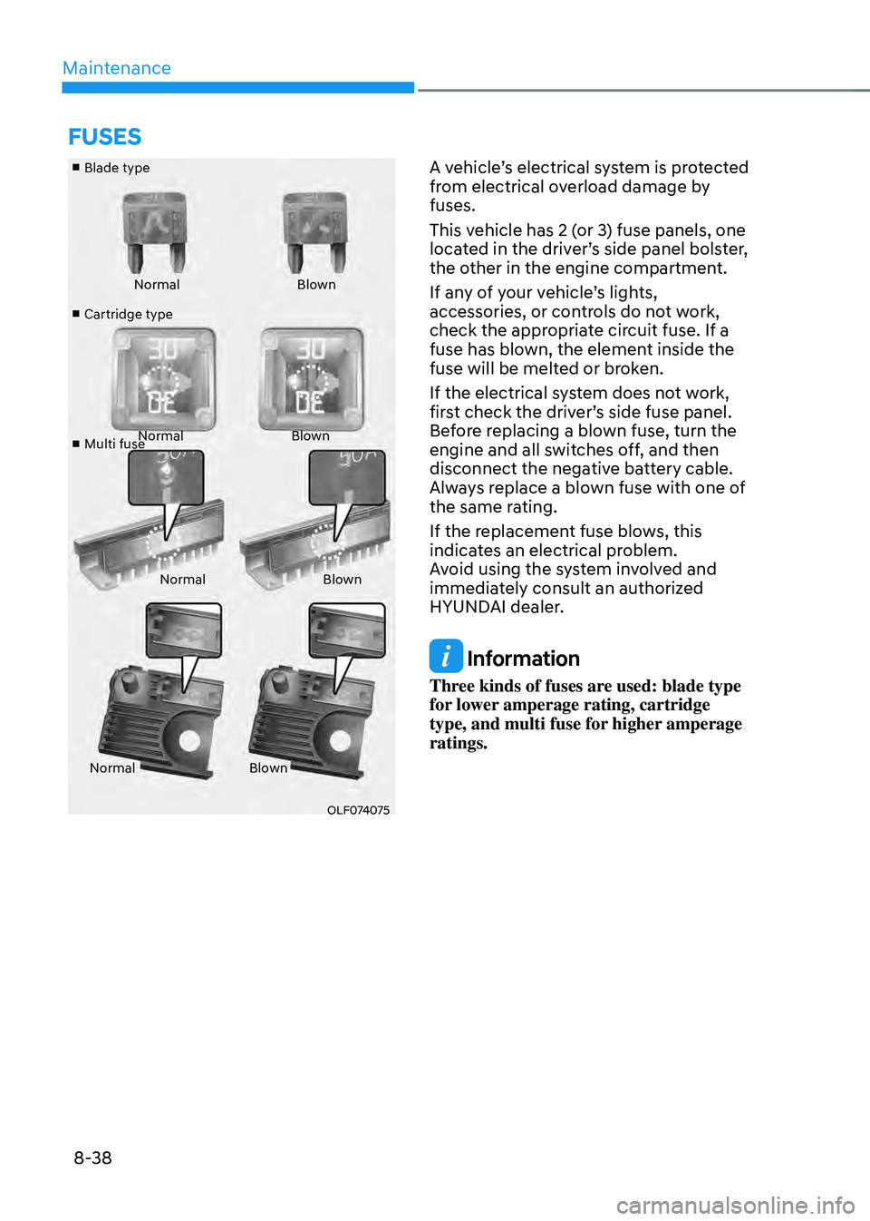
■ Blade type
■
Cartridge type
■
Multi fuse Normal
Blown
Normal Blown
Normal Blown
Normal Blown
OLF074075
A vehicle’s electrical system is protected
from electrical overload damage by
fuses.
This vehicle has 2 (or 3) fuse panels, one
located in the driver’s side panel bolster,
the other in the engine compartment.
If any of your vehicle’s lights,
accessories, or controls do not work,
check the appropriate circuit fuse. If a
fuse has blown, the element inside the
fuse will be melted or broken.
If the electrical system does not work,
first check the driver’s side fuse panel.
Before replacing a blown fuse, turn the
engine and all switches off, and then
disconnect the negative battery cable.
Always replace a blown fuse with one of
the same rating.
If the replacement fuse blows, this
indicates an electrical problem.
Avoid using the system involved and
immediately consult an authorized
HYUNDAI dealer.
Information
Three kinds of fuses are used: blade type
for lower amperage rating, cartridge
type, and multi fuse for higher amperage
ratings.
FUSES