cooling Hyundai Sonata Plug-in Hybrid 2017 User Guide
[x] Cancel search | Manufacturer: HYUNDAI, Model Year: 2017, Model line: Sonata Plug-in Hybrid, Model: Hyundai Sonata Plug-in Hybrid 2017Pages: 744, PDF Size: 27.87 MB
Page 593 of 744
7-25
7
Maintenance
Cooling system
Check cooling system components,
such as radiator, coolant reservoir,
hoses and connections for leakage
and damage. Replace any damaged
parts.
Engine coolant/Inverter
coolant
The coolant should be changed at
the intervals specified in the mainte-
nance schedule.
Automatic transmission fluid
Automatic transmission fluid should
not be checked under normal usage
conditions. But in severe conditions,
the fluid should be changed at an
authorized HYUNDAI dealer in accor-
dance to the scheduled maintenance
at the beginning of this chapter.
Automatic transmission fluid color
is basically red.
As the vehicle is driven, the auto-
matic transmission fluid will begin
to look darker. This is a normal
condition and you should not
judge the need to replace the fluid
based upon the changed color.
Brake hoses and lines
Visually check for proper installation,
chafing, cracks, deterioration and
any leakage. Replace any deteriorat-
ed or damaged parts immediately.
Brake fluid
Check brake fluid level in the brake
fluid reservoir. The level should be
between the MIN and the MAX
marks on the side of the reservoir.
Use only hydraulic brake fluid con-
forming to DOT 3 or DOT 4 specifi-
cation.
Parking brake
Inspect the parking brake system
including the parking brake pedal
and cables.
NOTICE
The use of a non-specified fluid
could result in transmission mal-
function and failure. Use only the
specified automatic transmission
fluid (refer to "Recommended
Lubricants and Capacities" in
chapter 8).
CAUTION
Page 597 of 744

7-29
7
Maintenance
E
EN
N G
GI
IN
N E
E
C
C O
O O
OL
LA
A N
N T
T/
/I
IN
N V
VE
ER
R T
TE
ER
R
C
C O
O O
OL
LA
A N
N T
T
The high-pressure cooling system
has a reservoir filled with year-round
antifreeze coolant. The reservoir is
filled at the factory.
Check the antifreeze protection and
coolant level at least once a year, at
the beginning of the winter season
and before traveling to a colder cli-
mate.Checking the engine/inverter
coolant level
OLFH074005
OLFH074006
■ Radiator cap
■Inverter coolant cap
Never remove the
radiator cap and/or
inverter coolant cap
or the drain plug
while the engine and
radiator are hot. Hot coolant
and steam may blow out under
pressure, causing serious
injury.
Turn the hybrid system off and
wait until the engine cools
down. Use extreme care when
removing the radiator cap
and/or inverter coolant cap.
Wrap a thick towel around it,
and turn it counterclockwise
slowly to the first stop. Step
back while the pressure is
released from the cooling sys-
tem. When you are sure all the
pressure has been released,
press down on the cap, using a
thick towel, and continue turn-
ing counterclockwise to remove
it.
WARNING
Page 598 of 744
7-30
Maintenance
Information
The engine coolant and/or inverter
coolant level is influenced by the
hybrid system temperature. Before
checking or refilling the engine
coolant and/or inverter coolant, turn
the hybrid vehicle off. The electric motor for the cooling fan
is controlled by engine coolant tem-
perature, refrigerant pressure and
vehicle speed. As the engine coolant
temperature decreases, the electric
motor will automatically shut off. This
is a normal condition. If your vehicle
is equipped with GDI, the electric
motor for the cooling fan may begin
to operate at any time and continue
to operate until you disconnect the
negative battery cable.
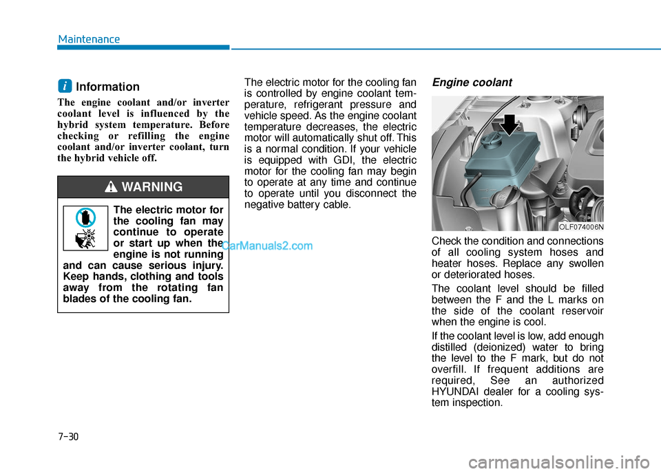
Engine coolant
Check the condition and connections
of all cooling system hoses and
heater hoses. Replace any swollen
or deteriorated hoses.
The coolant level should be filled
between the F and the L marks on
the side of the coolant reservoir
when the engine is cool.
If the coolant level is low, add enough
distilled (deionized) water to bring
the level to the F mark, but do not
overfill. If frequent additions are
required, See an authorized
HYUNDAI dealer for a cooling sys-
tem inspection.
i
The electric motor for
the cooling fan may
continue to operate
or start up when the
engine is not running
and can cause serious injury.
Keep hands, clothing and tools
away from the rotating fan
blades of the cooling fan.
WARNING
OLF074006N
Page 599 of 744
7-31
7
Maintenance
Inverter coolant
Check the condition and connections
of all cooling system hoses and
heater hoses. Replace any swollen
or deteriorated hoses.
The coolant level should be filled
between the MAX and the MIN
marks on the side of the coolant
reservoir when the engine is cool.
If the coolant level is low, add enough
distilled (deionized) water to bring
the level to the MAX mark, but do not
overfill. If frequent additions are
required, we recommend that you
see an authorized HYUNDAI dealer
for a cooling system inspection.
Recommended coolant
When adding coolant, use onlydeionized water, distilled water or
soft water for your vehicle and
never mix hard water in the coolant
filled at the factory.
An improper coolant mixture can result in severe malfunction or
engine/ hybrid system damage.
The engine in your vehicle has alu- minum engine parts and must be
protected by an phosphate-based
ethylene glycol coolant to prevent
corrosion and freezing.
Do not use alcohol or methanol coolant or mix them with the spec-
ified coolant.
Do not use a solution that contains more than 60% antifreeze or less
than 35% antifreeze, which would
reduce the effectiveness of the
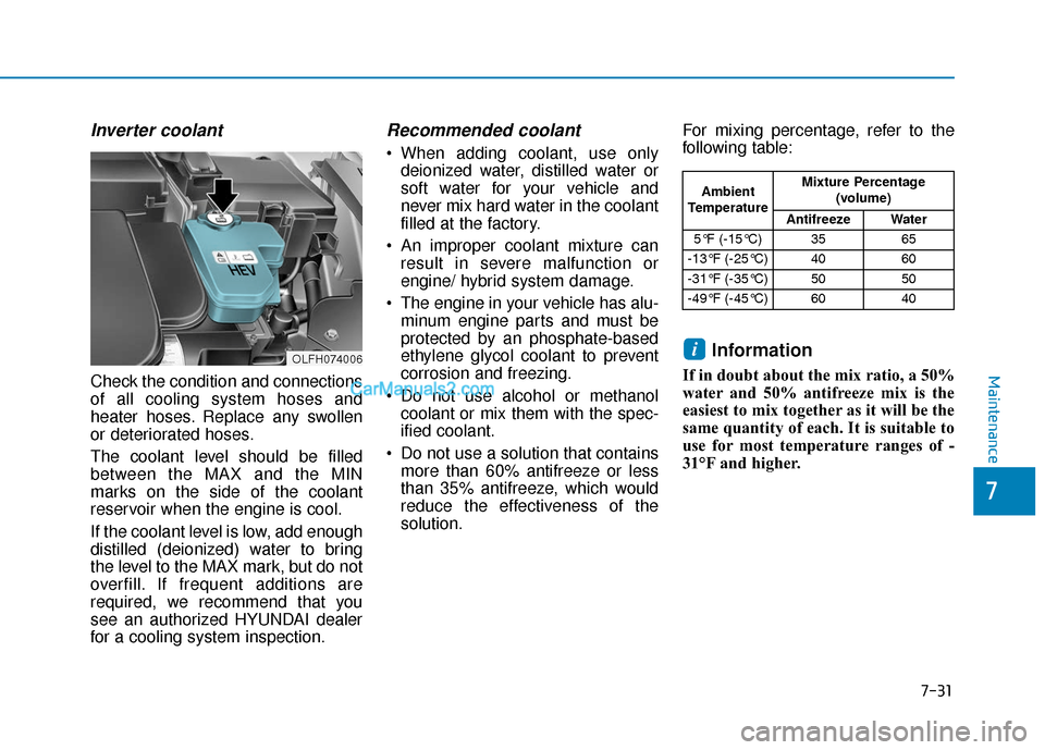
solution. For mixing percentage, refer to the
following table:
Information
If in doubt about the mix ratio, a 50%
water and 50% antifreeze mix is the
easiest to mix together as it will be the
same quantity of each. It is suitable to
use for most temperature ranges of -
31°F and higher.
i
Ambient
Temperature Mixture Percentage
(volume)
Antifreeze Water
5°F (-15°C) 35 65
-13°F (-25°C) 40 60
-31°F (-35°C) 50 50
-49°F (-45°C) 60 40
OLFH074006
Page 641 of 744
7-73
7
Maintenance
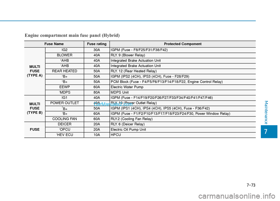
Engine compartment main fuse panel (Hybrid)
Fuse NameFuse rating Protected Component
MULTIFUSE
(TYPE A)
IG230AIGPM (Fuse - F8/F25/F31/F38/F42)
BLOWER40ARLY. 9 (Blower Relay)2AHB40AIntegrated Brake Actuation Unit1AHB40AIntegrated Brake Actuation Unit
REAR HEATED50ARLY. 12 (Rear Heated Relay)3B+50AIGPM (IPS2 (4CH), IPS3 (4CH), Fuse - F28/F29)5B+50APCM Block (Fuse - F4/F5/F6/F13/F14/F18/F22, Engine Control Relay)
EEWP60AElectric Water Pump1MDPS80AMDPS Unit
MULTI FUSE
(TYPE B)
IG140AIGPM (Fuse - F14/F19/F20/F26/F27/F33/F34/F40/F41/F47/F46)
POWER OUTLET40ARLY. 10 (Power Outlet Relay)2B+50AIGPM (IPS1 (4CH), IPS4 (4CH), IPS5 (4CH), Fuse - F36/F42)1B+60AIGPM (Fuse - F1/F2/F10/F13/F17/F18/F23/F24/F30, Power Window Relay)
COOLING FAN60ARLY.2 (Cooling Fan Relay)
FUSE
DEICER20ARLY. 6 (Deicer Relay)1OPCU20AElectric Oil Pump Unit1HEV ECU10AHPCU
Page 642 of 744
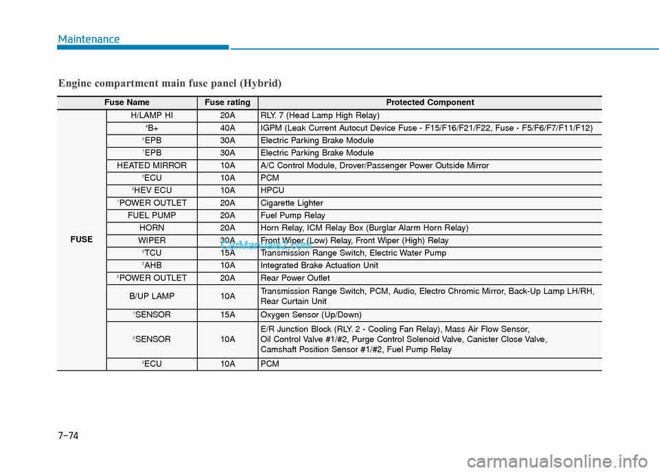
7-74
Maintenance
Fuse Name Fuse rating Protected Component
FUSE
H/LAMP HI20ARLY. 7 (Head Lamp High Relay)4B+40AIGPM (Leak Current Autocut Device Fuse - F15/F16/F21/F22, Fuse - F5/F6/F7/F11/F12)2EPB30AElectric Parking Brake Module1EPB30AElectric Parking Brake Module
HEATED MIRROR10AA/C Control Module, Drover/Passenger Power Outside Mirror3ECU10APCM2HEV ECU10AHPCU1POWER OUTLET20ACigarette Lighter
FUEL PUMP20AFuel Pump Relay
HORN20AHorn Relay, ICM Relay Box (Burglar Alarm Horn Relay)
WIPER30AFront Wiper (Low) Relay, Front Wiper (High) Relay2TCU15ATransmission Range Switch, Electric Water Pump3AHB10AIntegrated Brake Actuation Unit2POWER OUTLET20ARear Power Outlet
B/UP LAMP10ATransmission Range Switch, PCM, Audio, Electro Chromic Mirror, Back-Up Lamp LH/RH,
Rear Curtain Unit
1SENSOR15AOxygen Sensor (Up/Down)
2SENSOR10AE/R Junction Block (RLY. 2 - Cooling Fan Relay), Mass Air Flow Sensor,
Oil Control Valve #1/#2, Purge Control Solenoid Valve, Canister Close Valve,
Camshaft Position Sensor #1/#2, Fuel Pump Relay
2ECU10APCM
Engine compartment main fuse panel (Hybrid)
Page 645 of 744
7-77
7
Maintenance
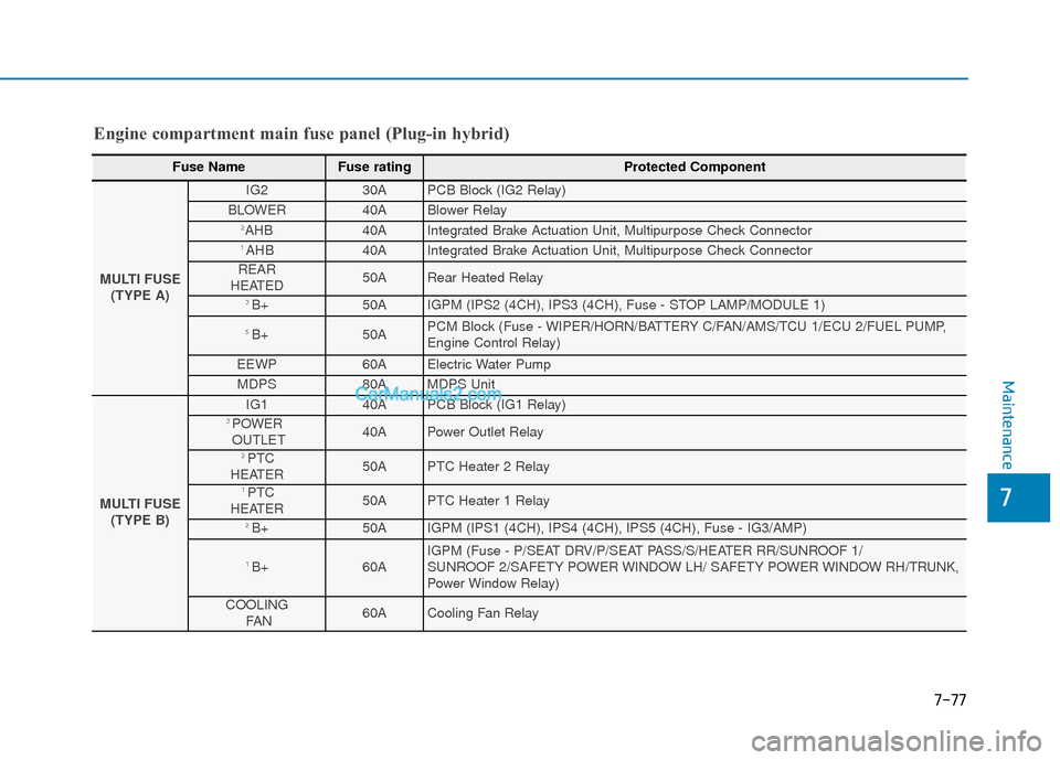
Engine compartment main fuse panel (Plug-in hybrid)
Fuse NameFuse rating Protected Component
MULTI FUSE(TYPE A)
IG2 30A PCB Block (IG2 Relay)
BLOWER 40A Blower Relay 2AHB 40A Integrated Brake Actuation Unit, Multipurpose Check Connector 1 AHB 40A Integrated Brake Actuation Unit, Multipurpose Check Connector
REAR
HEATED 50A Rear Heated Relay
3 B+ 50A IGPM (IPS2 (4CH), IPS3 (4CH), Fuse - STOP LAMP/MODULE 1)
5 B+ 50A PCM Block (Fuse - WIPER/HORN/BATTERY C/FAN/AMS/TCU 1/ECU 2/FUEL PUMP,
Engine Control Relay)
EEWP 60A Electric Water Pump
MDPS 80A MDPS Unit
MULTI FUSE (TYPE B)
IG1 40A PCB Block (IG1 Relay) 3 POWER
OUTLET 40A Power Outlet Relay
2 PTC
HEATER 50A PTC Heater 2 Relay
1 PTC
HEATER50A PTC Heater 1 Relay
2 B+ 50A IGPM (IPS1 (4CH), IPS4 (4CH), IPS5 (4CH), Fuse - IG3/AMP)
1 B+60A IGPM (Fuse - P/SEAT DRV/P/SEAT PASS/S/HEATER RR/SUNROOF 1/
SUNROOF 2/SAFETY POWER WINDOW LH/ SAFETY POWER WINDOW RH/TRUNK,
Power Window Relay)
COOLING FAN 60A Cooling Fan Relay
Page 647 of 744

7-79
7
Maintenance
Engine compartment main fuse panel (Plug-in hybrid) - PCB Block
Fuse NameFuse rating Protected Component
2 HEV
ECU10A HPCU
1 POWER
OUTLET20A Front Power Outlet
FUEL PUMP 20A Fuel Pump Relay
HORN 20A Horn Relay, ICM Relay Box (Burglar Alarm Horn Relay)
WIPER 30A Front Wiper (Low) Relay, Front Wiper (High) Relay 2 TCU15A Electric Water Pump 3 AHB10A Integrated Brake Actuation Unit 2 POWER
OUTLET20A Rear Power Outlet
B/UP LAMP 10A Transaxle Range Switch, PCM, Audio, Electro Chromic Mirror, Back-Up Lamp LH/RH 1 SENSOR 15A Oxygen Sensor (Up/Down)
2 SENSOR10A E/R Junction Block (FTIV Relay, Cooling Fan Relay), Mass Air Flow Sensor, Oil Control Valve #1/#2,
Purge Control Solenoid Valve, Fuel Pump Relay ELCM (Evaporative Leak Check Module),
Camshaft Position Sensor #1/#2
2 ECU10A PCM 1 TCU10A PCM 2 OPCU10A Electric Oil Pump Unit
BATTERY C/FAN 15A E/R Junction Block (Battery C/FAN Relay)
1 ECU20A PCM
IGN COIL 20A Ignition Coil #1/#2/#3/#4
AMS 10A Battery Sensor
Page 689 of 744
I-4
Combined instrument, see instrument cluster ................3-60
Consumer information ......................................................8-9
Coolant ........................................................................\
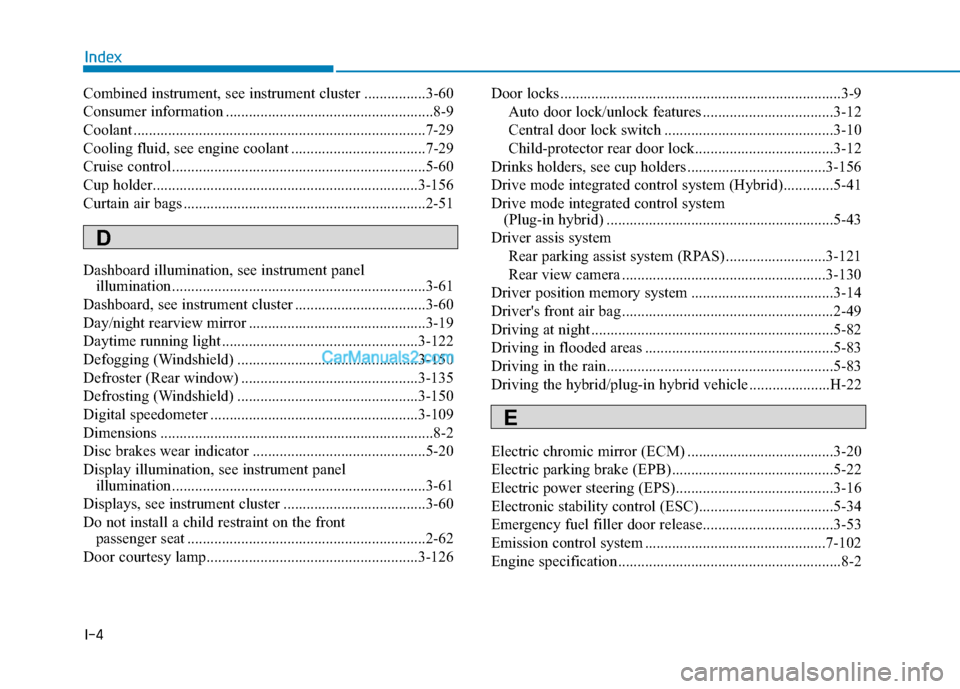
....7-29
Cooling fluid, see engine coolant ...................................7-29
Cruise control..................................................................5-60
Cup holder.....................................................................3-1\
56
Curtain air bags ...............................................................2-51
Dashboard illumination, see instrument panel illumination..................................................................3-61
Dashboard, see instrument cluster ..................................3-60
Day/night rearview mirror ..............................................3-19
Daytime running light ...................................................3-122
Defogging (Windshield) ...............................................3-150
Defroster (Rear window) ..............................................3-135
Defrosting (Windshield) ...............................................3-150
Digital speedometer ......................................................3-109
Dimensions .......................................................................8\
-2
Disc brakes wear indicator .............................................5-20
Display illumination, see instrument panel illumination..................................................................3-61
Displays, see instrument cluster .....................................3-60
Do not install a child restraint on the front passenger seat ..............................................................2-62
Door courtesy lamp.......................................................3-126 Door locks ........................................................................\
.3-9
Auto door lock/unlock features ..................................3-12
Central door lock switch ............................................3-10
Child-protector rear door lock....................................3-12
Drinks holders, see cup holders ....................................3-156
Drive mode integrated control system (Hybrid).............5-41
Drive mode integrated control system (Plug-in hybrid) ...........................................................5-43
Driver assis system Rear parking assist system (RPAS) ..........................3-121
Rear view camera .....................................................3-130
Driver position memory system .....................................3-14
Driver's front air bag .......................................................2-49
Driving at night ...............................................................5-82
Driving in flooded areas .................................................5-83
Driving in the rain...........................................................5-83
Driving the hybrid/plug-in hybrid vehicle .....................H-22
Electric chromic mirror (ECM) ......................................3-20
Electric parking brake (EPB) ..........................................5-22
Electric power steering (EPS).........................................3-16
Electronic stability control (ESC)...................................5-34
Emergency fuel filler door release..................................3-53
Emission control system ...............................................7-102
Engine specification..........................................................8-2
Index
D
E
Page 705 of 744
H8
C
CH
H A
AR
RG
G I
IN
N G
G
T
T H
H E
E
P
P L
LU
U G
G-
-I
IN
N
H
H Y
Y B
BR
RI
ID
D
V
V E
EH
H I
IC
C L
LE
E
(
( C
C O
O N
NT
T.
.)
)
• Always keep the charging connec-
tor and charging plug in clean and
dry condition. Be sure to keep the
charging cable in a condition
where there is no water or mois-
ture.
Make sure to use the designated charger for charging the vehicle.
Using any other charger may
cause failure.
Before charging the battery, turn the vehicle OFF.
Be careful not to drop the charging connector. The charging connector
can be damaged.
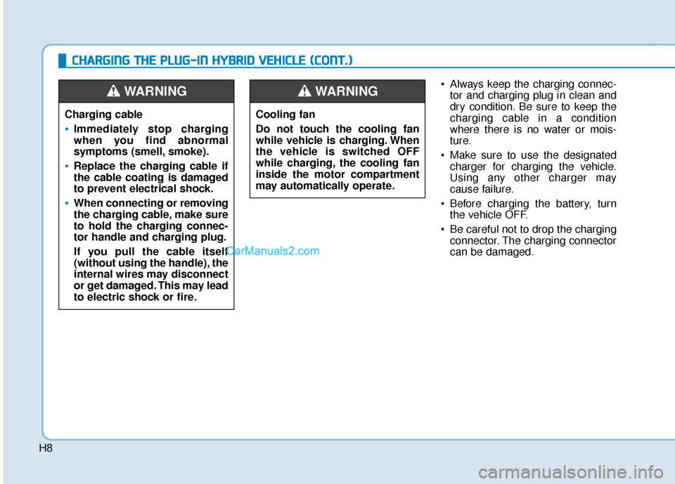
Cooling fan
Do not touch the cooling fan
while vehicle is charging. When
the vehicle is switched OFF
while charging, the cooling fan
inside the motor compartment
may automatically operate.WARNING
Charging cable
•Immediately stop charging
when you find abnormal
symptoms (smell, smoke).
Replace the charging cable if
the cable coating is damaged
to prevent electrical shock.
When connecting or removing
the charging cable, make sure
to hold the charging connec-
tor handle and charging plug.
If you pull the cable itself
(without using the handle), the
internal wires may disconnect
or get damaged. This may lead
to electric shock or fire.
WARNING