ECO mode Hyundai Sonata Plug-in Hybrid 2017 Owner's Manual
[x] Cancel search | Manufacturer: HYUNDAI, Model Year: 2017, Model line: Sonata Plug-in Hybrid, Model: Hyundai Sonata Plug-in Hybrid 2017Pages: 744, PDF Size: 27.87 MB
Page 63 of 744
2-46
Safety system of your vehicle
5. Remove as much slack from the belt as possible by pushing down
on the child restraint system while
feeding the shoulder belt back into
the retractor.
6. Push and pull on the child restraint system to confirm that the seat
belt is holding it firmly in place. If it
is not, release the seat belt and
repeat steps 2 through 6.
7. Double check that the retractor is in the "Automatic Locking" mode
by attempting to pull more of the
seat belt out of the retractor. If you
cannot, the retractor is in the
"Automatic Locking" mode.
If your CRS manufacturer instructs or
recommends you to use a tether
anchor with the lap/shoulder belt,
refer to the previous pages for more
information. When the seat belt is allowed to
retract to its fully stowed position,
the retractor will automatically
switch from the "Automatic
Locking" mode to the emergency
lock mode for normal adult usage.
To remove the child restraint, press
the release button on the buckle and
then pull the lap/shoulder belt out of
the restraint and allow the seat belt
to retract fully.
NOTICE
If the retractor is not in the
"Automatic Locking" mode, the
child restraint can move when
your vehicle turns or stops sud-
denly. A child can be seriously
injured or killed if the child
restraint is not properly anchored
in the car, including manually
pulling the seat belt all the way
out to shift the rectractor to the
"Automatic Locking" mode.
WARNING
Page 66 of 744
2-49
Safety system of your vehicle
2
Where Are the Air Bags?
Driver's and passenger's frontair bags
Your vehicle is equipped with a
Advanced Supplemental Restraint
System (SRS) and lap/shoulder belts
at both the driver and passenger
seating positions.
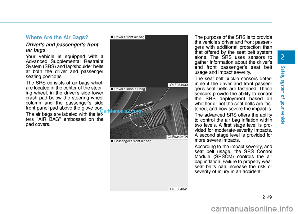
The SRS consists of air bags which
are located in the center of the steer-
ing wheel, in the driver’s side lower
crash pad below the steering wheel
column and the passenger’s side
front panel pad above the glove box.
The air bags are labeled with the let-
ters "AIR BAG" embossed on the
pad covers. The purpose of the SRS is to provide
the vehicle’s driver and front passen-
gers with additional protection than
that offered by the seat belt system
alone. The SRS uses sensors to
gather information about the driver’s
and front passenger’s seat belt
usage and impact severity.
The seat belt buckle sensors deter-
mine if the driver and front passen-
ger’s seat belts are fastened. These
sensors provide the ability to control
the SRS deployment based on
whether or not the seat belts are fas-
tened, and how severe the impact is.
The advanced SRS offers the ability
to control the air bag inflation within
two levels. A first stage level is pro-
vided for moderate-severity impacts.
A second stage level is provided for
more severe impacts.
According to the impact severity, and
seat belt usage, the SRS Control
Module (SRSCM) controls the air
bag inflation. Failure to properly wear
seat belts can increase the risk or
severity of injury in an accident.
OLF034039
OLF034040N
OLF034041
■Driver’s knee air bag
■Driver’s front air bag
■Passenger’s front air bag
Page 92 of 744
3-5
Convenient features of your vehicle
3
Panic button
Press the Panic button (4) and hold
for more than one second. The horn
sounds and hazard warning lights
blink for about 30 seconds. To cancel
the panic mode, press any button on
the Smart Key.
Start-up
You can start the engine without
inserting the key.
For more information, refer to the
"Engine Start/Stop Button" sec-
tion in chapter 5.
To prevent damaging the smart key:
• Keep the smart key in a cool, dryplace to avoid damage or mal-
function. Exposure to moisture
or high temperature may cause
the internal circuit of the smart
key to malfunction which may
not be covered under warranty.
Avoid dropping or throwing the smart key.
Protect the smart key from extreme temperatures. Always have the smart key with
you when leaving the vehicle. If
the smart key is left near the vehi-
cle, the vehicle battery may be dis-
charged.
Mechanical key
If the Smart Key does not operate
normally, you can lock or unlock the
door by using the mechanical key.
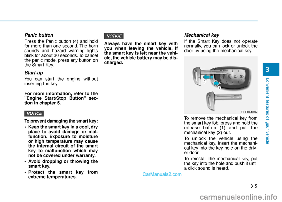
To remove the mechanical key from
the smart key fob, press and hold the
release button (1) and pull the
mechanical key (2) out.
To unlock the vehicle using the
mechanical key, insert the mechani-
cal key into the key hole on the driv-
er door.
To reinstall the mechanical key, put
the key into the hole and push it until
a click sound is heard.
NOTICE
NOTICEOLF044007
Page 111 of 744
3-24
Convenient features of your vehicle
Programming HomeLink®
Please note the following:
When programming a garage dooropener, it is advised to park the
vehicle outside of the garage.
It is recommended that a new bat- tery be placed in the hand-held
transmitter of the device being pro-
grammed to HomeLink
®for quicker
training and accurate transmission
of the radio-frequency signal.
Some vehicles may require the engine Start/Stop button to be
placed in the ACC position for pro-
gramming and/or operation of
HomeLink
®.
In the event that there are still pro- gramming difficulties or questions
after following the programming
steps listed below, contact
HomeLink
®at: www.homelink.com
or by calling 1-800-355-3515.
Programming
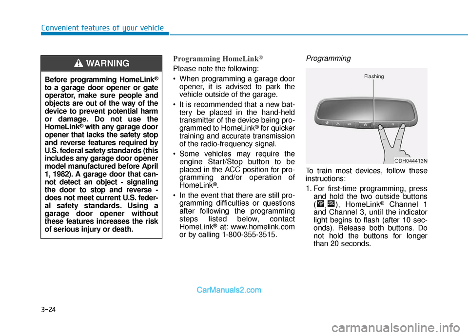
To train most devices, follow these
instructions:
1. For first-time programming, press and hold the two outside buttons
( ,), HomeLink
®Channel 1
and Channel 3, until the indicator
light begins to flash (after 10 sec-
onds). Release both buttons. Do
not hold the buttons for longer
than 20 seconds.
ODH044413N
Flashing
Before programming HomeLink®
to a garage door opener or gate
operator, make sure people and
objects are out of the way of the
device to prevent potential harm
or damage. Do not use the
HomeLink
®with any garage door
opener that lacks the safety stop
and reverse features required by
U.S. federal safety standards (this
includes any garage door opener
model manufactured before April
1, 1982). A garage door that can-
not detect an object - signaling
the door to stop and reverse -
does not meet current U.S. feder-
al safety standards. Using a
garage door opener without
these features increases the risk
of serious injury or death.
WARNING
Page 114 of 744
3-27
Convenient features of your vehicle
3
Erasing HomeLink®buttons
Individual buttons cannot be erased.
However, to erase all three pro-
grammed buttons:
1. Press and hold the two outerHomeLink
®buttons until the indi-
cator light begins to flash after 10
seconds.
2. Release both buttons. Do not hold for longer than 20 seconds.
The Integrated HomeLink
®Wireless
Control System is now in the training
(learn) mode and can be pro-
grammed at any time following the
appropriate steps in the
Programming chapters above.
NVS
®is a registered trademark and
Z-Nav™ is a trademark of the Gentex
Corporation, Zeeland, Michigan.
HomeLink
®is a registered trademark
owned by Johnson Controls,
Incorporated, Milwaukee, Wisconsin.
FCC ID: NZLTLMHL4
IC: 4112A-TLMHL4
Information
This device complies with Part 15 of
the FCC Rules.
Operation is subject to the following
three conditions:
1. This device may not cause harmful interference.
2. This device must accept any inter- ference received, including interfer-
ence that may cause undesired
operation.
3. The transceiver has been tested and complies with FCC and Industry
Canada rules. Changes or modifica-
tions not expressly approved by the
party responsible for compliance
could void the user’s authority to
operate the device.
Electric chromic mirror (ECM)with compass and HomeLink®
system (for Canada)
Your vehicle may be equipped with a
Gentex Automatic-Dimming Mirror
with a Z-Nav™ Electronic Compass
Display and an Integrated HomeLink
®
Wireless Control System.
During nighttime driving, this feature
will automatically detect and reduce
rearview mirror glare while the com-
pass indicates the direction the vehi-
cle is pointed. The HomeLink
®
Universal Transceiver allows you to
activate your garage door(s), electric
gate, home lighting, etc.
i
Page 118 of 744
3-31
Convenient features of your vehicle
3
Programming HomeLink®
Please note the following:
When programming a garage dooropener, it is advised to park the
vehicle outside of the garage.
It is recommended that a new bat- tery be placed in the hand-held
transmitter of the device being pro-
grammed to HomeLink
®for quicker
training and accurate transmission
of the radio-frequency signal.
Some vehicles may require the engine Start/Stop button to be
placed in the ACC position for pro-
gramming and/or operation of
HomeLink
®.
In the event that there are still pro- gramming difficulties or questions
after following the programming
steps listed below, contact
HomeLink
®at: www.homelink.com
or by calling 1-800-355-3515.
Rolling code programming
Rolling code devices which are
"code-protected" and manufactured
after 1996 may be determined by the
following:
Reference the device owner’s manual for verification.
The handheld transmitter appears to program the HomeLink
®
Universal Transceiver but does not
activate the device.
Press and hold the trained HomeLink button. The device has
the rolling code feature if the indi-
cator light flashes rapidly and then
turns solid after 2 seconds.
Before programming HomeLink
®
to a garage door opener or gate
operator, make sure people and
objects are out of the way of the
device to prevent potential harm
or damage. Do not use the
HomeLink
®with any garage door
opener that lacks the safety stop
and reverse features required by
U.S. federal safety standards (this
includes any garage door opener
model manufactured before April
1, 1982). A garage door that can-
not detect an object - signaling
the door to stop and reverse -
does not meet current U.S. feder-
al safety standards. Using a
garage door opener without
these features increases the risk
of serious injury or death.
WARNING
Page 121 of 744
3-34
Convenient features of your vehicle
Erasing HomeLink®buttons
Individual buttons cannot be erased.
However, to erase all three pro-
grammed buttons:
1. Press and hold the two outerHomeLink
®buttons until the indi-
cator light begins to flash-after 20
seconds.
2. Release both buttons. Do not hold for longer than 30 seconds.
The Integrated HomeLink
®Wireless
Control System is now in the training
(learn) mode and can be pro-
grammed at any time following the
appropriate steps in the Programming
chapters above.
NVS
®is a registered trademark and
Z-Nav™ is a trademark of the Gentex
Corporation, Zeeland, Michigan.
HomeLink
®is a registered trademark
owned by Johnson Controls,
Incorporated, Milwaukee, Wisconsin.
FCC ID: NZLZTVHL3
IC: 4112A-ZTVHL3
Information
This device complies with Part 15 of
the FCC Rules.
Operation is subject to the following
three conditions:
1. This device may not cause harmful interference, and
2. This device must accept any interfer- ence received, including interference
that may cause undesired operation.
3. The transceiver has been tested and complies with FCC and Industry
Canada rules. Changes or modifica-
tions not expressly approved by the
party responsible for compliance
could void the user’s authority to
operate the device.
Side View Mirrors
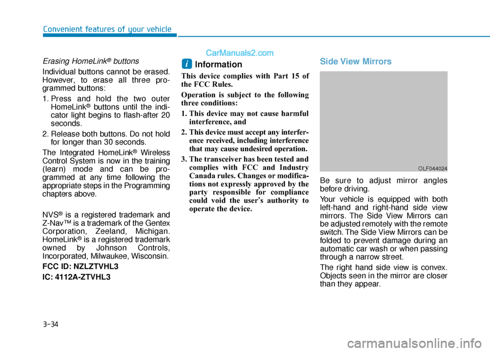
Be sure to adjust mirror angles
before driving.
Your vehicle is equipped with both
left-hand and right-hand side view
mirrors. The Side View Mirrors can
be adjusted remotely with the remote
switch. The Side View Mirrors can be
folded to prevent damage during an
automatic car wash or when passing
through a narrow street.
The right hand side view is convex.
Objects seen in the mirror are closer
than they appear.
i
OLF044024
Page 150 of 744
Convenient features of your vehicle
3
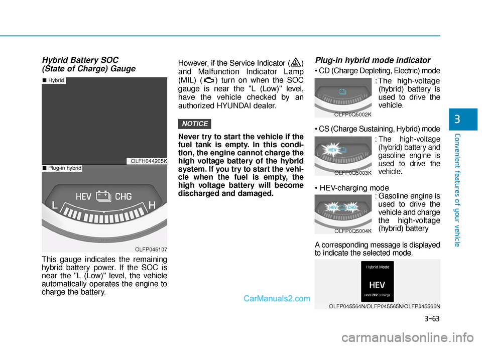
Hybrid Battery SOC (State of Charge) Gauge
This gauge indicates the remaining
hybrid battery power. If the SOC is
near the "L (Low)" level, the vehicle
automatically operates the engine to
charge the battery. However, if the Service Indicator ( )
and Malfunction Indicator Lamp
(MIL) ( ) turn on when the SOC
gauge is near the "L (Low)" level,
have the vehicle checked by an
authorized HYUNDAI dealer.
Never try to start the vehicle if the
fuel tank is empty. In this condi-
tion, the engine cannot charge the
high voltage battery of the hybrid
system. If you try to start the vehi-
cle when the fuel is empty, the
high voltage battery will become
discharged and damaged.
Plug-in hybrid mode indicator
: The high-voltage(hybrid) battery is
used to drive the
vehicle.
:The high-voltage
(hybrid) battery and
gasoline engine is
used to drive the
vehicle.
: Gasoline engine isused to drive the
vehicle and charge
the high-voltage
(hybrid) battery
A corresponding message is displayed
to indicate the selected mode.
NOTICE
OLFH044205K
OLFP045107
■ Plug-in hybrid
■Hybrid
OLFP0Q5002K
OLFP0Q5003K
OLFP0Q5004K
OLFP045564N/OLFP045565N/OLFP045566N
3-63
Page 153 of 744
3-66
Convenient features of your vehicle
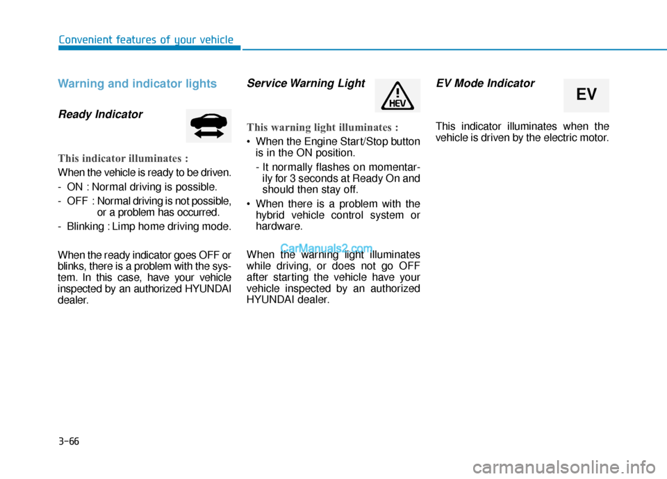
Warning and indicator lights
Ready Indicator
This indicator illuminates :
When the vehicle is ready to be driven.
- ON : Normal driving is possible.
- OFF : Normal driving is not possible,
or a problem has occurred.
- Blinking : Limp home driving mode.
When the ready indicator goes OFF or
blinks, there is a problem with the sys-
tem. In this case, have your vehicle
inspected by an authorized HYUNDAI
dealer.
Service Warning Light
This warning light illuminates :
When the Engine Start/Stop button is in the ON position.
- It normally flashes on momentar-ily for 3 seconds at Ready On and
should then stay off.
When there is a problem with the hybrid vehicle control system or
hardware.
When the warning light illuminates
while driving, or does not go OFF
after starting the vehicle have your
vehicle inspected by an authorized
HYUNDAI dealer.
EV Mode Indicator
This indicator illuminates when the
vehicle is driven by the electric motor.
EV
Page 162 of 744
3-75
Convenient features of your vehicle
3
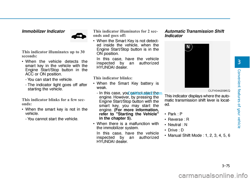
Immobilizer Indicator
This indicator illuminates up to 30
seconds:
When the vehicle detects thesmart key in the vehicle with the
Engine Start/Stop button in the
ACC or ON position.
- You can start the vehicle.
- The indicator light goes off afterstarting the vehicle.
This indicator blinks for a few sec-
onds:
When the smart key is not in the vehicle.
- You cannot start the vehicle.
This indicator illuminates for 2 sec-
onds and goes off:
When the Smart Key is not detect-ed inside the vehicle, when the
Engine Start/Stop button is in the
ON position.
In this case, have the vehicle
inspected by an authorized
HYUNDAI dealer.
This indicator blinks:
When the Smart Key battery isweak.
- In this case, you cannot start theengine. However, by pressing the
Engine Start/Stop button with the
smart key, you may start the
engine. (For more information,
refer to "Starting the Vehicle"
in the chapter 5).
When there is a malfunction with the immobilizer system.
In this case, have the vehicle
inspected by an authorized
HYUNDAI dealer.
Automatic Transmission ShiftIndicator
This indicator displays where the auto-
matic transmission shift lever is locat-
ed.
Reverse : R
Neutral : N
Manual Shift Mode : 1, 2, 3, 4, 5, 6
OLFH044209K/Q