instrument panel Hyundai Terracan 2005 User Guide
[x] Cancel search | Manufacturer: HYUNDAI, Model Year: 2005, Model line: Terracan, Model: Hyundai Terracan 2005Pages: 539, PDF Size: 18.03 MB
Page 269 of 539
6
DO-IT-YOURSELF MAINTENANCE
47
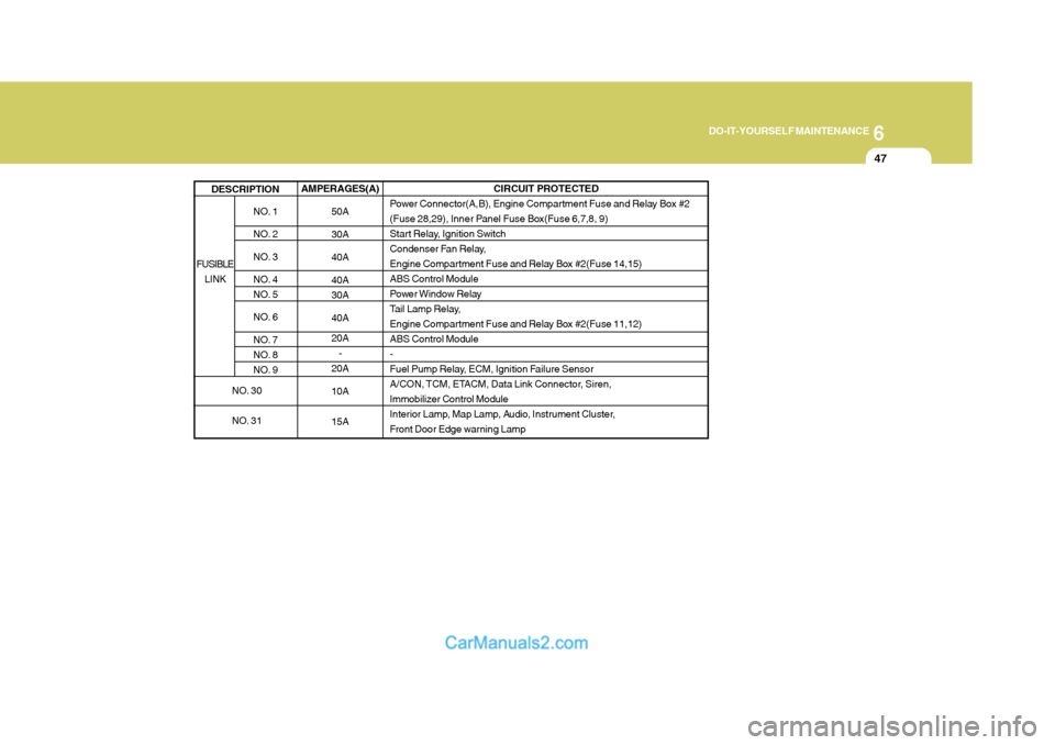
AMPERAGES(A) 50A 30A 40A 40A 30A 40A 20A-
20A 10A 15A
NO. 1
NO. 2
NO. 3
NO. 4
NO. 5
NO. 6
NO. 7
NO. 8
NO. 9
DESCRIPTION
CIRCUIT PROTECTED
Power Connector(A,B), Engine Compartment Fuse and Relay Box #2
(Fuse 28,29), Inner Panel Fuse Box(Fuse 6,7,8, 9)
Start Relay, Ignition Switch
Condenser Fan Relay,
Engine Compartment Fuse and Relay Box #2(Fuse 14,15)ABS Control Module
Power Window Relay
Tail Lamp Relay,
Engine Compartment Fuse and Relay Box #2(Fuse 11,12)ABS Control Module-
Fuel Pump Relay, ECM, Ignition Failure Sensor
A/CON, TCM, ETACM, Data Link Connector, Siren,
Immobilizer Control Module
Interior Lamp, Map Lamp, Audio, Instrument Cluster,
Front Door Edge warning Lamp
FUSIBLE LINK
NO. 30
NO. 31
Page 270 of 539
6 DO-IT-YOURSELF MAINTENANCE
48
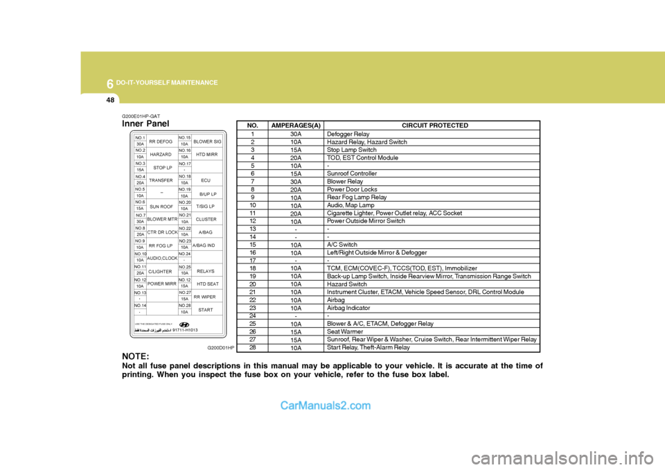
NO.1 2 34 5 67 8 9
10 11 1213 14 1516 17 1819 20 2122 23 2425 26 2728 AMPERAGES(A)
30A 10A 15A 20A10A15A30A20A 10A 10A20A10A- -
10A 10A -
10A10A10A10A 10A 10A
-
10A15A15A 10A CIRCUIT PROTECTED
Defogger Relay
Hazard Relay, Hazard Switch Stop Lamp Switch
TOD, EST Control Module - Sunroof Controller
Blower Relay
Power Door Locks
Rear Fog Lamp Relay
Audio, Map Lamp
Cigarette Lighter, Power Outlet relay, ACC Socket
Power Outside Mirror Switch- - A/C Switch
Left/Right Outside Mirror & Defogger -
TCM, ECM(COVEC-F), TCCS(TOD, EST), Immobilizer
Back-up Lamp Switch, Inside Rearview Mirror, Transmission Range Switch Hazard Switch
Instrument Cluster, ETACM, Vehicle Speed Sensor, DRL Control ModuleAirbag Airbag Indicator -
Blower & A/C, ETACM, Defogger Relay
Seat Warmer
Sunroof, Rear Wiper & Washer, Cruise Switch, Rear Intermittent Wiper Relay
Start Relay, Theft-Alarm Relay
G200E01HP-GAT Inner Panel NOTE: Not all fuse panel descriptions in this manual may be applicable to your vehicle. It is accurate at the time of printing. When you inspect the fuse box on your vehicle, refer to the fuse box label. G200D01HP
Page 291 of 539
10INDEX
4
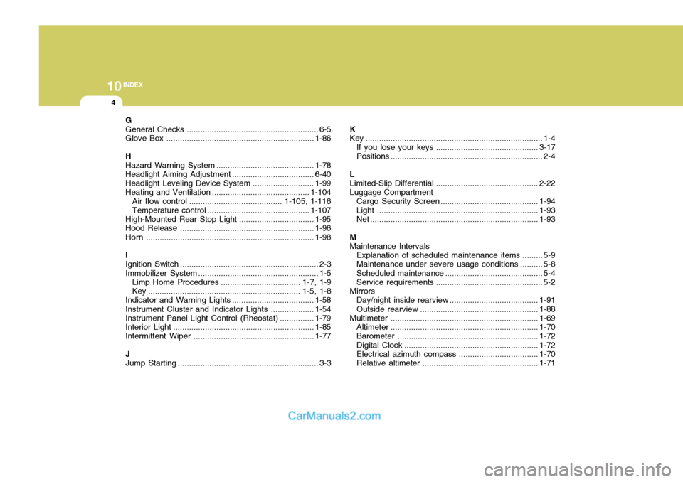
G General Checks .......................................................... 6-5
Glove Box ................................................................. 1-86
HHazard Warning Syst em ........................................... 1-78
Headlight Aiming Adjustment ....................................6-40
Headlight Leveling Device Syst em ...........................1-99
Heating and Ventilation ................. ......................... . 1-104
Air flow control ......................................... 1-105, 1-116 Temperature control ............................................. 1-107
High-Mounted Rear Stop Light ................................. 1-95
Hood Release ........................................................... 1-96
Horn .......................................................................... 1-98
IIgnition Sw itch ............................................................. 2-3
Immobilizer S ystem ..................................................... 1-5
Limp Home Procedures ................................... 1-7, 1-9
Key ................................................................... 1-5, 1-8
Indicator and Warning Lights.................................... 1-58
Instrument Cluster and Indicator Li ghts................... 1-54
Instrument Panel Light Control (Rheo stat)............... 1-79
Interior Light .............................................................. 1-85
Intermittent Wiper ..................................................... 1-77
J Jump Starting .............................................................. 3-3 K
Key .............................................................................. 1-4
If you lose your keys ............................................. 3-17
Positions ................................................................... 2-4
L Limited-Slip D ifferential ............................................. 2-22
Luggage Compartment
Cargo Security Scr een ........................................... 1-94
Light ....................................................................... 1-93
Net .......................................................................... 1-93
M Maintenance Intervals Explanation of scheduled maintenance items ......... 5-9
Maintenance under severe usage conditions .......... 5-8 Scheduled maintenance ........................................... 5-4
Service requ irements............................................... 5-2
Mirrors Day/night inside rearview .......................................1-91
Outside rearview .................................................... 1-88
Multimet er ................................................................. 1-69
Altimeter ................................................................. 1-70
Barometer .............................................................. 1-72
Digital Clock ........................................................... 1-72
Electrical azi muth compass ................................... 1-70
Relative altimeter ................................................... 1-71
Page 304 of 539
CAUTION:
When installing a container of liquid air freshener inside the vehicle, do not place it near the instrument cluster nor on the instrument panel pad surface. If there is any leakage from theair freshener onto these areas (Instrument cluster, instrument panel pad or air ventilator), it may damage these parts. If the liquid from air freshener does leak onto these areas, wash them with water immediately.!
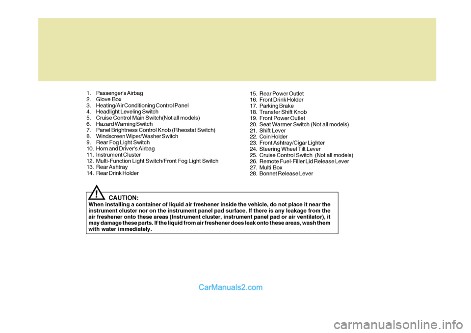
1. Passenger's Airbag
2. Glove Box
3. Heating/Air Conditioning Control Panel
4. Headlight Leveling Switch
5. Cruise Control Main Switch(Not all models)
6. Hazard Warning Switch
7. Panel Brightness Control Knob (Rheostat Switch)
8. Windscreen Wiper/Washer Switch
9. Rear Fog Light Switch
10. Horn and Driver's Airbag
11. Instrument Cluster
12. Multi-Function Light Switch/Front Fog Light Switch
13. Rear Ashtray
14. Rear Drink Holder
15. Rear Power Outlet
16. Front Drink Holder
17. Parking Brake
18. Transfer Shift Knob
19. Front Power Outlet
20. Seat Warmer Switch (Not all models)
21. Shift Lever
22. Coin Holder
23. Front Ashtray/Cigar Lighter
24. Steering Wheel Tilt Lever
25. Cruise Control Switch (Not all models)
26. Remote Fuel-Filler Lid Release Lever
27. Multi Box
28. Bonnet Release Lever
Page 324 of 539
1
CONTROLS AND EQUIPMENT
19
!
!
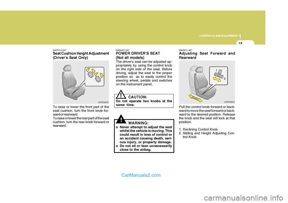
B080F01S-EAT Seat Cushion Height Adjustment (Driver's Seat Only) To raise or lower the front part of the seat cushion, turn the front knob for- ward or rearward. To raise or lower the rear part of the seatcushion, turn the rear knob forward or rearward. B090A02Y-EAT POWER DRIVER'S SEAT (Not all models) The driver's seat can be adjusted ap- propriately by using the control knob on the right side of the seat. Beforedriving, adjust the seat to the proper position so as to easily control the steering wheel, pedals and switcheson the instrument panel.
CAUTION:
Do not operate two knobs at thesame time.
WARNING:
o Never attempt to adjust the seat whilst the vehicle is moving. Thiscould result in loss of control oran accident causing death, seri- ous injury, or property damage.
o Do not sit or lean unnecessarily close to the airbag.
HHP2028-E B090B01L-AAT Adjusting Seat Forward and Rearward Pull the control knob forward or back- ward to move the seat forward or back- ward to the desired position. Release the knob and the seat will lock at thatposition.
1. Reclining Control Knob
2. Sliding and Height Adjusting Con-
trol KnobHHP2029-E
2
1
Page 344 of 539
1
CONTROLS AND EQUIPMENT
39
NOTE:
o Both the driver's and front passenger's pre-tensioner seat belts will be activated in certainfrontal collisions. The pre- tensioner seat belts can be acti- vated alone or, where the frontalcollision is severe enough, to- gether with the airbags.
o When the pre-tensioner seat belts are activated, a loud noise may beheard and fine dust, which may appear to be smoke, may be vis-ible in the passenger compart- ment. These are normal operating conditions and are not hazard-ous.
o Although it is harmless, the fine
dust may cause skin irritation andshould not be breathed for pro- longed periods. Wash your hands and face thoroughly after an acci-dent in which the pre-tensioner seat belts were activated.
!!CAUTION:
o Because the sensor that activates the SRS airbag is connected with pre-tensioner seat belt, the SRS airbag warning light on theinstrument panel will blink for ap- proximately 6 seconds after the ignition key has been turned to the"ON" position or after the engine is started, and then it should turn off.
o If pre-tensioner seat belt is not working properly, this warninglight will illuminate even if there isno malfunction of the SRS airbag. If the SRS airbag warning light does not blink for about 6 secondswhen the ignition key is turned to "ON" or the engine is started, or if it remains illuminated after blink-ing for approximately 6 seconds, or if it illuminates whilst the ve- hicle is being driven, please havean authorised Hyundai dealer in- spect the pre-tensioner seat belts and SRS airbag system as soon aspossible. WARNING:
o Pre-tensioners are designed to operate only one time. After acti- vation, pre-tensioner seat belts must be replaced. All seat belts,of any type, should always be replaced after they have been worn during a collision.
o The pre-tensioner seat belt as- sembly mechanisms become hotduring activation. Do not touchthe pre-tensioner seat belt as- semblies for several minutes af- ter they have been activated.
o Do not attempt to inspect or re-
place the pre-tensioner seat beltsyourself. This must be done by an authorised Hyundai dealer.
o Do not strike the pre-tensioner seat belt assemblies.
o Do not attempt to service or re-
pair the pre-tensioner seat belt system in any manner.
AIR
BAG
Page 347 of 539
1CONTROLS AND EQUIPMENT
42
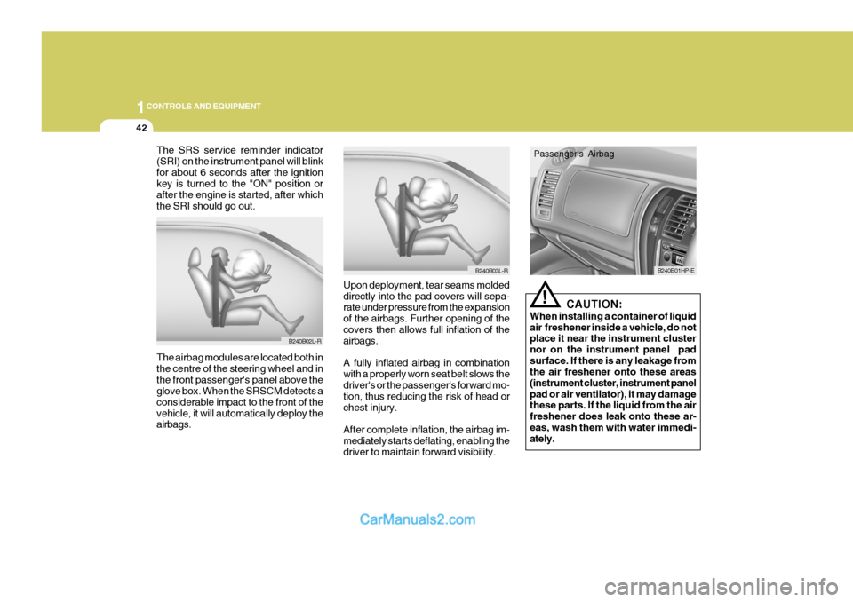
The SRS service reminder indicator (SRI) on the instrument panel will blinkfor about 6 seconds after the ignition key is turned to the "ON" position or after the engine is started, after whichthe SRI should go out.
Upon deployment, tear seams moldeddirectly into the pad covers will sepa- rate under pressure from the expansion of the airbags. Further opening of the covers then allows full inflation of the airbags. A fully inflated airbag in combination with a properly worn seat belt slows thedriver's or the passenger's forward mo-
tion, thus reducing the risk of head or chest injury. After complete inflation, the airbag im- mediately starts deflating, enabling thedriver to maintain forward visibility.
The airbag modules are located both inthe centre of the steering wheel and inthe front passenger's panel above the glove box. When the SRSCM detects a considerable impact to the front of thevehicle, it will automatically deploy the airbags.
B240B02L-R
B240B03L-R
!
CAUTION:
When installing a container of liquid air freshener inside a vehicle, do not place it near the instrument cluster nor on the instrument panel padsurface. If there is any leakage from the air freshener onto these areas (instrument cluster, instrument panelpad or air ventilator), it may damage these parts. If the liquid from the air freshener does leak onto these ar-eas, wash them with water immedi- ately.
B240B01HP-E
Passenger's Airbag
Page 349 of 539
1CONTROLS AND EQUIPMENT
44
!WARNING:
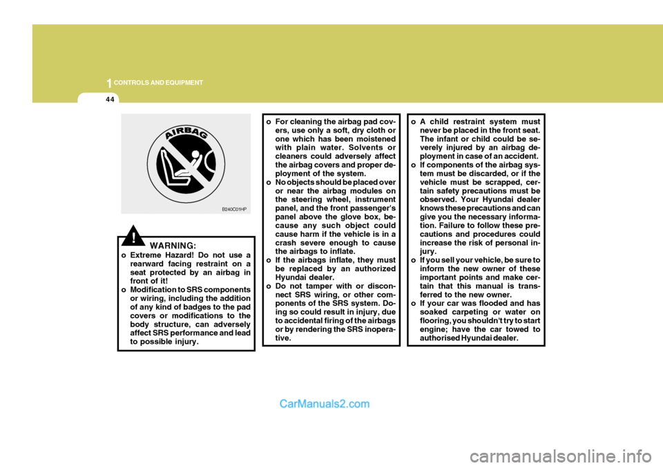
o Extreme Hazard! Do not use a rearward facing restraint on a seat protected by an airbag in front of it!
o Modification to SRS components
or wiring, including the additionof any kind of badges to the pad covers or modifications to thebody structure, can adversely affect SRS performance and lead to possible injury. o For cleaning the airbag pad cov-
ers, use only a soft, dry cloth orone which has been moistened with plain water. Solvents or cleaners could adversely affectthe airbag covers and proper de- ployment of the system.
o No objects should be placed over or near the airbag modules onthe steering wheel, instrument panel, and the front passenger'spanel above the glove box, be- cause any such object could cause harm if the vehicle is in acrash severe enough to cause the airbags to inflate.
o If the airbags inflate, they must be replaced by an authorizedHyundai dealer.
o Do not tamper with or discon- nect SRS wiring, or other com-ponents of the SRS system. Do- ing so could result in injury, dueto accidental firing of the airbags or by rendering the SRS inopera- tive.
B240C01HP
o A child restraint system must
never be placed in the front seat. The infant or child could be se- verely injured by an airbag de- ployment in case of an accident.
o If components of the airbag sys- tem must be discarded, or if thevehicle must be scrapped, cer-tain safety precautions must be observed. Your Hyundai dealer knows these precautions and cangive you the necessary informa- tion. Failure to follow these pre- cautions and procedures couldincrease the risk of personal in- jury.
o If you sell your vehicle, be sure to inform the new owner of theseimportant points and make cer- tain that this manual is trans-ferred to the new owner.
o If your car was flooded and has
soaked carpeting or water onflooring, you shouldn't try to start engine; have the car towed to authorised Hyundai dealer.
Page 405 of 539
1CONTROLS AND EQUIPMENT
100
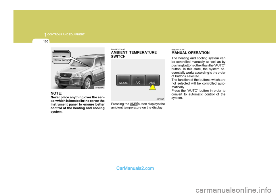
B995A01Y-AAT AMBIENT TEMPERATURE SWITCH Pressing the AMB button displays the ambient temperature on the display. B980A01Y-AAT MANUAL OPERATION The heating and cooling system can be controlled manually as well as by pushing buttons other than the "AUTO" button. In this state, the system se-quentially works according to the order of buttons selected. The function of the buttons which arenot selected will be controlled auto- matically. Press the "AUTO" button in order toconvert to automatic control of the system.
HHP2147
NOTE: Never place anything over the sen- sor which is located in the car on the instrument panel to ensure bettercontrol of the heating and cooling system.
HHP2096
Photo sensor
Page 516 of 539
6
OWNER MAINTENANCE
39
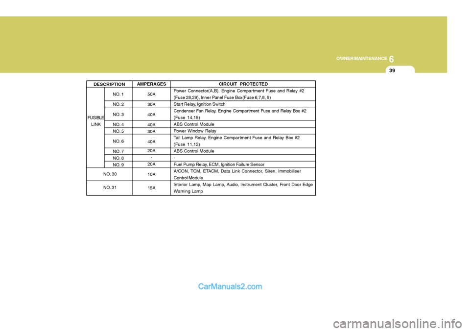
AMPERAGES 50A 30A 40A 40A 30A 40A 20A-
20A 10A
15A
NO. 1
NO. 2
NO. 3
NO. 4
NO. 5
NO. 6
NO. 7
NO. 8
NO. 9
DESCRIPTION
CIRCUIT PROTECTED
Power Connector(A,B), Engine Compartment Fuse and Relay #2
(Fuse 28,29), Inner Panel Fuse Box(Fuse 6,7,8, 9)
Start Relay, Ignition Switch
Condenser Fan Relay, Engine Compar tment Fuse and Relay Box #2(Fuse 14,15)ABS Control Module
Power Window Relay
Tail Lamp Relay, Engine Compartment Fuse and Relay Box #2(Fuse 11,12)ABS Control Module-
Fuel Pump Relay, ECM, Ignition Failure Sensor
A/CON, TCM, ETACM, Data Link Connector, Siren, ImmobiliserControl Module
Interior Lamp, Map Lamp, Audio, Instrument Cluster, Front Door EdgeWarning Lamp
FUSIBLE LINK
NO. 30
NO. 31