dashboard Hyundai Terracan 2005 Owner's Manual
[x] Cancel search | Manufacturer: HYUNDAI, Model Year: 2005, Model line: Terracan, Model: Hyundai Terracan 2005Pages: 539, PDF Size: 18.03 MB
Page 117 of 539
1
FEATURES OF YOUR HYUNDAI
103
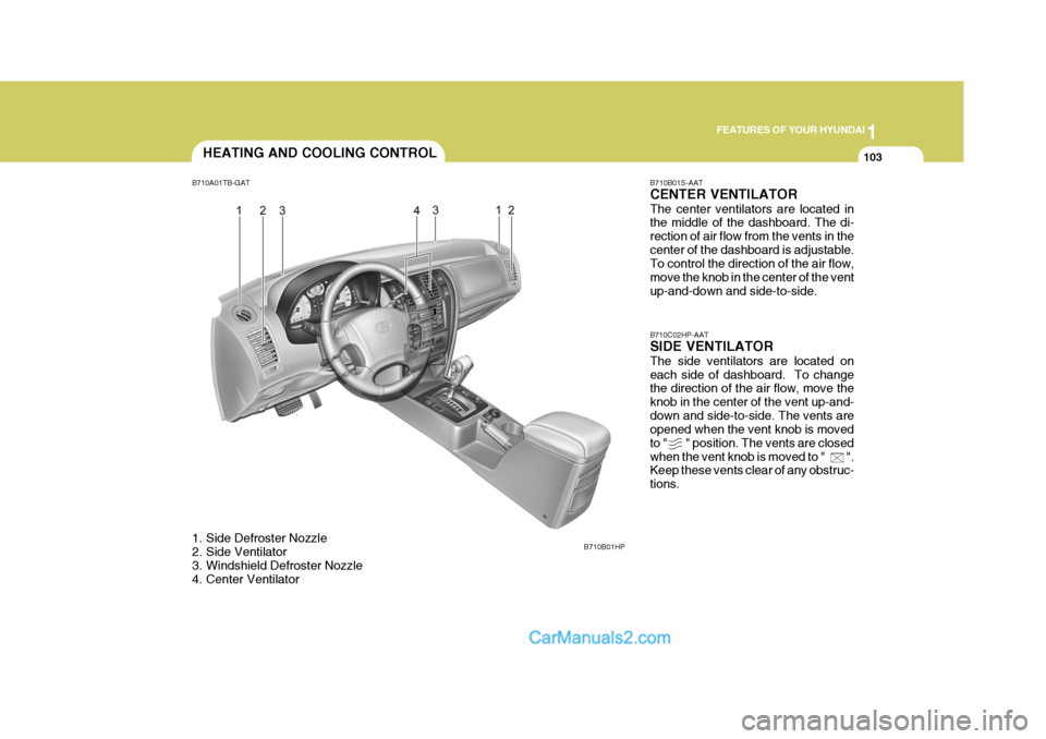
B710B01S-AAT CENTER VENTILATOR The center ventilators are located in the middle of the dashboard. The di- rection of air flow from the vents in thecenter of the dashboard is adjustable. To control the direction of the air flow, move the knob in the center of the ventup-and-down and side-to-side. B710C02HP-AAT SIDE VENTILATOR The side ventilators are located on each side of dashboard. To change the direction of the air flow, move the knob in the center of the vent up-and-down and side-to-side. The vents are opened when the vent knob is moved to " " position. The vents are closedwhen the vent knob is moved to " ". Keep these vents clear of any obstruc- tions.
HEATING AND COOLING CONTROL
B710A01TB-GAT
1. Side Defroster Nozzle
2. Side Ventilator
3. Windshield Defroster Nozzle
4. Center Ventilator B710B01HP
Page 118 of 539
1FEATURES OF YOUR HYUNDAI
104HEATING AND VENTILATION
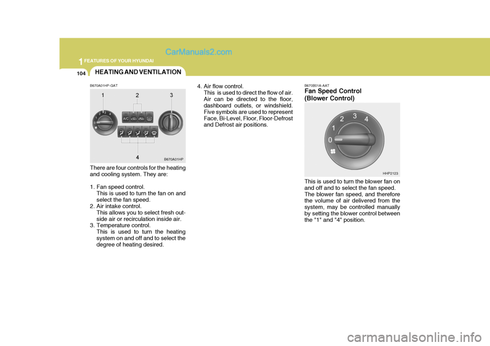
B670A01HP-GAT There are four controls for the heating and cooling system. They are:
1. Fan speed control. This is used to turn the fan on and select the fan speed.
2. Air intake control.
This allows you to select fresh out-side air or recirculation inside air.
3. Temperature control.
This is used to turn the heatingsystem on and off and to select the degree of heating desired. 4. Air flow control.
This is used to direct the flow of air. Air can be directed to the floor, dashboard outlets, or windshield. Five symbols are used to representFace, Bi-Level, Floor, Floor-Defrost and Defrost air positions.
B670A01HP B670B01A-AAT Fan Speed Control (Blower Control) This is used to turn the blower fan on and off and to select the fan speed.The blower fan speed, and therefore the volume of air delivered from the system, may be controlled manuallyby setting the blower control between the "1" and "4" position.
HHP2123
Page 119 of 539
1
FEATURES OF YOUR HYUNDAI
105
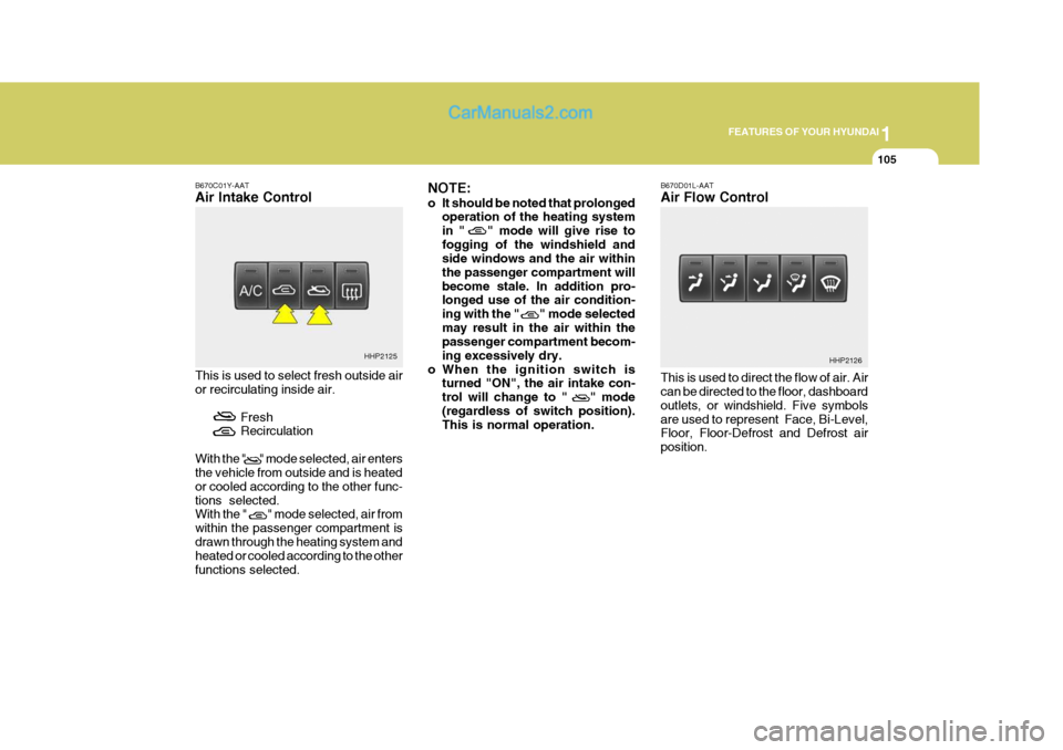
B670C01Y-AAT Air Intake Control This is used to select fresh outside air or recirculating inside air.
FreshRecirculation
With the " " mode selected, air entersthe vehicle from outside and is heated or cooled according to the other func-tions selected. With the " " mode selected, air from within the passenger compartment isdrawn through the heating system and heated or cooled according to the other functions selected. NOTE:
o It should be noted that prolonged
operation of the heating system in " " mode will give rise tofogging of the windshield and side windows and the air within the passenger compartment willbecome stale. In addition pro- longed use of the air condition- ing with the " " mode selectedmay result in the air within the passenger compartment becom- ing excessively dry.
o When the ignition switch is turned "ON", the air intake con-trol will change to " " mode(regardless of switch position). This is normal operation. B670D01L-AAT Air Flow Control This is used to direct the flow of air. Air can be directed to the floor, dashboard outlets, or windshield. Five symbolsare used to represent Face, Bi-Level, Floor, Floor-Defrost and Defrost air position.
HHP2125
HHP2126
Page 120 of 539
1FEATURES OF YOUR HYUNDAI
106
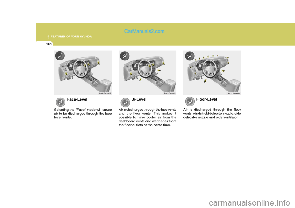
Face-Level
Selecting the "Face" mode will cause air to be discharged through the face level vents. Bi-Level
Air is discharged through the face ventsand the floor vents. This makes it possible to have cooler air from thedashboard vents and warmer air from the floor outlets at the same time. Floor-Level
Air is discharged through the floorvents, windshield defroster nozzle, side defroster nozzle and side ventilator.
B670D01HP B670D02HP
B670D03HP
Page 130 of 539
1FEATURES OF YOUR HYUNDAI
116
o When the ignition switch is
turned "ON", the air intake con- trol will change to ( ) mode (regardless of the switch posi- tion). This is normal operation.The air intake control operates in "AUTO" mode when turning the ignition to the "ON" positionif the "AUTO" mode was used before shutting off the engine.
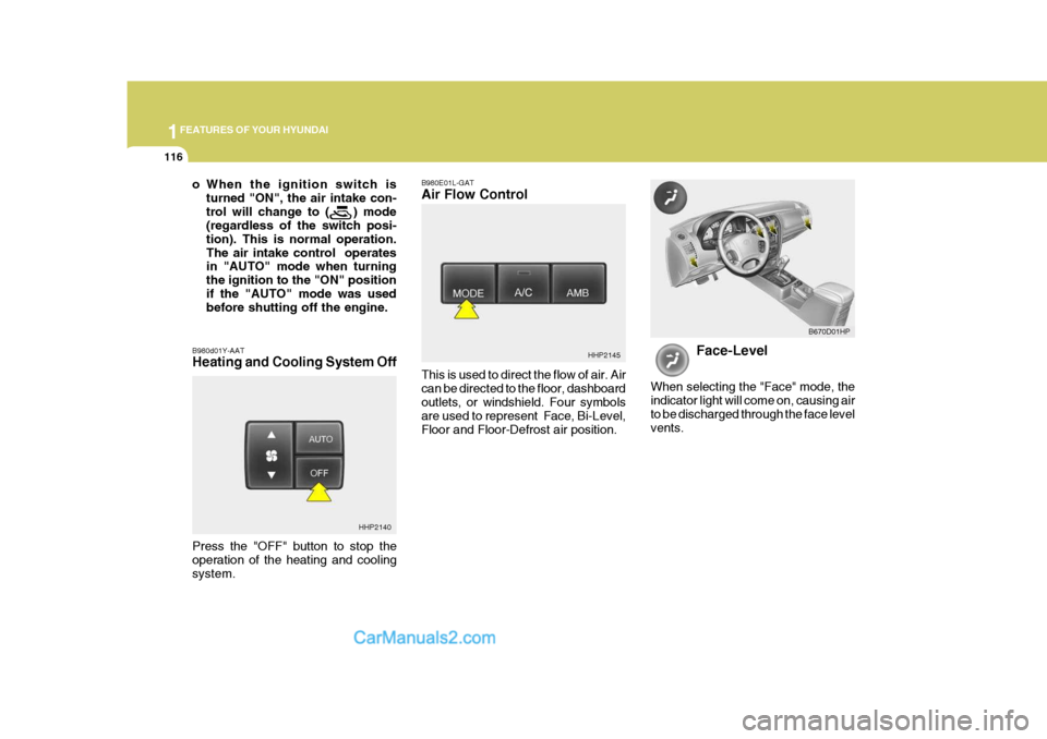
B980d01Y-AAT Heating and Cooling System Off B980E01L-GAT Air Flow Control This is used to direct the flow of air. Air can be directed to the floor, dashboardoutlets, or windshield. Four symbols are used to represent Face, Bi-Level, Floor and Floor-Defrost air position.
HHP2145
Face-Level
When selecting the "Face" mode, the indicator light will come on, causing airto be discharged through the face level vents. B670D01HP
HHP2140
Press the "OFF" button to stop the operation of the heating and coolingsystem.
Page 131 of 539
1
FEATURES OF YOUR HYUNDAI
117
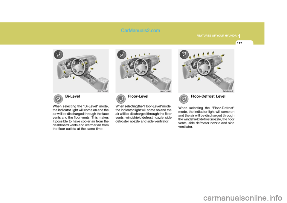
Bi-Level
When selecting the "Bi-Level" mode, the indicator light will come on and theair will be discharged through the face vents and the floor vents. This makes it possible to have cooler air from thedashboard vents and warmer air from the floor outlets at the same time. Floor-Level
When selecting the "Floor-Level" mode, the indicator light will come on and theair will be discharged through the floor vents, windshield defrost nozzle, side defroster nozzle and side ventilator. Floor-Defrost Level
When selecting the "Floor-Defrost"mode, the indicator light will come on and the air will be discharged through the windshield defrost nozzle, the floorvents, side defroster nozzle and side ventilator.
B670D02HP B670D04HPB670D03HP
Page 154 of 539
1FEATURES OF YOUR HYUNDAI
140ANTENNA
!
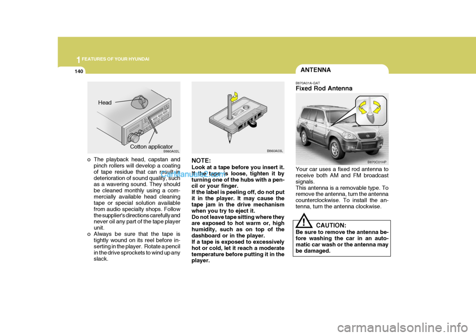
B870A01A-GAT Fixed Rod Antenna Your car uses a fixed rod antenna to receive both AM and FM broadcast signals.This antenna is a removable type. To remove the antenna, turn the antenna counterclockwise. To install the an-tenna, turn the antenna clockwise.
CAUTION:
Be sure to remove the antenna be-fore washing the car in an auto- matic car wash or the antenna may be damaged.
o The playback head, capstan and pinch rollers will develop a coating of tape residue that can result in deterioration of sound quality, such as a wavering sound. They should be cleaned monthly using a com-mercially available head cleaning tape or special solution available from audio specialty shops. Followthe supplier's directions carefully and never oil any part of the tape player unit.
o Always be sure that the tape is tightly wound on its reel before in-serting in the player. Rotate a pencilin the drive sprockets to wind up any slack. NOTE: Look at a tape before you insert it. If the tape is loose, tighten it byturning one of the hubs with a pen- cil or your finger. If the label is peeling off, do not putit in the player. It may cause the tape jam in the drive mechanism when you try to eject it.Do not leave tape sitting where they are exposed to hot warm or, high humidity, such as on top of thedashboard or in the player. If a tape is exposed to excessively hot or cold, let it reach a moderatetemperature before putting it in the player.B860A03L
Head
Cotton applicator B860A02LB870C01HP
Page 253 of 539
6
DO-IT-YOURSELF MAINTENANCE
31
G200B02HP-GAT
Replacing Accessory Fuses
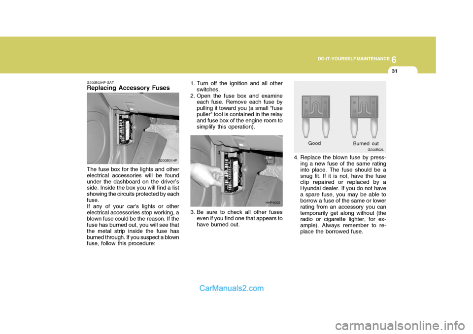
The fuse box for the lights and other electrical accessories will be foundunder the dashboard on the driver’s side. Inside the box you will find a list showing the circuits protected by eachfuse.If any of your car's lights or otherelectrical accessories stop working, ablown fuse could be the reason. If the fuse has burned out, you will see that the metal strip inside the fuse hasburned through. If you suspect a blown fuse, follow this procedure: G200B01HP
4. Replace the blown fuse by press-
ing a new fuse of the same rating into place. The fuse should be asnug fit. If it is not, have the fuse clip repaired or replaced by a Hyundai dealer. If you do not havea spare fuse, you may be able to borrow a fuse of the same or lower rating from an accessory you cantemporarily get along without (the radio or cigarette lighter, for ex- ample). Always remember to re-place the borrowed fuse.
3. Be sure to check all other fuses
even if you find one that appears tohave burned out. Good
1. Turn off the ignition and all other
switches.
2. Open the fuse box and examine each fuse. Remove each fuse bypulling it toward you (a small "fusepuller" tool is contained in the relay and fuse box of the engine room to simplify this operation).
HHP4002 G200B02L
Burned out
Page 394 of 539
1
CONTROLS AND EQUIPMENT
89
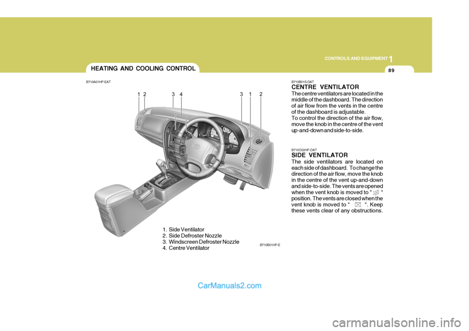
B710B01S-DAT CENTRE VENTILATOR The centre ventilators are located in the middle of the dashboard. The direction of air flow from the vents in the centreof the dashboard is adjustable. To control the direction of the air flow, move the knob in the centre of the ventup-and-down and side-to-side. B710C02HP-DAT SIDE VENTILATOR The side ventilators are located on each side of dashboard. To change the direction of the air flow, move the knob in the centre of the vent up-and-downand side-to-side. The vents are opened when the vent knob is moved to " " position. The vents are closed when thevent knob is moved to " ". Keep these vents clear of any obstructions.
HEATING AND COOLING CONTROL
B710A01HP-EAT
1. Side Ventilator
2. Side Defroster Nozzle
3. Windscreen Defroster Nozzle
4. Centre Ventilator B710B01HP-E
Page 395 of 539
1CONTROLS AND EQUIPMENT
90
B670B01A-AAT Fan Speed Control (Blower Con- trol)
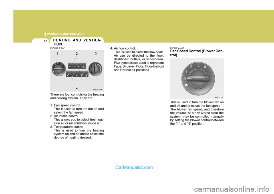
There are four controls for the heating and cooling system. They are:
1. Fan speed control. This is used to turn the fan on and select the fan speed.
2. Air intake control. This allows you to select fresh out-side air or recirculation inside air.
3. Temperature control. This is used to turn the heatingsystem on and off and to select the degree of heating desired. 4. Air flow control.
This is used to direct the flow of air.Air can be directed to the floor, dashboard outlets, or windscreen. Five symbols are used to representFace, Bi-Level, Floor, Floor-Defrost and Defrost air positions.
This is used to turn the blower fan on and off and to select the fan speed. The blower fan speed, and therefore the volume of air delivered from thesystem, may be controlled manually by setting the blower control between the "1" and "4" position.
B670A01HP
HHP2123
HEATING AND VENTILA- TION
B670A01HP-EAT