sensor Hyundai Tiburon 2007 User Guide
[x] Cancel search | Manufacturer: HYUNDAI, Model Year: 2007, Model line: Tiburon, Model: Hyundai Tiburon 2007Pages: 269, PDF Size: 10.37 MB
Page 175 of 269

38WHAT TO DO IN AN EMERGENCY
!!
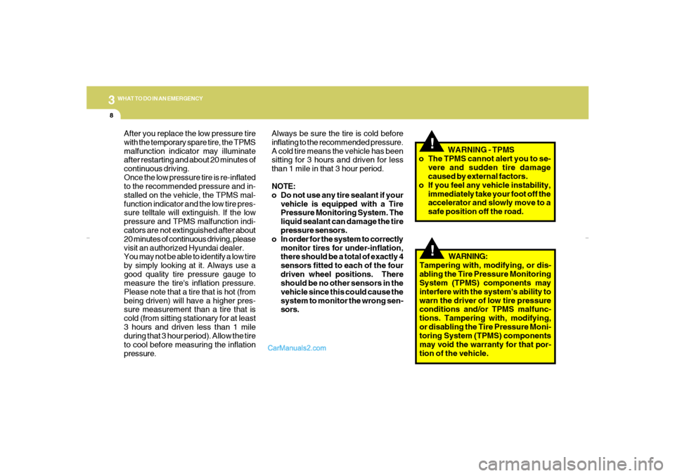
After you replace the low pressure tire
with the temporary spare tire, the TPMS
malfunction indicator may illuminate
after restarting and about 20 minutes of
continuous driving.
Once the low pressure tire is re-inflated
to the recommended pressure and in-
stalled on the vehicle, the TPMS mal-
function indicator and the low tire pres-
sure telltale will extinguish. If the low
pressure and TPMS malfunction indi-
cators are not extinguished after about
20 minutes of continuous driving, please
visit an authorized Hyundai dealer.
You may not be able to identify a low tire
by simply looking at it. Always use a
good quality tire pressure gauge to
measure the tire's inflation pressure.
Please note that a tire that is hot (from
being driven) will have a higher pres-
sure measurement than a tire that is
cold (from sitting stationary for at least
3 hours and driven less than 1 mile
during that 3 hour period). Allow the tire
to cool before measuring the inflation
pressure.Always be sure the tire is cold before
inflating to the recommended pressure.
A cold tire means the vehicle has been
sitting for 3 hours and driven for less
than 1 mile in that 3 hour period.
NOTE:
o Do not use any tire sealant if your
vehicle is equipped with a Tire
Pressure Monitoring System. The
liquid sealant can damage the tire
pressure sensors.
o In order for the system to correctly
monitor tires for under-inflation,
there should be a total of exactly 4
sensors fitted to each of the four
driven wheel positions. There
should be no other sensors in the
vehicle since this could cause the
system to monitor the wrong sen-
sors.WARNING - TPMS
o The TPMS cannot alert you to se-
vere and sudden tire damage
caused by external factors.
o If you feel any vehicle instability,
immediately take your foot off the
accelerator and slowly move to a
safe position off the road.
WARNING:
Tampering with, modifying, or dis-
abling the Tire Pressure Monitoring
System (TPMS) components may
interfere with the system's ability to
warn the driver of low tire pressure
conditions and/or TPMS malfunc-
tions. Tampering with, modifying,
or disabling the Tire Pressure Moni-
toring System (TPMS) components
may void the warranty for that por-
tion of the vehicle.
gkflhma-3.p659/12/2006, 3:21 PM 8
Page 235 of 269

6
DO-IT-YOURSELF MAINTENANCE
35
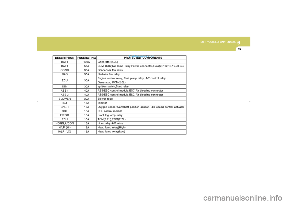
PROTECTED COMPONENTS
Generator(2.0L)
BCM BOX(Tail lamp relay,Power connector,Fuse(2,7,12,13,19,20,24)
Condenser fan relay
Radiator fan relay
Engine control relay, Fuel pump relay, A/T control relay,
Generator, PCM(2.0L)
Ignition switch,Start relay
ABS/ESC control module,ESC Air bleeding connector
ABS/ESC control module,ESC Air bleeding connector
Blower relay
Injector
Oxygen sensor,Camshaft position sensor, Idle speed control actuator
DRL control module
Front fog lamp relay
TCM(2.7L),ECM(2.7L)
Horn relay,A/C relay
Head lamp relay(High)
Head lamp relay(Low)
FUSERATING
120A
50A
30A
30A
30A
30A
40A
40A
30A
15A
10A
15A
15A
10A
15A
15A
15A DESCRIPTION
BATT
BATT
COND
RAD
ECU
IGN
ABS 1
ABS 2
BLOWER
INJ
SNSR
DRL
F/FOG
ECU
HORN,A/CON
H/LP (HI)
H/LP (LO)
gkflhma-6.p659/12/2006, 3:24 PM 35
Page 237 of 269

6
DO-IT-YOURSELF MAINTENANCE
37
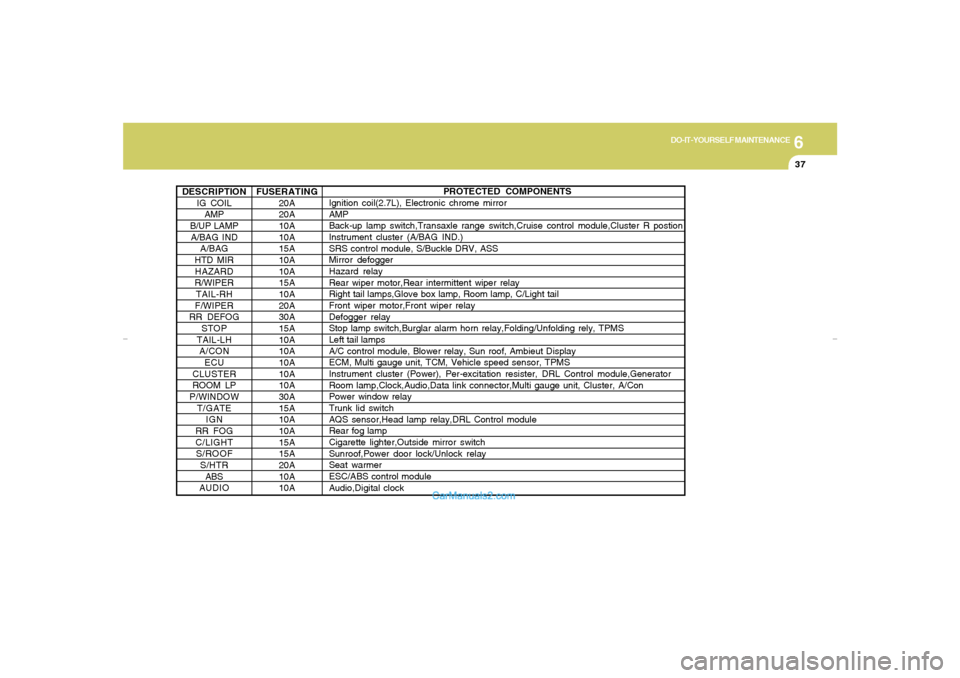
DESCRIPTION
IG COIL
AMP
B/UP LAMP
A/BAG IND
A/BAG
HTD MIR
HAZARD
R/WIPER
TAIL-RH
F/WIPER
RR DEFOG
STOP
TAIL-LH
A/CON
ECU
CLUSTER
ROOM LP
P/WINDOW
T/GATE
IGN
RR FOG
C/LIGHT
S/ROOF
S/HTR
ABS
AUDIO
PROTECTED COMPONENTS
Ignition coil(2.7L), Electronic chrome mirror
AMP
Back-up lamp switch,Transaxle range switch,Cruise control module,Cluster R postion
Instrument cluster (A/BAG IND.)
SRS control module, S/Buckle DRV, ASS
Mirror defogger
Hazard relay
Rear wiper motor,Rear intermittent wiper relay
Right tail lamps,Glove box lamp, Room lamp, C/Light tail
Front wiper motor,Front wiper relay
Defogger relay
Stop lamp switch,Burglar alarm horn relay,Folding/Unfolding rely, TPMS
Left tail lamps
A/C control module, Blower relay, Sun roof, Ambieut Display
ECM, Multi gauge unit, TCM, Vehicle speed sensor, TPMS
Instrument cluster (Power), Per-excitation resister, DRL Control module,Generator
Room lamp,Clock,Audio,Data link connector,Multi gauge unit, Cluster, A/Con
Power window relay
Trunk lid switch
AQS sensor,Head lamp relay,DRL Control module
Rear fog lamp
Cigarette lighter,Outside mirror switch
Sunroof,Power door lock/Unlock relay
Seat warmer
ESC/ABS control module
Audio,Digital clock FUSERATING
20A
20A
10A
10A
15A
10A
10A
15A
10A
20A
30A
15A
10A
10A
10A
10A
10A
30A
15A
10A
10A
15A
15A
20A
10A
10A
gkflhma-6.p659/12/2006, 3:24 PM 37
Page 239 of 269

7
EMISSION CONTROL SYSTEMS2
EMISSION CONTROL SYSTEM
H010D01A-AAT3. Exhaust Emission Control SystemThe Exhaust Emission Control System is a
highly effective system which controls exhaust
emissions while maintaining good vehicle per-
formance.
H010B01A-AAT1. Crankcase Emission Control
SystemThe Positive Crankcase Ventilation System is
employed to prevent air pollution caused by
blow-by gases being emitted from the crank-
case. This system supplies fresh filtered air to
the crankcase through the air intake hose.
Inside the crankcase, the fresh air mixes with
blow-by gases, which then pass through the
PCV valve and into the induction system.
H010A03GK-AATYour Hyundai is equipped with an emission
control system to meet all requirements of the
U.S. Environmental Protection Agency or Cali-
fornia Air Resources Board.
There are three emission control systems which
are as follows.
1) Crankcase Emission Control System
2) Evaporative Emission Control System
3) Exhaust Emission Control System
In order to ensure the proper function of the
emission control systems, it is recommended
that you have your car inspected and main-
tained by an authorized Hyundai dealer in ac-
cordance with the maintenance schedule in this
manual.
Caution for the Inspection and Maintenance
Test (Vehicle with Electronic Stability Con-
trol)
o To prevent the vehicle from misfiring
during dynamometer testing, discon-
nect the ABS connector located inside
of the wheel guard (driver side).
o For more information, see shop manual
(BR Group, Wheel Speed Sensor).
CanisterFuel vapors generated inside the fuel tank are
absorbed and stored in the onboard canister.
When the engine is running, the fuel vapors
absorbed in the canister are drawn into the
induction system through the purge control
solenoid valve.Purge Control Solenoid Valve (PCSV)The purge control solenoid valve is controlled
by the Engine Control Module (ECM); when the
engine coolant temperature is low during idling,
the PCSV closes so that evaporated fuel is not
taken into the engine. After the engine warms-
up during ordinary driving, the PCSV opens to
introduce evaporated fuel to the engine.
H010C01S-AAT2. Evaporative Emission Control (Includ-
ing ORVR: Onboard Refueling Vapor
Recovery) SystemThe Evaporative Emission Control System is
designed to prevent fuel vapors from escaping
into the atmosphere.
(The ORVR system is designed to allow the
vapors from the fuel tank to be loaded into a
canister while refueling at the gas station, pre-
venting the escape of fuel vapors into the
atmosphere.)
gkflhma-7.p659/12/2006, 3:30 PM 2