Hyundai Tiburon 2008 Owner's Manual
Manufacturer: HYUNDAI, Model Year: 2008, Model line: Tiburon, Model: Hyundai Tiburon 2008Pages: 268, PDF Size: 9.93 MB
Page 231 of 268
6
DO-IT-YOURSELF MAINTENANCE
31
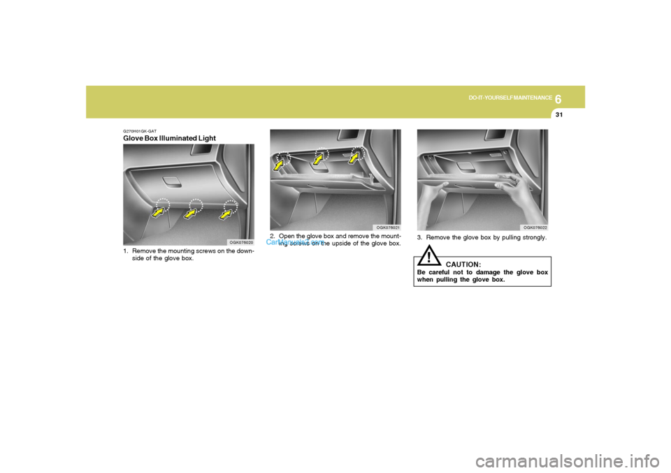
3. Remove the glove box by pulling strongly.
CAUTION:
Be careful not to damage the glove box
when pulling the glove box.
!
OGK076022
OGK076021
2. Open the glove box and remove the mount-
ing screws on the upside of the glove box.
G270H01GK-GATGlove Box Illuminated Light1. Remove the mounting screws on the down-
side of the glove box.
OGK076020
Page 232 of 268
6
DO-IT-YOURSELF MAINTENANCE
32
OGK076038
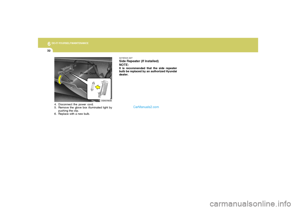
ClipPower Cord
4. Disconnect the power cord.
5. Remove the glove box illuminated light by
pushing the clip.
6. Replace with a new bulb.
G270E02A-GATSide Repeater (If Installed)
NOTE:It is recommended that the side repeater
bulb be replaced by an authorized Hyundai
dealer.
Page 233 of 268
6
DO-IT-YOURSELF MAINTENANCE
33
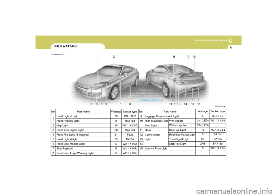
Part Name
Luggage Compartment Light
High Mounted Rear
Stop Light
Rear
Combination
Light
License Plate Light
BULB WATTAGEG280A04GK-AATNo.
1
2
3
4
5
6
7
8Part Name
Head Light (Low)
Front Position Light
Map Light
Front Turn Signal Light
Front Fog Light (If installed)
Head Light (High)
Front Side Marker Light
Side Repeater
Front Door Edge Warning LightWattage
55
8
10
28
51
55
5
5
5No.
9
10
11
12
13
14
15Wattage
5
2.4 (LED)
3.5 (LED)
16
5
27
27/8
5
OGK066009N
Socket type
PGJ 19-2
BAY15d
W2.1 X 9.5D
BAY15d
P22d
Px26d
W2.1 X 9.5d
W2.1 X 9.5d
W2.1 X 9.5dWith spoiler
Without spoiler
Back-up Light
Rear Side Marker Light
Turn Signal Light
Stop/Tail LightSocket type
S8.5 / 8.5
W2.1 X 9.5d
-
W2.1 X 9.5d
BA15s
BA15s
BAY15d
W2.1 X 9.6d
Page 234 of 268
6
DO-IT-YOURSELF MAINTENANCE
34
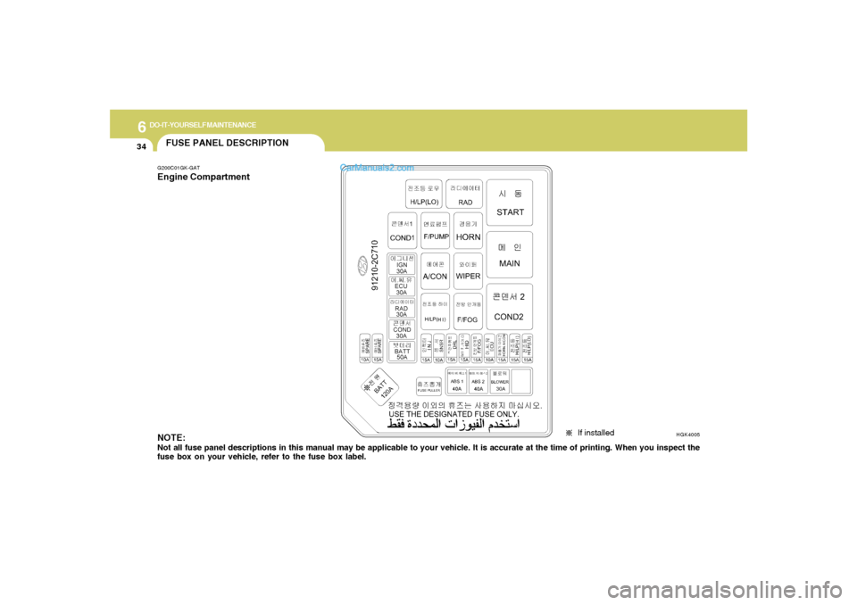
FUSE PANEL DESCRIPTIONG200C01GK-GATEngine Compartment
If installed
NOTE:Not all fuse panel descriptions in this manual may be applicable to your vehicle. It is accurate at the time of printing. When you inspect the
fuse box on your vehicle, refer to the fuse box label.
HGK4005
Page 235 of 268
6
DO-IT-YOURSELF MAINTENANCE
35
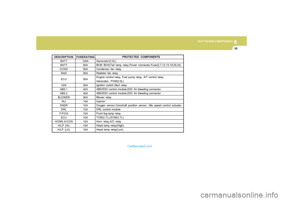
PROTECTED COMPONENTS
Generator(2.0L)
BCM BOX(Tail lamp relay,Power connector,Fuse(2,7,12,13,19,20,24)
Condenser fan relay
Radiator fan relay
Engine control relay, Fuel pump relay, A/T control relay,
Generator, PCM(2.0L)
Ignition switch,Start relay
ABS/ESC control module,ESC Air bleeding connector
ABS/ESC control module,ESC Air bleeding connector
Blower relay
Injector
Oxygen sensor,Camshaft position sensor, Idle speed control actuator
DRL control module
Front fog lamp relay
TCM(2.7L),ECM(2.7L)
Horn relay,A/C relay
Head lamp relay(High)
Head lamp relay(Low)
FUSERATING
120A
50A
30A
30A
30A
30A
40A
40A
30A
15A
10A
15A
15A
10A
15A
15A
15A DESCRIPTION
BATT
BATT
COND
RAD
ECU
IGN
ABS 1
ABS 2
BLOWER
INJ
SNSR
DRL
F/FOG
ECU
HORN,A/CON
H/LP (HI)
H/LP (LO)
Page 236 of 268
6
DO-IT-YOURSELF MAINTENANCE
36
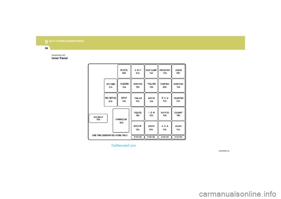
G200D02GK-GATInner Panel
OGK066010L
Page 237 of 268
6
DO-IT-YOURSELF MAINTENANCE
37
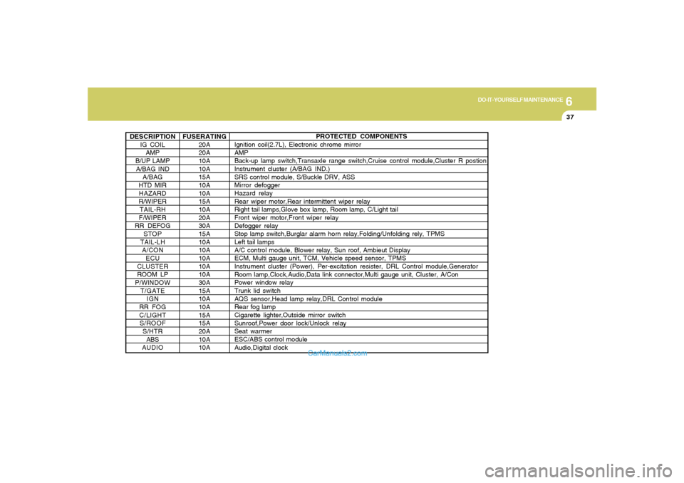
DESCRIPTION
IG COIL
AMP
B/UP LAMP
A/BAG IND
A/BAG
HTD MIR
HAZARD
R/WIPER
TAIL-RH
F/WIPER
RR DEFOG
STOP
TAIL-LH
A/CON
ECU
CLUSTER
ROOM LP
P/WINDOW
T/GATE
IGN
RR FOG
C/LIGHT
S/ROOF
S/HTR
ABS
AUDIO
PROTECTED COMPONENTS
Ignition coil(2.7L), Electronic chrome mirror
AMP
Back-up lamp switch,Transaxle range switch,Cruise control module,Cluster R postion
Instrument cluster (A/BAG IND.)
SRS control module, S/Buckle DRV, ASS
Mirror defogger
Hazard relay
Rear wiper motor,Rear intermittent wiper relay
Right tail lamps,Glove box lamp, Room lamp, C/Light tail
Front wiper motor,Front wiper relay
Defogger relay
Stop lamp switch,Burglar alarm horn relay,Folding/Unfolding rely, TPMS
Left tail lamps
A/C control module, Blower relay, Sun roof, Ambieut Display
ECM, Multi gauge unit, TCM, Vehicle speed sensor, TPMS
Instrument cluster (Power), Per-excitation resister, DRL Control module,Generator
Room lamp,Clock,Audio,Data link connector,Multi gauge unit, Cluster, A/Con
Power window relay
Trunk lid switch
AQS sensor,Head lamp relay,DRL Control module
Rear fog lamp
Cigarette lighter,Outside mirror switch
Sunroof,Power door lock/Unlock relay
Seat warmer
ESC/ABS control module
Audio,Digital clock FUSERATING
20A
20A
10A
10A
15A
10A
10A
15A
10A
20A
30A
15A
10A
10A
10A
10A
10A
30A
15A
10A
10A
15A
15A
20A
10A
10A
Page 238 of 268
EMISSION CONTROL SYSTEMS
7
Emission Control System ............................................. 7-2
Catalytic Converter ....................................................... 7-3
7
gkflhma-7.p659/12/2006, 3:30 PM 1
Page 239 of 268
7
EMISSION CONTROL SYSTEMS2
EMISSION CONTROL SYSTEM
H010D01A-AAT3. Exhaust Emission Control SystemThe Exhaust Emission Control System is a
highly effective system which controls exhaust
emissions while maintaining good vehicle per-
formance.
H010B01A-AAT1. Crankcase Emission Control
SystemThe Positive Crankcase Ventilation System is
employed to prevent air pollution caused by
blow-by gases being emitted from the crank-
case. This system supplies fresh filtered air to
the crankcase through the air intake hose.
Inside the crankcase, the fresh air mixes with
blow-by gases, which then pass through the
PCV valve and into the induction system.
H010A03GK-AATYour Hyundai is equipped with an emission
control system to meet all requirements of the
U.S. Environmental Protection Agency or Cali-
fornia Air Resources Board.
There are three emission control systems which
are as follows.
1) Crankcase Emission Control System
2) Evaporative Emission Control System
3) Exhaust Emission Control System
In order to ensure the proper function of the
emission control systems, it is recommended
that you have your car inspected and main-
tained by an authorized Hyundai dealer in ac-
cordance with the maintenance schedule in this
manual.
Caution for the Inspection and Maintenance
Test (Vehicle with Electronic Stability Con-
trol)
o To prevent the vehicle from misfiring
during dynamometer testing, discon-
nect the ABS connector located inside
of the wheel guard (driver side).
o For more information, see shop manual
(BR Group, Wheel Speed Sensor).
CanisterFuel vapors generated inside the fuel tank are
absorbed and stored in the onboard canister.
When the engine is running, the fuel vapors
absorbed in the canister are drawn into the
induction system through the purge control
solenoid valve.Purge Control Solenoid Valve (PCSV)The purge control solenoid valve is controlled
by the Engine Control Module (ECM); when the
engine coolant temperature is low during idling,
the PCSV closes so that evaporated fuel is not
taken into the engine. After the engine warms-
up during ordinary driving, the PCSV opens to
introduce evaporated fuel to the engine.
H010C01S-AAT2. Evaporative Emission Control (Includ-
ing ORVR: Onboard Refueling Vapor
Recovery) SystemThe Evaporative Emission Control System is
designed to prevent fuel vapors from escaping
into the atmosphere.
(The ORVR system is designed to allow the
vapors from the fuel tank to be loaded into a
canister while refueling at the gas station, pre-
venting the escape of fuel vapors into the
atmosphere.)
gkflhma-7.p659/12/2006, 3:30 PM 2
Page 240 of 268
7
EMISSION CONTROL SYSTEMS
3
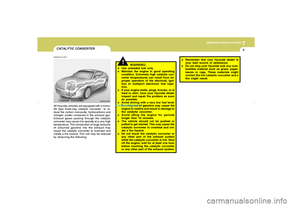
CATALYTIC CONVERTERH020A01A-AATAll Hyundai vehicles are equipped with a mono-
lith type three-way catalytic converter to re-
duce the carbon monoxide, hydrocarbons and
nitrogen oxides contained in the exhaust gas.
Exhaust gases passing through the catalytic
converter may cause it to operate at a very high
temperature. The introduction of large amounts
of unburned gasoline into the exhaust may
cause the catalytic converter to overheat and
create a fire hazard. This risk may be reduced
by observing the following:
Catalytic Converter
!
WARNING:
o Use unleaded fuel only.
o Maintain the engine in good operating
condition. Extremely high catalytic con-
verter temperatures can result from im-
proper operation of the electrical, igni-
tion or multiport electronic fuel injec-
tion.
o If your engine stalls, pings, knocks, or is
hard to start, have your Hyundai dealer
inspect and repair the problem as soon
as possible.
o Avoid driving with a very low fuel level.
Running out of gasoline may cause the
engine to misfire and result in damage to
the catalytic converter.
o Avoid idling the engine for periods
longer than 10 minutes.
o The vehicle should not be pushed or
pulled to get started. This may cause the
catalytic converter to overheat and cre-
ate a fire hazard.
o Do not touch the catalytic converter or
any other part of the exhaust system
while the catalytic converter is hot. Shut
off the engine, wait for at least one hour
before touching the catalytic converter
or any other part of the exhaust system.o Remember that your Hyundai dealer is
your best source of assistance.
o Do not stop your Hyundai over any com-
bustible material such as grass, paper,
leaves or rags. These materials might
contact the hot catalytic converter and a
fire might result.
OGK076501
gkflhma-7.p659/12/2006, 3:30 PM 3