ABS HYUNDAI TUCSON 2012 User Guide
[x] Cancel search | Manufacturer: HYUNDAI, Model Year: 2012, Model line: TUCSON, Model: HYUNDAI TUCSON 2012Pages: 371, PDF Size: 5.39 MB
Page 255 of 371
Driving your vehicle
54
5
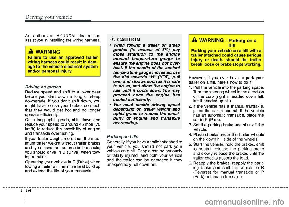
An authorized HYUNDAI dealer can
assist you in installing the wiring harness.
Driving on grades
Reduce speed and shift to a lower gear
before you start down a long or steep
downgrade. If you don’t shift down, you
might have to use your brakes so much
that they would get hot and no longer
operate efficiently.
On a long uphill grade, shift down and
reduce your speed to around 45 mph (70 km/h) to reduce the possibility of engine
and transaxle overheating.
If your trailer weighs more than the max-
imum trailer weight without trailer brakes
and you have an automatic transaxle,
you should drive in D (Drive) when tow-
ing a trailer.
Operating your vehicle in D (Drive) when
towing a trailer will minimize heat build up
and extend the life of your transaxle.
Parking on hills
Generally, if you have a trailer attached to
your vehicle, you should not park your
vehicle on a hill. People can be seriously
or fatally injured, and both your vehicle
and the trailer can be damaged if they
unexpectedly roll down hill. However, if you ever have to park your
trailer on a hill, here's how to do it:
1. Pull the vehicle into the parking space.
Turn the steering wheel in the direction
of the curb (right if headed down hill, left if headed up hill).
2. If the vehicle has a manual transaxle, place the car in neutral. If the vehicle
has an automatic transaxle, place the
car in P (Park).
3. Set the parking brake and shut off the vehicle.
4. Place chocks under the trailer wheels on the down hill side of the wheels.
5. Start the vehicle, hold the brakes, shift to neutral, release the parking brake
and slowly release the brakes until the
trailer chocks absorb the load.
6. Reapply the brakes, reapply the park- ing brake and shift the vehicle to R
(Reverse) for manual transaxle or P
(Park) automatic transaxle.
CAUTION
When towing a trailer on steep
grades (in excess of 6%) payclose attention to the engine
coolant temperature gauge toensure the engine does not over-heat. If the needle of the coolanttemperature gauge moves across
the dial towards “H” (HOT), pullover and stop as soon as it is safe to do so, and allow the engine to
idle until it cools down. You mayproceed once the engine hascooled sufficiently.
You must decide driving speed depending on trailer weight anduphill grade to reduce the possi-bility of engine and transaxle
overheating.
WARNING
Failure to use an approved trailer wiring harness could result in dam-
age to the vehicle electrical system
and/or personal injury.
WARNING- Parking on a hill
Parking your vehicle on a hill with a
trailer attached could cause serious
injury or death, should the trailer
break loose or brake stops working.
Page 328 of 371
741
Maintenance
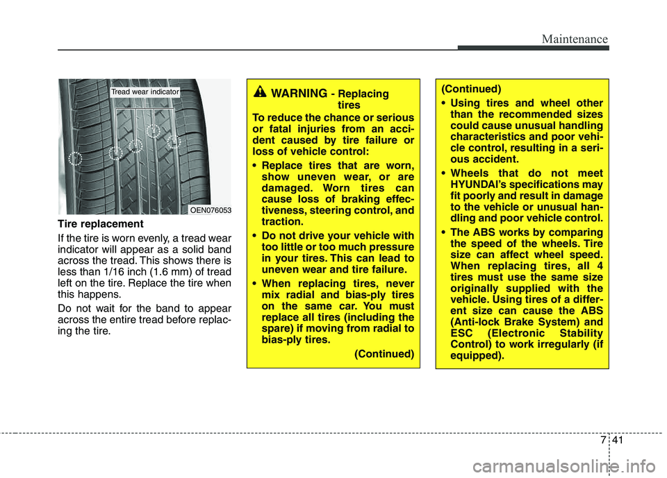
Tire replacement
If the tire is worn evenly, a tread wear indicator will appear as a solid band
across the tread. This shows there isless than 1/16 inch (1.6 mm) of tread
left on the tire. Replace the tire when
this happens.
Do not wait for the band to appear
across the entire tread before replac-
ing the tire.
OEN076053
Tread wear indicatorWARNING - Replacingtires
To reduce the chance or serious
or fatal injuries from an acci-
dent caused by tire failure or
loss of vehicle control:
Replace tires that are worn, show uneven wear, or are
damaged. Worn tires can
cause loss of braking effec-
tiveness, steering control, andtraction.
Do not drive your vehicle with too little or too much pressure
in your tires. This can lead to
uneven wear and tire failure.
When replacing tires, never mix radial and bias-ply tires
on the same car. You must
replace all tires (including the
spare) if moving from radial to
bias-ply tires.
(Continued)(Continued)
Using tires and wheel otherthan the recommended sizes
could cause unusual handling
characteristics and poor vehi-
cle control, resulting in a seri-ous accident.
Wheels that do not meet HYUNDAI’s specifications may
fit poorly and result in damage
to the vehicle or unusual han-
dling and poor vehicle control.
The ABS works by comparing the speed of the wheels. Tire
size can affect wheel speed.
When replacing tires, all 4
tires must use the same size
originally supplied with the
vehicle. Using tires of a differ-
ent size can cause the ABS
(Anti-lock Brake System) and
ESC (Electronic Stability
Control) to work irregularly (ifequipped).
Page 343 of 371
Maintenance
56
7
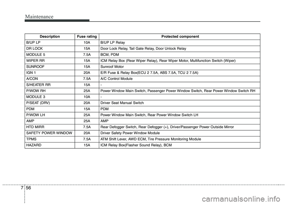
Description Fuse rating Protected component
B/UP LP 10A B/UP LP Relay
DR LOCK 15A Door Lock Relay, Tail Gate Relay, Door Unlock Relay
MODULE 5 7.5A BCM, PDM
WIPER RR 15A ICM Relay Box (Rear Wiper Relay), Rear Wiper Motor, Multifunction Switch (Wiper)
SUNROOF 15A Sunroof Motor
IGN 1 20A E/R Fuse & Relay Box(ECU 2 7.5A, ABS 7.5A, TCU 2 7.5A)
A/CON 7.5A A/C Control Module
S/HEATER RR 15A -
P/WDW RH 25A Power Window Main Switch, Passenger Power Window Switch, Rear Power Window Switch RH
MODULE 3 10A -
P/SEAT (DRV) 20A Driver Seat Manual Switch
PDM 15A PDM
P/WDW LH 25A Power Window Main Switch, Rear Power Window Switch LH
AMP 25A AMP
HTD MIRR 7.5A Rear Defogger Switch, Rear Defogger (+), Driver/Passenger Power Outside Mirror
SAFETY POWER WINDOW 20A Driver Safety Power Window Module
TPMS 7.5A ATM Shift Lever, AWD ECM, Tire Pressure Monitoring Module
HAZARD 15A ICM Relay Box(Flasher Sound Relay), BCM
Page 344 of 371
757
Maintenance
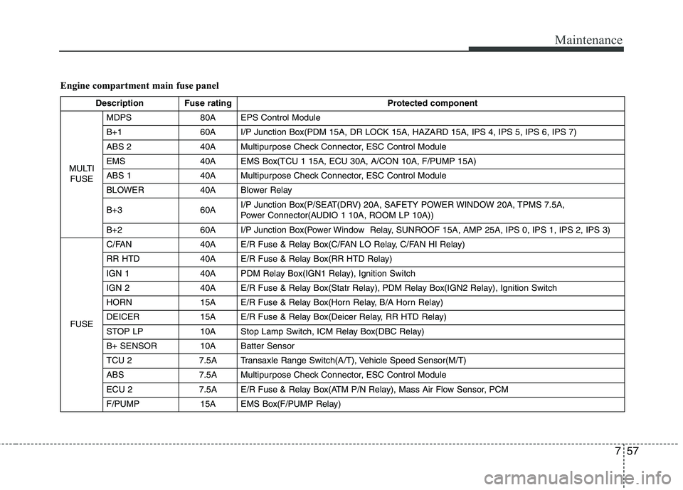
Engine compartment main fuse panel
Description Fuse ratingProtected component
MULTI FUSE MDPS 80A EPS Control Module
B+1 60A I/P Junction Box(PDM 15A, DR LOCK 15A, HAZARD 15A, IPS 4, IPS 5, IPS 6, IPS 7)
ABS 2 40A Multipurpose Check Connector, ESC Control Module
EMS 40A EMS Box(TCU 1 15A, ECU 30A, A/CON 10A, F/PUMP 15A)
ABS 1 40A Multipurpose Check Connector, ESC Control Module
BLOWER 40A Blower Relay
B+3 60A
I/P Junction Box(P/SEAT(DRV) 20A, SAFETY POWER WINDOW 20A, TPMS 7.5A,
Power Connector(AUDIO 1 10A, ROOM LP 10A))
B+2 60A I/P Junction Box(Power Window Relay, SUNROOF 15A, AMP 25A, IPS 0, IPS 1, IPS 2, IPS 3)
FUSE C/FAN 40A E/R Fuse & Relay Box(C/FAN LO Relay, C/FAN HI Relay)
RR HTD 40A E/R Fuse & Relay Box(RR HTD Relay)
IGN 1 40A PDM Relay Box(IGN1 Relay), Ignition Switch
IGN 2 40A E/R Fuse & Relay Box(Statr Relay), PDM Relay Box(IGN2 Relay), Ignition Switch
HORN 15A E/R Fuse & Relay Box(Horn Relay, B/A Horn Relay)
DEICER 15A E/R Fuse & Relay Box(Deicer Relay, RR HTD Relay)
STOP LP 10A Stop Lamp Switch, ICM Relay Box(DBC Relay)
B+ SENSOR 10A Batter Sensor
TCU 2 7.5A Transaxle Range Switch(A/T), Vehicle Speed Sensor(M/T)
ABS 7.5A Multipurpose Check Connector, ESC Control Module
ECU 2 7.5A E/R Fuse & Relay Box(ATM P/N Relay), Mass Air Flow Sensor, PCM
F/PUMP 15A EMS Box(F/PUMP Relay)
Page 348 of 371
761
Maintenance
5. Remove the bulb from the headlightassembly.
6. Install a new headlight bulb and snap the headlight bulb retaining wire into
position by aligning the wire with the
groove on the bulb.
7. Connect the headlight bulb socket- connector.
8. Install the headlight bulb cover by turn- ing it clockwise.
Front fog light bulbs (if equipped)
If the light bulb is not operating, have the
vehicle checked by an authorized
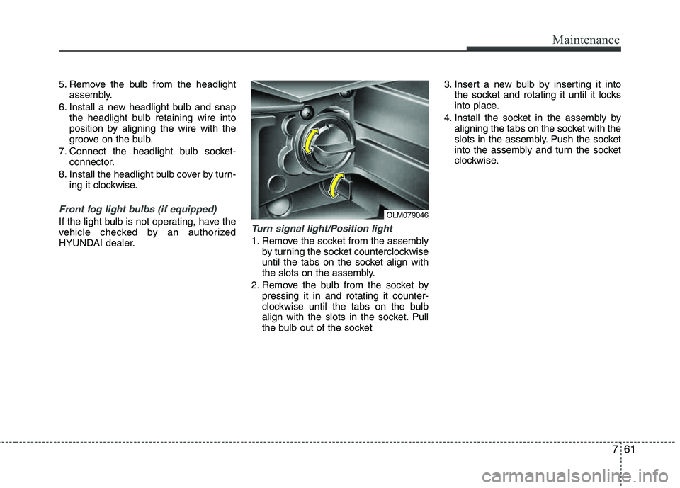
HYUNDAI dealer.Turn signal light/Position light
1. Remove the socket from the assembly by turning the socket counterclockwise
until the tabs on the socket align with
the slots on the assembly.
2. Remove the bulb from the socket by pressing it in and rotating it counter-
clockwise until the tabs on the bulb
align with the slots in the socket. Pull
the bulb out of the socket 3. Insert a new bulb by inserting it into
the socket and rotating it until it locks
into place.
4. Install the socket in the assembly by aligning the tabs on the socket with the
slots in the assembly. Push the socket
into the assembly and turn the socket
clockwise.
OLM079046
Page 350 of 371
763
Maintenance
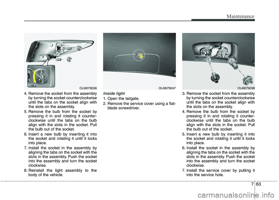
4. Remove the socket from the assemblyby turning the socket counterclockwise
until the tabs on the socket align with
the slots on the assembly.
5. Remove the bulb from the socket by pressing it in and rotating it counter-
clockwise until the tabs on the bulb
align with the slots in the socket. Pull
the bulb out of the socket.
6. Insert a new bulb by inserting it into the socket and rotating it until it locks
into place.
7. Install the socket in the assembly by aligning the tabs on the socket with the
slots in the assembly. Push the socket
into the assembly and turn the socket
clockwise.
8. Reinstall the light assembly to the body of the vehicle.Inside light
1. Open the tailgate.
2. Remove the service cover using a flat- blade screwdriver. 3. Remove the socket from the assembly
by turning the socket counterclockwise
until the tabs on the socket align with
the slots on the assembly.
4. Remove the bulb from the socket by pressing it in and rotating it counter-
clockwise until the tabs on the bulb
align with the slots in the socket. Pull
the bulb out of the socket.
5. Insert a new bulb by inserting it into the socket and rotating it until it locks
into place.
6. Install the socket in the assembly by aligning the tabs on the socket with the
slots in the assembly. Push the socket
into the assembly and turn the socket
clockwise.
7. Install the service cover by putting it into the service hole.
OLM079036OLM079047OLM079038
Page 351 of 371
Maintenance
64
7
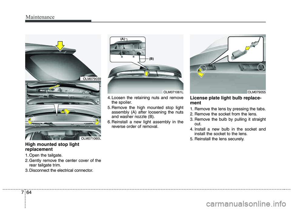
High mounted stop light replacement
1. Open the tailgate.
2. Gently remove the center cover of the
rear tailgate trim.
3. Disconnect the electrical connector. 4. Loosen the retaining nuts and
remove
the spoiler.
5. Remove the high mounted stop light assembly (A) after loosening the nuts
and washer nozzle (B).
6. Reinstall a new light assembly in the reverse order of removal.
License plate light bulb replace- ment
1. Remove the lens by pressing the tabs.
2. Remove the socket from the lens.
3. Remove the bulb by pulling it straight out.
4. Install a new bulb in the socket and install the socket to the lens.
5. Reinstall the lens securely.
OLM071061L
(A)
(B)
OLM071060L
OLM079039
OLM079055
Page 352 of 371
765
Maintenance
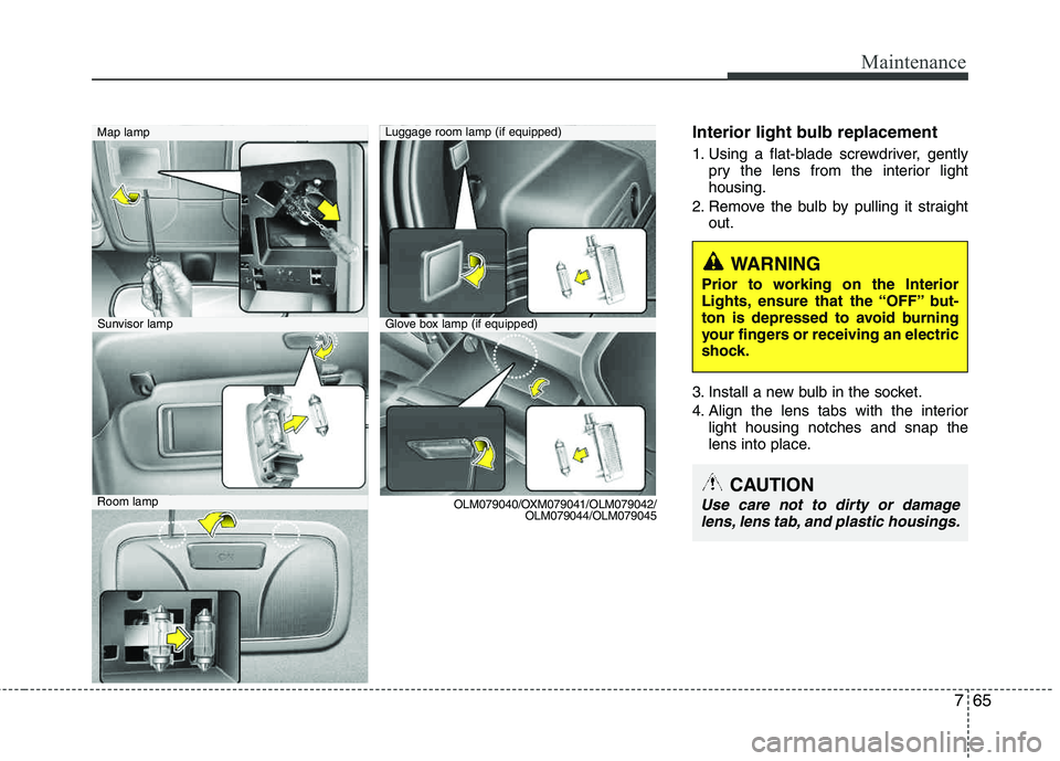
Interior light bulb replacement
1. Using a flat-blade screwdriver, gentlypry the lens from the interior light housing.
2. Remove the bulb by pulling it straight out.
3. Install a new bulb in the socket.
4. Align the lens tabs with the interior light housing notches and snap the
lens into place.
WARNING
Prior to working on the Interior
Lights, ensure that the “OFF” but-
ton is depressed to avoid burning
your fingers or receiving an electric
shock.
Map lampLuggage room lamp (if equipped)
Sunvisor lamp
Room lamp OLM079040/OXM079041/OLM079042/
OLM079044/OLM079045CAUTION
Use care not to dirty or damage
lens, lens tab, and plastic housings.
Glove box lamp (if equipped)
Page 360 of 371
773
Maintenance
Canister
Fuel vapors generated inside the fuel tank are absorbed and stored in the
onboard canister. When the engine is
running, the fuel vapors absorbed in the
canister are drawn into the surge tank
through the purge control solenoid valve.
Purge Control Solenoid Valve (PCSV)
The purge control solenoid valve is con-
trolled by the Engine Control Module
(ECM); when the engine coolant temper-
ature is low during idling, the PCSV clos-
es so that evaporated fuel is not taken
into the engine. After the engine warms-
up during ordinary driving, the PCSV
opens to introduce evaporated fuel to the
engine.
3. Exhaust emission control system
The Exhaust Emission Control System is
a highly effective system which controls
exhaust emissions while maintaining
good vehicle performance.
Vehicle modifications
This vehicle should not be modified.
Modification of your vehicle could affect
its performance, safety or durability and
may even violate governmental safety
and emissions regulations.
In addition, damage or performance
problems resulting from any modification
may not be covered under warranty.
If you use unauthorized electronicdevices, it may cause the vehicle to
operate abnormally, wire damage, bat-
tery discharge and fire. For your safety,
be careful not to damage.
Engine exhaust gas precautions
(carbon monoxide)
Carbon monoxide can be present with other exhaust fumes. Therefore, if you
smell exhaust fumes of any kind inside
your vehicle, have it inspected and
repaired immediately. If you ever sus-
pect exhaust fumes are coming into
your vehicle, drive it only with all the
windows fully open. Have your vehicle
checked and repaired immediately.
WARNING - Exhaust
Engine exhaust gases contain car-
bon monoxide (CO). Though color-
less and odorless, it is dangerousand could be lethal if inhaled.
Follow the instructions on this
page to avoid CO poisoning.
CALIFORNIA PROPOSI-
TION 65 WARNING
Engine exhaust and a wide variety of automobile components and
parts, including components foundin the interior furnishings in a vehi-
cle, contain or emit chemicals
known to the State of California to
cause cancer and birth defects and
reproductive harm. In addition, cer-
tain fluids contained in vehicles
and certain products of component
wear contain or emit chemicals
known to the State of California to
cause cancer and birth defects or
other reproductive harm.