Seat HYUNDAI TUCSON 2013 Manual PDF
[x] Cancel search | Manufacturer: HYUNDAI, Model Year: 2013, Model line: TUCSON, Model: HYUNDAI TUCSON 2013Pages: 397, PDF Size: 5.55 MB
Page 235 of 397
527
Driving your vehicle
✽✽NOTICE
Do not drive in water if the level is higher than the bottom of the vehicle.
Check your brake condition once you
are out of mud or water. Press the
brake pedal several times as you move
slowly until you feel normal braking
forces return.
Shorten your scheduled maintenance interval if you drive in off-road condi-
tions such as sand, mud or water (see
“Maintenance under severe usage
conditions” in section 7). Always wash
your vehicle thoroughly after off road
use, especially cleaning the bottom of
the vehicle.
Since the driving torque is always
applied to the 4 wheels the perform-
ance of the AWD vehicle is greatly
affected by the condition of the tires.
Be sure to equip the vehicle with four
tires of the same size and type.
A full time four wheel drive vehicle cannot be towed by an ordinary tow
truck. Make sure that the vehicle is
placed on a flat bed truck for moving.Reducing the risk of a rollover
This multi-purpose passenger vehicle is
defined as a Sports Utility Vehicle (SUV).
SUV’s have higher ground clearance and
a narrower track to make them capable
of performing in a wide variety of off-road
applications. Specific design characteris-
tics give them a higher center of gravity
than ordinary vehicles. An advantage of
the higher ground clearance is a better
view of the road, which allows you to
anticipate problems. They are not
designed for cornering at the same
speeds as conventional passenger vehi-
cles, any more than low-slung sports
cars are designed to perform satisfactori-
ly in off-road conditions. Due to this risk,
driver and passengers are strongly rec-
ommended to buckle their seat belts. In
a rollover crash, an unbelted person is
more likely to die than a person wearing
a seat belt. There are steps that a driver
can make to reduce the risk of a rollover.
If at all possible, avoid sharp turns or
abrupt maneuvers, do not load your roof
rack with heavy cargo, and never modify
your vehicle in any way.
CAUTION - Mud or snow
If one of the front or rear wheels
begins to spin in mud, snow, etc.the vehicle can sometimes be driv-
en out by depressing the accelera-tor pedal further; however avoid
running the engine continuously athigh rpm because doing so could
damage the AWD system.
WARNING - AWD driving
Avoid high cornering speed.
Do not make quick steering wheel movements, such as sharp
lane changes or fast, sharp turns.
The risk of rollover is greatly increased if you lose control of
your vehicle at high speed.
In a collision, an unbelted person is significantly more likely to die
compared to a person wearing a seat belt.
Loss of control often occurs if two or more wheels drop off the
roadway and the driver over
steers to re-enter the roadway. In
the event your vehicle leaves the
roadway, do not steer sharply.
Instead, slow down before pulling
back into the travel lanes.
Page 236 of 397

Driving your vehicle
28
5
WARNING - Jacked vehicle
While a full-time AWD vehicle is
raised on a jack, never start the
engine or cause the tires to rotate.
There is a danger that rotating tires
touching the ground could cause
the vehicle to fall off the jack and to
jump forward or rearward.
WARNING
Your vehicle is equipped with tires
designed to provide safe ride and
handling capability. Do not use a
size and type of tire and wheel that
is different from the one that is
originally installed on your vehicle.
It can affect the safety and perform-
ance of your vehicle, which could
lead to steering failure or rollover
and serious injury. When replacing
the tires, be sure to equip all four tires with the tire and wheel of the
same size, type, tread, brand and
load-carrying capacity. If you never-
theless decide to equip your vehi-
cle with any tire/wheel combination
not recommended by HYUNDAI for
off road driving, you should not use
these tires for highway driving.WARNING - Rollover
As with other Sports Utility Vehicle
(SUV), failure to operate this vehi-
cle correctly may result in loss of
control, an accident or vehicle
rollover.
Utility vehicles have a significant- ly higher rollover rate than other
types of vehicles.
Specific design characteristics (higher ground clearance, nar-
rower track, etc.) give this vehicle
a higher center of gravity than
ordinary vehicles.
A SUV is not designed for corner- ing at the same speeds as con-
ventional vehicles.
Avoid sharp turns or abrupt maneuvers.
In a rollover crash, an unbelted person is significantly more like-
ly to die than a person wearing a
seat belt. Make sure everyone in
the vehicle is properly buckledup.
Page 272 of 397
Driving your vehicle
64
5
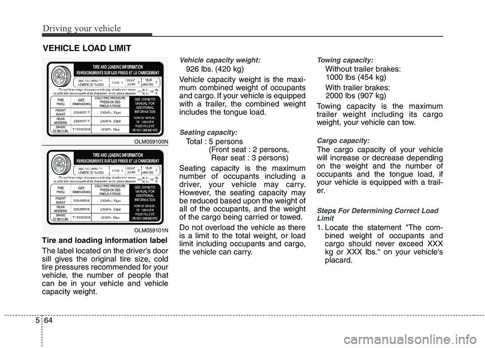
Tire and loading information label
The label located on the driver's door
sill gives the original tire size, cold
tire pressures recommended for your
vehicle, the number of people that
can be in your vehicle and vehicle
capacity weight.
Vehicle capacity weight:
926 lbs. (420 kg)
Vehicle capacity weight is the maxi-
mum combined weight of occupants
and cargo. If your vehicle is equipped
with a trailer, the combined weightincludes the tongue load.
Seating capacity:
Total : 5 persons (Front seat : 2 persons, Rear seat : 3 persons)
Seating capacity is the maximum
number of occupants including a
driver, your vehicle may carry.
However, the seating capacity may
be reduced based upon the weight of
all of the occupants, and the weight
of the cargo being carried or towed.
Do not overload the vehicle as there
is a limit to the total weight, or load
limit including occupants and cargo,
the vehicle can carry.
Towing capacity:
Without trailer brakes: 1000 lbs (454 kg)
With trailer brakes: 2000 lbs (907 kg)
Towing capacity is the maximum
trailer weight including its cargo
weight, your vehicle can tow.
Cargo capacity:
The cargo capacity of your vehicle will increase or decrease depending
on the weight and the number ofoccupants and the tongue load, if
your vehicle is equipped with a trail-
er.
Steps For Determining Correct Load Limit
1. Locate the statement "The com-
bined weight of occupants and
cargo should never exceed XXX
kg or XXX lbs.'' on your vehicle'splacard.
VEHICLE LOAD LIMIT
OLM059100N
OLM059101N
Page 273 of 397

565
Driving your vehicle
2. Determine the combined weight ofthe driver and passengers that will
be riding in your vehicle.
3. Subtract the combined weight of the driver and passengers from
XXX kg or XXX lbs.
4. The resulting figure equals the available amount of cargo and lug-
gage load capacity. For example, ifthe "XXX" amount equals 1400
lbs. and there will be five 150 lbs.
passengers in your vehicle, the
amount of available cargo and lug-gage load capacity is 650 lb
(1400-750 (5 x 150) = 650 lbs.)
5. Determine the combined weight of luggage and cargo being loaded
on the vehicle. That weight may
not safely exceed the availablecargo and luggage load capacitycalculated in Step 4.
6. If your vehicle will be towing a trail- er, load from your trailer will be
transferred to your vehicle. Consult
this manual to determine how this
reduces the available cargo and
luggage load capacity of your
vehicle. Refer to your vehicle’s tire and loading information label for specific informa-
tion about your vehicle's capacity weight and seating positions. The com-
bined weight of the driver, passengers and cargo should never exceed your
vehicle's capacity weight.
C190F01JM
Item Description Total
A Vehicle Capacity 1400 lbs
Weight (635 kg)
Subtract Occupant
B Weight 300 lbs
150 lbs (68 kg) × 2 (136 kg)
C
Available Cargo and1100 lbs
Luggage weight (499 kg)
Example 1
ABC
C190F02JM
Item Description TotalA Vehicle Capacity 1400 lbs
Weight (635 kg)
Subtract Occupant
B Weight 750 lbs
150 lbs (68 kg) × 5 (340 kg)
C
Available Cargo and650 lbs
Luggage weight (295 kg)
ABC
Example 2
Page 275 of 397

567
Driving your vehicle
The label will help you decide how
much cargo and installed equipment
your vehicle can carry.
If you carry items inside your vehicle
- like suitcases, tools, packages, or
anything else - they are moving as
fast as the vehicle. If you have to stop
or turn quickly, or if there is a crash,
the items will keep going and can
cause an injury if they strike the driv-
er or a passenger.
(Continued)
Do not load your vehicle anyheavier than the GVWR, either
the maximum front or rear
GAWR and vehicle capacity
weight. If you do, parts,
including tires on your vehicle
can break, and it can change
the way your vehicle handles
and braking ability. This could
cause you to lose control and
crash. Also, overloading can
shorten the life of your vehi-
cle.WARNING
Overloading your vehicle can cause heat buildup in your
vehicle's tires and possibletire failure that could lead to acrash.
Overloading your vehicle can cause increased stopping dis-tances that could lead to acrash.
A crash resulting from poor handling vehicle damage, tire
failure, or increased stoppingdistances could result in seri-
ous injury or death.
WARNING - Loose cargo
Items you carry inside your
vehicle can strike and injure
occupants in a sudden stop or
turn, or in a crash.
Put items in the cargo area of your vehicle. Try to spread the
weight evenly.
Never stack items, like suit- cases, inside the vehicle
above the tops of the seats.
Do not leave an unsecured child restraint in your vehicle.
When you carry something inside the vehicle, secure it.
Do not drive with a seat folded down unless necessary.
CAUTION
Overloading your vehicle may
cause damage. Repairs wouldnot be covered by your warran-ty. Do not overload your vehicle.
Using heavier suspension com- ponents to get added durabilitymight not change your weight
ratings. Ask your dealer to helpyou load your vehicle the right
way.
Page 292 of 397
What to do in an emergency
16
6
10. To reinstall the wheel, hold it on
the studs, put the wheel nuts on the studs and tighten them finger
tight. Jiggle the tire to be sure it iscompletely seated, then tighten
the nuts as much as possible
with your fingers again.
11. Lower the vehicle to the ground by turning the wheel nut wrench
counterclockwise.
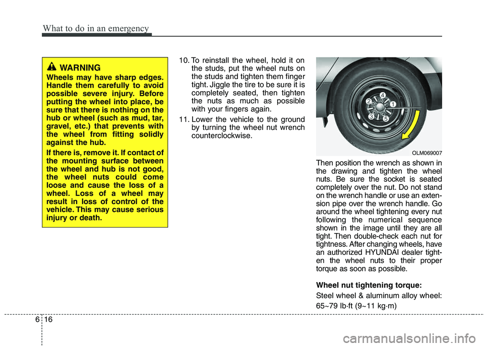
Then position the wrench as shown in
the drawing and tighten the wheel
nuts. Be sure the socket is seated
completely over the nut. Do not stand
on the wrench handle or use an exten-
sion pipe over the wrench handle. Go
around the wheel tightening every nut
following the numerical sequence
shown in the image until they are all
tight. Then double-check each nut for
tightness. After changing wheels, have
an authorized HYUNDAI dealer tight-
en the wheel nuts to their proper
torque as soon as possible.
Wheel nut tightening torque:
Steel wheel & aluminum alloy wheel:65~79 lb·ft (9~11 kg·m)
WARNING
Wheels may have sharp edges.
Handle them carefully to avoid
possible severe injury. Before
putting the wheel into place, besure that there is nothing on the
hub or wheel (such as mud, tar,
gravel, etc.) that prevents with
the wheel from fitting solidly
against the hub.
If there is, remove it. If contact of the mounting surface betweenthe wheel and hub is not good,
the wheel nuts could comeloose and cause the loss of a
wheel. Loss of a wheel may
result in loss of control of the
vehicle. This may cause serious
injury or death.
OLM069007
Page 346 of 397
Maintenance
46
7
Temperature -A, B & C
The temperature grades are A (the highest), B and C representing the
tire’s resistance to the generation ofheat and its ability to dissipate heatwhen tested under controlled condi-
tions on a specified indoor laboratorytest wheel.
Sustained high temperature can
cause the material of the tire to
degenerate and reduce tire life, and
excessive temperature can lead to
sudden tire failure. The grade C cor-
responds to a level of performance
which all passenger car tires must
meet under the Federal Motor
Vehicle Safety Standard No. 109.
Grades B and A represent higher
levels of performance on the labora-
tory test wheel than the minimum
required by law. Tire terminology and definitions Air Pressure
: The amount of air
inside the tire pressing outward on
the tire. Air pressure is expressed inpounds per square inch (psi) or kilo-
pascal (kPa).
Accessory Weight : This means the
combined weight of optional acces-
sories. Some examples of optional
accessories are, automatic transaxle,
power seats, and air conditioning. Aspect Ratio : The relationship of a
tire's height to its width.Belt: A rubber coated layer of cords
that is located between the plies and
the tread. Cords may be made from
steel or other reinforcing materials. Bead : The tire bead contains steel
wires wrapped by steel cords that
hold the tire onto the rim.
Bias Ply Tire : A pneumatic tire in
which the plies are laid at alternate
angles less than 90 degrees to the
centerline of the tread.WARNING - Tire temperature
The temperature grade for this
tire is established for a tire that
is properly inflated and not
overloaded. Excessive speed,
underinflation, or excessive
loading, either separately or in
combination, can cause heat
build-up and possible sudden
tire failure. This can cause loss
of vehicle control and serious
injury or death.
Page 347 of 397
747
Maintenance
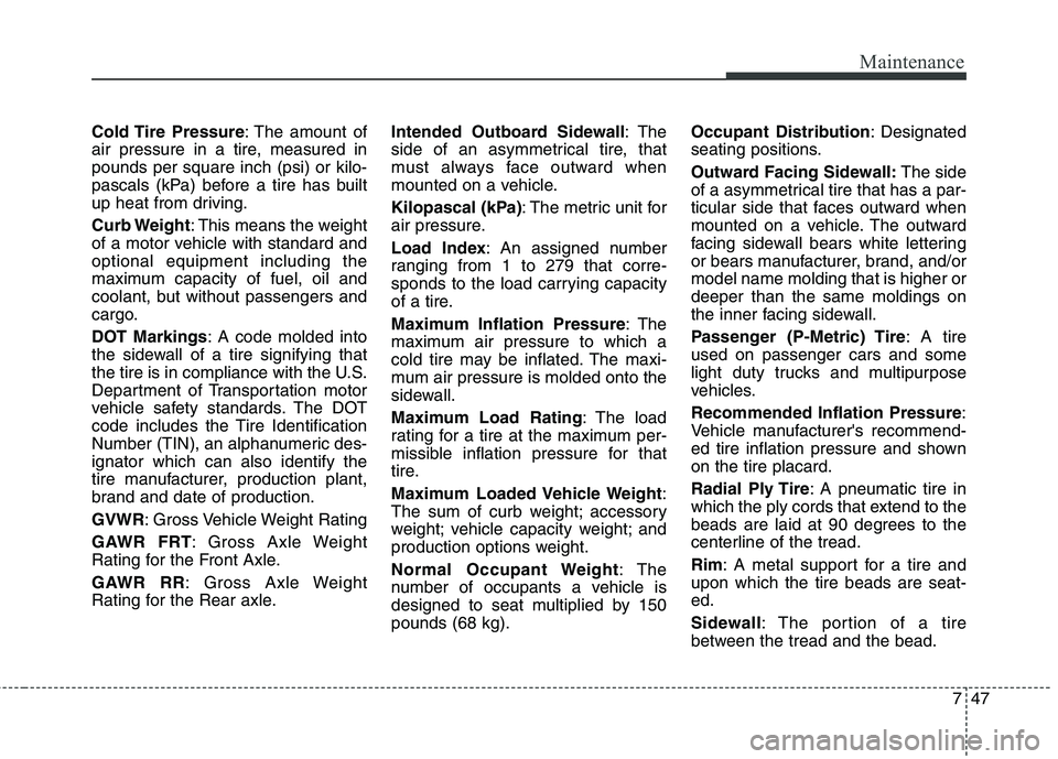
Cold Tire Pressure: The amount of
air pressure in a tire, measured in pounds per square inch (psi) or kilo-
pascals (kPa) before a tire has built
up heat from driving.
Curb Weight : This means the weight
of a motor vehicle with standard and optional equipment including the
maximum capacity of fuel, oil and
coolant, but without passengers and
cargo.
DOT Markings : A code molded into
the sidewall of a tire signifying that
the tire is in compliance with the U.S.
Department of Transportation motor
vehicle safety standards. The DOT
code includes the Tire Identification
Number (TIN), an alphanumeric des-ignator which can also identify the
tire manufacturer, production plant,
brand and date of production. GVWR : Gross Vehicle Weight Rating
GAWR FRT : Gross Axle Weight
Rating for the Front Axle.
GAWR RR : Gross Axle Weight
Rating for the Rear axle. Intended Outboard Sidewall
: The
side of an asymmetrical tire, that
must always face outward when
mounted on a vehicle.
Kilopascal (kPa) : The metric unit for
air pressure.
Load Index : An assigned number
ranging from 1 to 279 that corre-
sponds to the load carrying capacity
of a tire.
Maximum Inflation Pressure : The
maximum air pressure to which a
cold tire may be inflated. The maxi-
mum air pressure is molded onto the
sidewall.
Maximum Load Rating : The load
rating for a tire at the maximum per-
missible inflation pressure for that
tire.
Maximum Loaded Vehicle Weight :
The sum of curb weight; accessory
weight; vehicle capacity weight; and
production options weight.
Normal Occupant Weight :The
number of occupants a vehicle is
designed to seat multiplied by 150pounds (68 kg). Occupant Distribution
: Designated
seating positions.
Outward Facing Sidewall: The side
of a asymmetrical tire that has a par-
ticular side that faces outward when
mounted on a vehicle. The outward
facing sidewall bears white lettering
or bears manufacturer, brand, and/ormodel name molding that is higher ordeeper than the same moldings on
the inner facing sidewall.
Passenger (P-Metric) Tire : A tire
used on passenger cars and some
light duty trucks and multipurpose
vehicles. Recommended Inflation Pressure :
Vehicle manufacturer's recommend-
ed tire inflation pressure and shownon the tire placard.
Radial Ply Tire : A pneumatic tire in
which the ply cords that extend to the
beads are laid at 90 degrees to the
centerline of the tread. Rim : A metal support for a tire and
upon which the tire beads are seat- ed.
Sidewall : The portion of a tire
between the tread and the bead.
Page 348 of 397
Maintenance
48
7
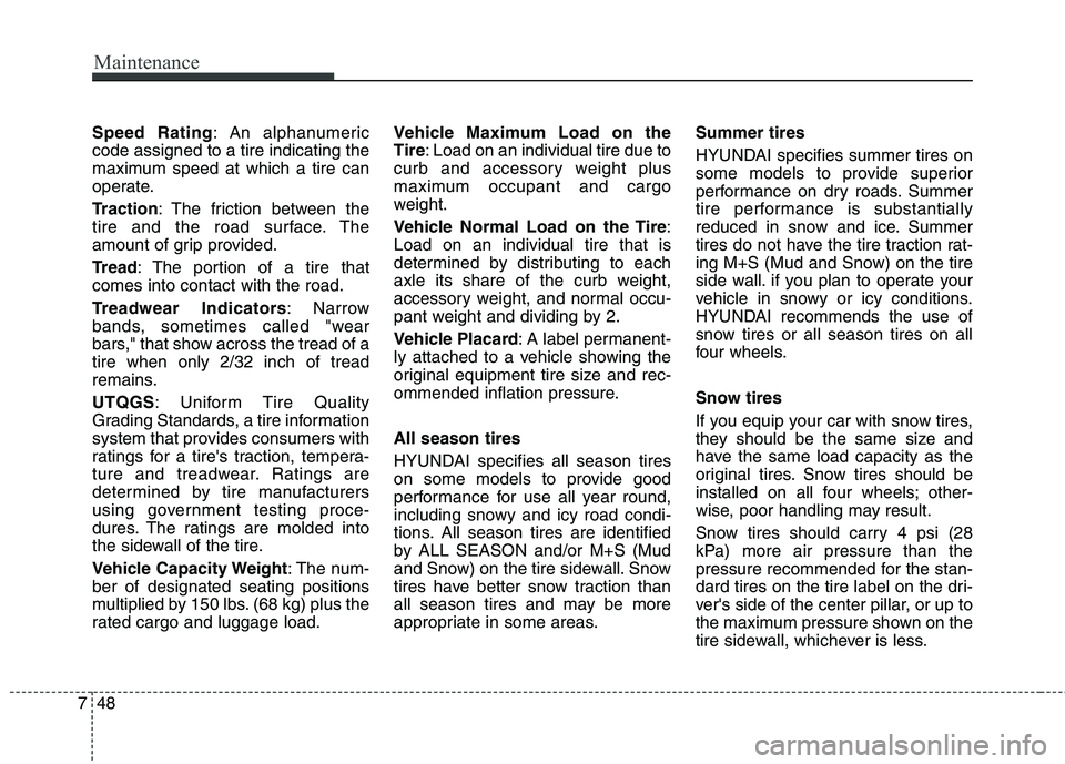
Speed Rating : An alphanumeric
code assigned to a tire indicating the
maximum speed at which a tire can
operate.
Traction : The friction between the
tire and the road surface. The
amount of grip provided.
Tr e a d : The portion of a tire that
comes into contact with the road.
Treadwear Indicators : Narrow
bands, sometimes called "wear
bars," that show across the tread of atire when only 2/32 inch of tread
remains. UTQGS : Uniform Tire Quality
Grading Standards, a tire information
system that provides consumers with
ratings for a tire's traction, tempera-
ture and treadwear. Ratings are
determined by tire manufacturers
using government testing proce-
dures. The ratings are molded into
the sidewall of the tire.
Vehicle Capacity Weight : The num-
ber of designated seating positions
multiplied by 150 lbs. (68 kg) plus the
rated cargo and luggage load. Vehicle Maximum Load on theTire
: Load on an individual tire due to
curb and accessory weight plus
maximum occupant and cargo
weight.
Vehicle Normal Load on the Tire :
Load on an individual tire that is
determined by distributing to each
axle its share of the curb weight,
accessory weight, and normal occu-
pant weight and dividing by 2.
Vehicle Placard : A label permanent-
ly attached to a vehicle showing the
original equipment tire size and rec-
ommended inflation pressure. All season tires
HYUNDAI specifies all season tires
on some models to provide good
performance for use all year round,
including snowy and icy road condi-
tions. All season tires are identified
by ALL SEASON and/or M+S (Mud
and Snow) on the tire sidewall. Snow
tires have better snow traction than
all season tires and may be more
appropriate in some areas. Summer tires
HYUNDAI specifies summer tires on
some models to provide superior
performance on dry roads. Summer
tire performance is substantially
reduced in snow and ice. Summer
tires do not have the tire traction rat-
ing M+S (Mud and Snow) on the tire
side wall. if you plan to operate your
vehicle in snowy or icy conditions.
HYUNDAI recommends the use of
snow tires or all season tires on all
four wheels.
Snow tires
If you equip your car with snow tires,
they should be the same size and
have the same load capacity as the
original tires. Snow tires should be
installed on all four wheels; other-
wise, poor handling may result.
Snow tires should carry 4 psi (28
kPa) more air pressure than the
pressure recommended for the stan-
dard tires on the tire label on the dri-
ver's side of the center pillar, or up to
the maximum pressure shown on the
tire sidewall, whichever is less.
Page 356 of 397
Maintenance
56
7
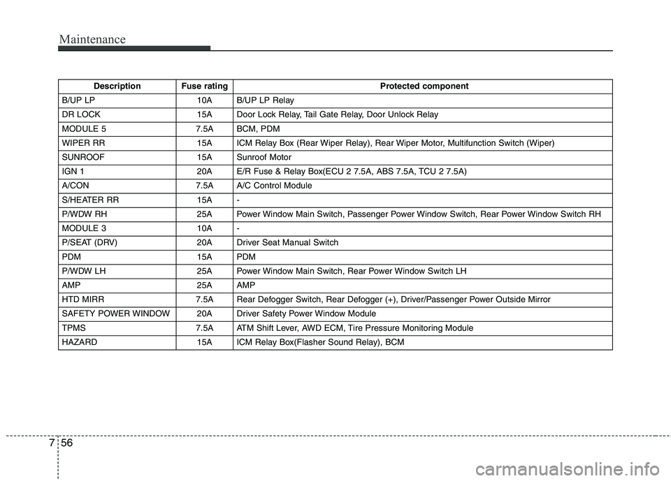
Description Fuse rating Protected component
B/UP LP 10A B/UP LP Relay
DR LOCK 15A Door Lock Relay, Tail Gate Relay, Door Unlock Relay
MODULE 5 7.5A BCM, PDM
WIPER RR 15A ICM Relay Box (Rear Wiper Relay), Rear Wiper Motor, Multifunction Switch (Wiper)
SUNROOF 15A Sunroof Motor
IGN 1 20A E/R Fuse & Relay Box(ECU 2 7.5A, ABS 7.5A, TCU 2 7.5A)
A/CON 7.5A A/C Control Module
S/HEATER RR 15A -
P/WDW RH 25A Power Window Main Switch, Passenger Power Window Switch, Rear Power Window Switch RH
MODULE 3 10A -
P/SEAT (DRV) 20A Driver Seat Manual Switch
PDM 15A PDM
P/WDW LH 25A Power Window Main Switch, Rear Power Window Switch LH
AMP 25A AMP
HTD MIRR 7.5A Rear Defogger Switch, Rear Defogger (+), Driver/Passenger Power Outside Mirror
SAFETY POWER WINDOW 20A Driver Safety Power Window Module
TPMS 7.5A ATM Shift Lever, AWD ECM, Tire Pressure Monitoring Module
HAZARD 15A ICM Relay Box(Flasher Sound Relay), BCM