instrument cluster HYUNDAI TUCSON HYBRID 2022 Workshop Manual
[x] Cancel search | Manufacturer: HYUNDAI, Model Year: 2022, Model line: TUCSON HYBRID, Model: HYUNDAI TUCSON HYBRID 2022Pages: 630, PDF Size: 77.98 MB
Page 420 of 630
07
7-61
Information
• If speed limit information of the road
cannot be recognized, '---' sign will be
displayed. Please refer to "Limitations
of Intelligent Speed Limit Assist " if the
road signs are difficult to recognize.
• Intelligent Speed Limit Assist provides
additional road sign information in
addition to speed limit. The additional
road sign information provided may
vary according to your country.
• Supplementary sign displayed under
the speed limit or overtaking restriction
sign means the conditions under
which the signs must be followed. If
supplementary sign is not recognized, it
will be displayed as blank.
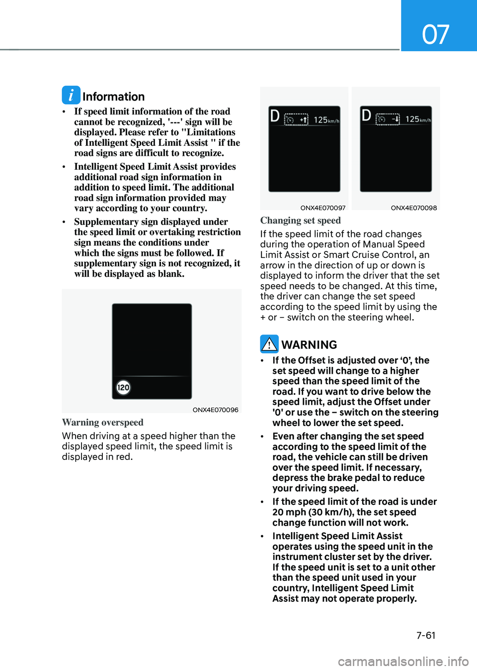
ONX4E070096
Warning overspeed
When driving at a speed higher than the
displayed speed limit, the speed limit is
displayed in red.
ONX4E070097ONX4E070098
Changing set speed
If the speed limit of the road changes
during the operation of Manual Speed
Limit Assist or Smart Cruise Control, an
arrow in the direction of up or down is
displayed to inform the driver that the set
speed needs to be changed. At this time,
the driver can change the set speed
according to the speed limit by using the
+ or – switch on the steering wheel.
WARNING
• If the Offset is adjusted over ‘0’, the
set speed will change to a higher
speed than the speed limit of the
road. If you want to drive below the
speed limit, adjust the Offset under
'0' or use the – switch on the steering
wheel to lower the set speed.
• Even after changing the set speed
according to the speed limit of the
road, the vehicle can still be driven
over the speed limit. If necessary,
depress the brake pedal to reduce
your driving speed.
• If the speed limit of the road is under
20 mph (30 km/h), the set speed
change function will not work.
• Intelligent Speed Limit Assist
operates using the speed unit in the
instrument cluster set by the driver.
If the speed unit is set to a unit other
than the speed unit used in your
country, Intelligent Speed Limit
Assist may not operate properly.
Page 425 of 630
Driver assistance system
7-66
• The driver’s attention lev el is display ed on the scale of 1 t
o 5. The lower the
level is, the more inattentive the driver
is.
• The level decreases when the driver
does not take a break for a certain
period of time.
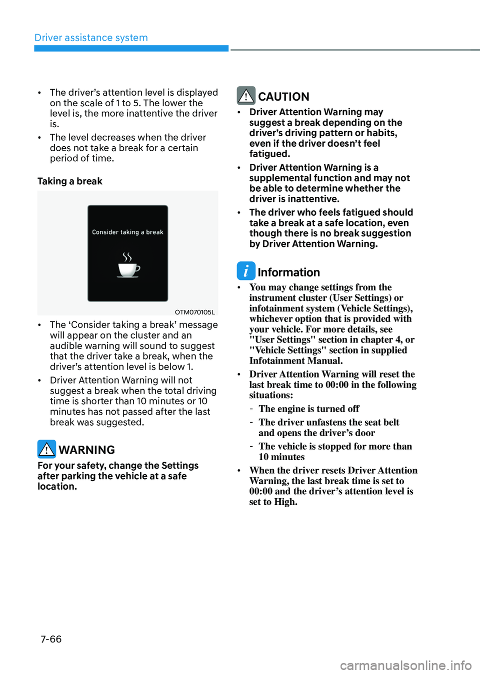
Taking a break
OTM070105L
• The ‘Consider taking a br eak’ message will appear on the clust
er and an
audible warning will sound to suggest
that the driver take a break, when the
driver’s
a
ttention
le
vel
is belo
w
1.
• Driver A
ttention Warning will not
suggest a break when the total driving
time is shorter than 10 minutes or 10
minutes has not passed after the last
break was suggested.
WARNING
For your safety, change the Settings
after parking the vehicle at a safe
location.
CAUTION
• Driver Attention Warning may
suggest a break depending on the
driver’s driving pattern or habits,
even if the driver doesn’t feel
fatigued.
• Driver Attention Warning is a
supplemental function and may not
be able to determine whether the
driver is inattentive.
• The driver who feels fatigued should
take a break at a safe location, even
though there is no break suggestion
by Driver Attention Warning.
Information
• You may change settings from the
instrument cluster (User Settings) or
infotainment system (Vehicle Settings),
whichever option that is provided with
your vehicle. For more details, see
"User Settings" section in chapter 4, or
"Vehicle Settings" section in supplied
Infotainment Manual.
• Driver Attention Warning will reset the
last break time to 00:00 in the following
situations:
-The engine is turned off
-The driver unfastens the seat belt
and opens the driver
’s door
-The vehicle is stopped for mor
e than
10 minutes
• When the driver resets Driver Attention
Warning, the last break time is set to
00:00 and the driver’s attention level is
set to High.
Page 430 of 630
07
7-7 1
Blind-Spot View Monitor
Operating conditions
When the left or right side turn signal
turns on, the image in that direction is
displayed on the instrument cluster.
Off conditions
• When the turn signal turns off, the
image on the instrument cluster will
turn off.
• When the hazard warning flasher
is on, Blind-Spot View Monitor will
turn off, regardless of the turn signal
status.
• When other important warning is
displayed on the instrument cluster,
Blind-Spot View Monitor may turn off.
Blind-Spot View Monitor
Malfunction
When Blind-Spot View Monitor is not
working properly, or the cluster display
flickers, or the camera image does
not display normally, have the vehicle
inspected by an authorized HYUNDAI
dealer.
WARNING
• The image shown on the cluster may
differ from the actual distance of the
object. Make sure to directly check
the vehicle's surroundings for safety.
• Always keep the camera lens clean.
If the lens is covered with foreign
material, it may adversely affect
camera performance and Blind-
Spot View Monitor may not operate
normally.
Page 462 of 630
07
7-103
Information
• You may change settings from the
instrument cluster (User Settings) or
infotainment system (Vehicle Settings),
whichever option that is provided with
your vehicle. For more details, see
"User Settings" section in chapter 4, or
"Vehicle Settings" section in supplied
Infotainment Manual.
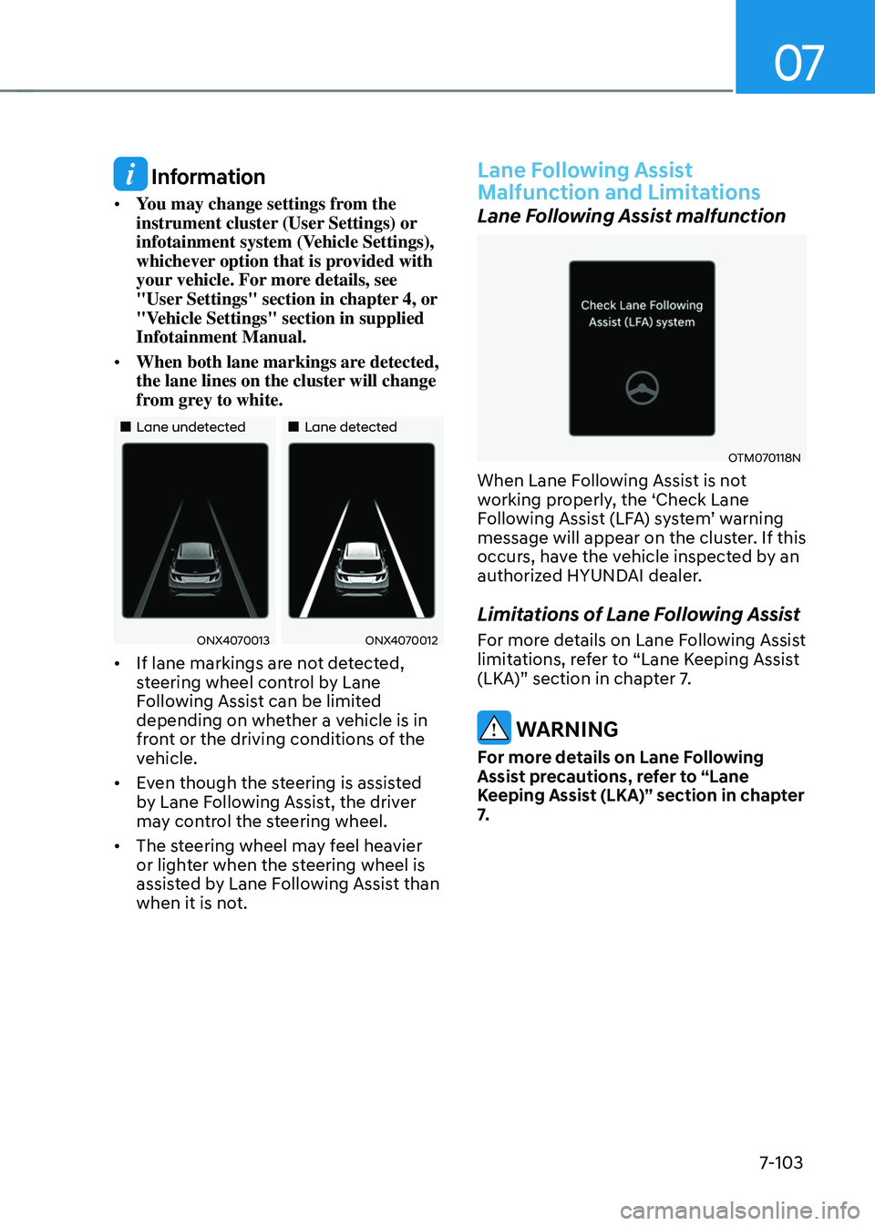
• When both lane markings are detected,
the lane lines on the cluster will change
from grey to white.
„„Lane undetected „„Lane detected
ONX4070013ONX4070012
• If lane markings are not detected,
steering wheel control by Lane
Following Assist can be limited
depending on whether a vehicle is in
front or the driving conditions of the
vehicle.
• Even though the steering is assisted
by Lane Following Assist, the driver
may control the steering wheel.
• The steering wheel may feel heavier
or lighter when the steering wheel is
assisted by Lane Following Assist than
when it is not.
Lane Following Assist
Malfunction and Limitations
Lane Following Assist malfunction
OTM070118N
When Lane Following Assist is not
working properly, the ‘Check Lane
Following
Assis
t
(LF
A)
s
ystem’
w
arning
message will appear on the clust
er. If this
occurs, have the vehicle inspected by an
authorized HYUNDAI dealer.
Limitations of Lane Following Assist
For more details on Lane Following Assist
limitations, refer to “Lane Keeping Assist
(LKA)” section in chapter 7.
WARNING
For more details on Lane Following
Assist precautions, refer to “Lane
Keeping Assist (LKA)” section in chapter
7.
Page 501 of 630
Driver assistance system
7-142
Reverse Parking Collision-
Avoidance Assist Operation
Operating conditions
If ‘Rear Active Assist’ or ‘Rear Warning Only’ is set fr om the Se ttings menu, Re
verse Parking Collision-Avoidance
Assist will be in the ready status when
the following conditions are satisfied:
- The liftga
te is closed
- The gear is shifted t
o R (Reverse)
- Vehicle speed is belo
w 6 mph (10
km/h)
- Re
verse Parking Collision-Avoidance
Assist components such as the rear
view camera and the rear ultrasonic
sensors are in normal conditions
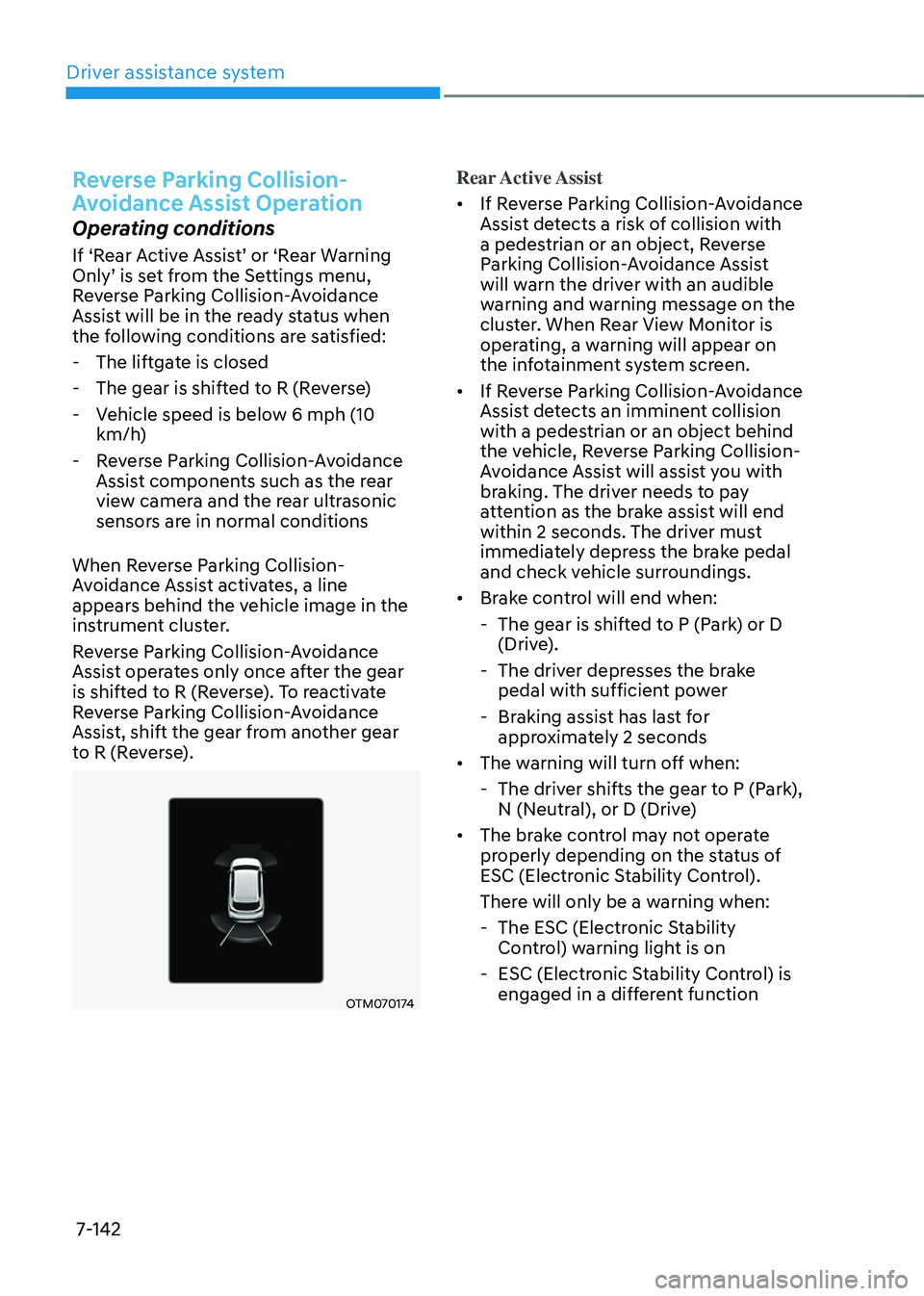
When Reverse Parking Collision-
Avoidance Assist activates, a line
appears behind the vehicle image in the
instrument cluster.
Reverse Parking Collision-Avoidance
Assist operates only once after the gear
is shifted to R (Reverse). To reactivate
Reverse Parking Collision-Avoidance
Assist, shift the gear from another gear
to R (Reverse).
OTM070174
Rear Active Assist
• If Reverse Parking Collision-Avoidance
Assist detects a risk of collision with
a pedestrian or an object, Reverse
Parking Collision-Avoidance Assist
will warn the driver with an audible
warning and warning message on the
cluster. When Rear View Monitor is
operating, a warning will appear on
the infotainment system screen.
• If Reverse Parking Collision-Avoidance
Assist detects an imminent collision
with a pedestrian or an object behind
the vehicle, Reverse Parking Collision-
Avoidance Assist will assist you with
braking. The driver needs to pay
attention as the brake assist will end
within 2 seconds. The driver must
immediately depress the brake pedal
and check vehicle surroundings.
• Brake control will end when:
- The gear is shifted t
o P (Park) or D
(Drive).
- The driver depr
esses the brake
pedal with sufficient power
- Braking assis
t has last for
approximately 2 seconds
• The warning will turn off when:
- The driver shifts the gear t
o P (Park),
N (Neutral), or D (Drive)
• The brake control may not operate
properly depending on the status of
ESC (Electronic Stability Control).
There will only be a warning when:
- The ESC (Electronic S
tability
Control) warning light is on
- ESC (Electronic S
tability Control) is
engaged in a different function
Page 528 of 630
Emergency situations8-8
if tHe engine overHea ts
If your temperature gauge indicates
overheating, you experience a loss of
power, or hear loud pinging or knocking,
the engine may be overheating. If this
happens, you should:
1.
Pull off the r
oad and stop as soon as it
is safe to do so.
2.
Shift the gear to P (P
ark) and set the
parking brake
3.
Turn o
ff the air conditioner.
4.
When the coolant or ho
t steams
gush out of the reservoir, stop the
engine and we recommend that
you call an authorized HYUNDAI
dealer for assistance. If the coolant
does not flow out, leave the engine
compartment opened, while running
the engine. Check the coolant
temperature gauge on the instrument
cluster and turn off the engine to
make sure the coolant temperature is
sufficiently cooled down. 5. Cool down the engine sufficien
tly
and check the coolant level. When it
is insufficient, check its connection
with the radiator, the heater hose,
and the water pump for any leakage.
When there is no leakage, add the
coolant. However, if the problems
persists, such as the coolant leakages,
the cooling-fan malfunction or the
water pump drive belt damages,
immediately stop the engine, and
have your vehicle checked by an
authorized HYUNDAI dealer.
• You should mix antifreeze and water in
a proper ratio to make coolant. If the
antifreeze ratio is too high or low, it
may cause overheating due to the lack
of cooling function.
(Refer to the Mix Ratio in “Checking
the coolant level” in chapter 8.)
• If overheating happens repeatedly,
we recommend that you have
your vehicle to be checked by an
authorized HYUNDAI dealer.
WARNING
While the engine is running,
keep hands, clothing and tools
away from the moving parts
such as the cooling fan and
drive belt to prevent serious
injury.
Page 591 of 630
Maintenance
9-44
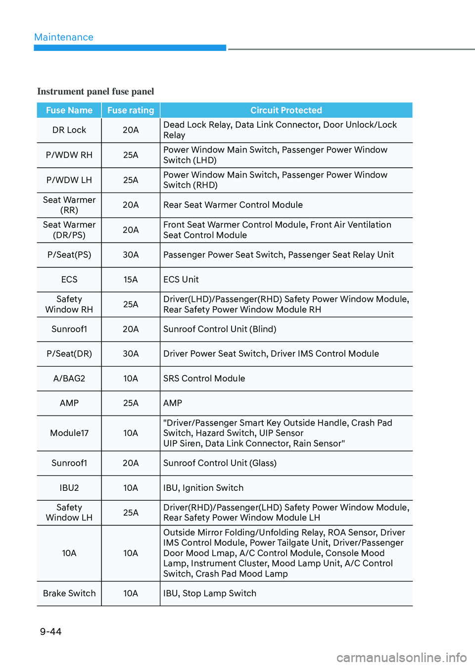
Instrument panel fuse panel
Fuse Name Fuse ratingCircuit Protected
DR Lock 20ADead Lock Relay, Data Link Connector, Door Unlock/Lock
Relay
P/WDW RH 25A Power Window Main Switch, Passenger Power Window
Switch (LHD)
P/WDW LH 25A Power Window Main Switch, Passenger Power Window
Switch (RHD)
Seat Warmer (RR) 20A
Rear Seat Warmer Control Module
Seat Warmer (DR/PS) 20AFront Seat Warmer Control Module, Front Air Ventilation
Seat Control Module
P/Seat(PS) 30APassenger Power Seat Switch, Passenger Seat Relay Unit
ECS 15A ECS Unit
Safety
Window RH 25ADriver(LHD)/Passenger(RHD) Safety Power Window Module,
Rear Safety Power Window Module RH
Sunroof1 20ASunroof Control Unit (Blind)
P/Seat(DR) 30ADriver Power Seat Switch, Driver IMS Control Module
A/BAG2 10ASRS Control Module
AMP 25A AMP
Module17 10A"Driver/Passenger Smart Key Outside Handle, Crash Pad
Switch, Hazard Switch, UIP Sensor
UIP Siren, Data Link Connector, Rain Sensor"
Sunroof1 20ASunroof Control Unit (Glass)
IBU2 10AIBU, Ignition Switch
Safety
Window LH 25ADriver(RHD)/Passenger(LHD) Safety Power Window Module,
Rear Safety Power Window Module LH
10A 10AOutside Mirror Folding/Unfolding Relay, ROA Sensor, Driver
IMS Control Module, Power Tailgate Unit, Driver/Passenger
Door Mood Lmap, A/C Control Module, Console Mood
Lamp, Instrument Cluster, Mood Lamp Unit, A/C Control
Switch, Crash Pad Mood Lamp
Brake Switch 10AIBU, Stop Lamp Switch
Page 592 of 630
09
9-45
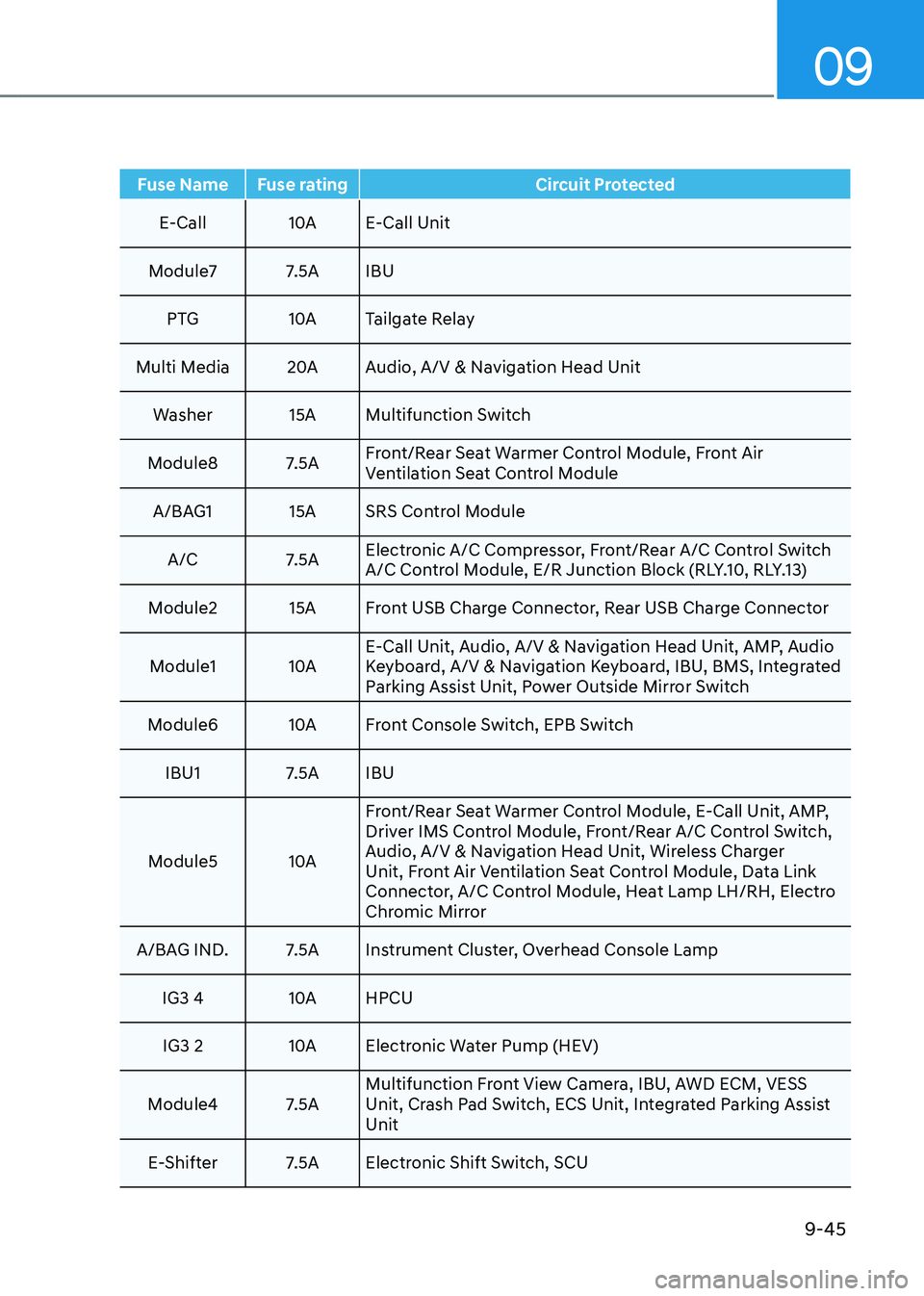
Fuse Name Fuse ratingCircuit Protected
E-Call 10AE-Call Unit
Module7 7.5A IBU PTG 10ATailgate Relay
Multi Media 20AAudio, A/V & Navigation Head Unit
Washer 15A Multifunction Switch
Module8 7.5A Front/Rear Seat Warmer Control Module, Front Air
Ventilation Seat Control Module
A/BAG1 15A SRS Control Module
A/C 7.5A Electronic A/C Compressor, Front/Rear A/C Control Switch
A/C Control Module, E/R Junction Block (RLY.10, RLY.13)
Module2 15A Front USB Charge Connector, Rear USB Charge Connector
Module1 10AE-Call Unit, Audio, A/V & Navigation Head Unit, AMP, Audio
Keyboard, A/V & Navigation Keyboard, IBU, BMS, Integrated
Parking Assist Unit, Power Outside Mirror Switch
Module6 10AFront Console Switch, EPB Switch
IBU1 7.5A IBU
Module5 10AFront/Rear Seat Warmer Control Module, E-Call Unit, AMP,
Driver IMS Control Module, Front/Rear A/C Control Switch,
Audio, A/V & Navigation Head Unit, Wireless Charger
Unit, Front Air Ventilation Seat Control Module, Data Link
Connector, A/C Control Module, Heat Lamp LH/RH, Electro
Chromic Mirror
A/BAG IND. 7.5A Instrument Cluster, Overhead Console Lamp
IG3 4 10AHPCU
IG3 2 10AElectronic Water Pump (HEV)
Module4 7.5A Multifunction Front View Camera, IBU, AWD ECM, VESS
Unit, Crash Pad Switch, ECS Unit, Integrated Parking Assist
Unit
E-Shifter 7.5A Electronic Shift Switch, SCU
Page 593 of 630
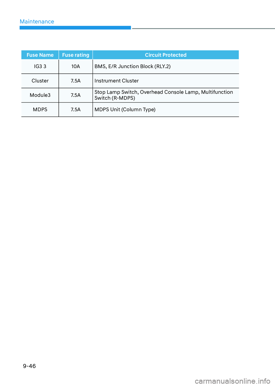
Maintenance
9-46
Fuse Name Fuse ratingCircuit Protected
IG3 3 10ABMS, E/R Junction Block (RLY.2)
Cluster 7.5A Instrument Cluster
Module3 7.5A Stop Lamp Switch, Overhead Console Lamp, Multifunction
Switch (R-MDPS)
MDPS 7.5A MDPS Unit (Column Type)
Page 625 of 630

Index
I-8
Instrument cluster ........................................................................\
..........................4-4
Instrument cluster control ........................................................................\
...........4-5
Gauges and meters ........................................................................\
.....................4-5
Transmission shift indicator ........................................................................\
.......4-9
Warning and indicator lights ........................................................................\
....4-10
LCD display messages ........................................................................\
.............4-22
Instrument panel overview (I)
........................................................................\
......2-5
Instrument panel overview (II)
........................................................................\
.....2-6
Integrated memory system
........................................................................\
...........5-38
Recalling memory positions ........................................................................\
.....5-39
Resetting the system ........................................................................\
.................5-39
Seat Easy Access Operation ........................................................................\
.....5-40
Storing memory positions ........................................................................\
........5-38
Intelligent Speed Limit Assist (ISLA)
.................................................................7-52
System malfunction and limitations .................................................................7-55
System operation ........................................................................\
......................7-53
System settings ........................................................................\
.........................7-52
Interior features
........................................................................\
..........................5-117
Cargo security screen ........................................................................\
.............5-125
Clock ........................................................................\
......................................5-123
Coat hook ........................................................................\
...............................5-123
Cup holder ........................................................................\
..............................5-117
Floor mat anchor(s) ........................................................................\
................5-124
Luggage net holder ........................................................................\
.................5-124
Power outlet ........................................................................\
............................5-118
Sunvisor ........................................................................\
..................................5-118
USB charger ........................................................................\
...........................5-119
Wireless smart phone charging system ..........................................................5-120
Interior lights
........................................................................\
...............................5-88
Front lamps ........................................................................\
...............................5-88
Glove box lamp ........................................................................\
........................5-90
Interior Lamp AUT O OFF ........................................................................\
.......5-88
Luggage compartment lamp ........................................................................\
.....5-90
Rear lamps ........................................................................\
................................5-89
Vanity mirror lamp ........................................................................\
...................5-89
Welcome system ........................................................................\
.......................5-91
Interior overview
........................................................................\
..........................2-4