HYUNDAI VELOSTER 2012 Owners Manual
Manufacturer: HYUNDAI, Model Year: 2012, Model line: VELOSTER, Model: HYUNDAI VELOSTER 2012Pages: 385, PDF Size: 24.4 MB
Page 341 of 385
747
Maintenance
Do not drive faster than 75 mph (120
km/h) when your car is equipped with
snow tires.
Tire chains
Tire chains, if necessary, should be
installed on the front wheels.
Be sure that the chains are installed
in accordance with the manufactur-
er's instructions.
To minimize tire and chain wear, do
not continue to use tire chains when
they are no longer needed.Radial-ply tires
Radial-ply tires provide improved
tread life, road hazard resistance and
smoother high speed ride. The radi-
al-ply tires used on this vehicle are of
belted construction, and are selected
to complement the ride and handling
characteristics of your vehicle.
Radial-ply tires have the same load
carrying capacity, as bias-ply or bias
belted tires of the same size, and use
the same recommended inflation
pressure. Mixing of radial-ply tires
with bias-ply or bias belted tires is
not recommended. Any combina-
tions of radial-ply and bias-ply or bias
belted tires when used on the same
vehicle will seriously deteriorate
vehicle handling. The best rule to fol-
low is: Identical radial-ply tires should
always be used as a set of four.
Longer wearing tires can be more
susceptible to irregular tread wear. It
is very important to follow the tire
rotation interval shown in this section
to achieve the tread life potential of
these tires. Cuts and punctures in
radial-ply tires are repairable only in
the tread area, because of sidewall
flexing. Consult your tire dealer for
radial-ply tire repairs.WARNING- Snow or ice
When driving on roads cov-
ered with snow or ice, drive at
less than 20 mph (30 km/h).
Use the SAE “S” class or wire
chains.
If you hear noise caused by
chains contacting the body,
retighten the chain to avoid
contact with the vehicle body.
To prevent body damage,
retighten the chains after driv-
ing 0.3~0.6 miles (0.5~1.0 km).
Do not use tire chains on
vehicles equipped with alu-
minum wheels. In unavoid-
able circumstance, use a wire
type chain.
Use wire chains less than 0.59
inches (15 mm) to prevent
damage to the chain’s con-
nection.
CAUTION
Since the sidewalls of radial
tires are thinner, they can be
damaged by mounting some
types of snow chains on them.
Therefore, the use of snow tires
is recommended instead of
snow chains.
Page 342 of 385
Maintenance
48 7
FUSES
A vehicle’s electrical system is protected
from electrical overload damage by
fuses.This vehicle has 2 fuse panels, one locat-
ed in the driver’s side panel bolster, the
other in the engine compartment.
If any of your vehicle’s lights, acces-
sories, or controls do not work, check the
appropriate circuit fuse. If a fuse has
blown, the element inside the fuse will be
melted.
If the electrical system does not work,
first check the driver’s side fuse panel.
Always replace a blown fuse with one of
the same rating.
If the replacement fuse blows, this indi-
cates an electrical problem. Avoid using
the system involved and immediately
consult an authorized HYUNDAI dealer.
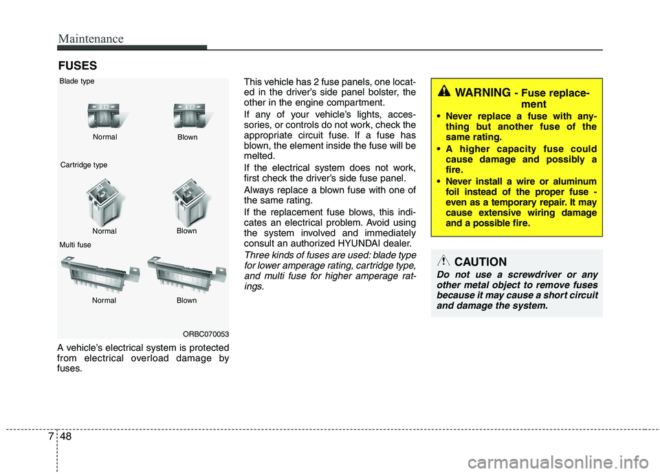
Three kinds of fuses are used: blade type
for lower amperage rating, cartridge type,
and multi fuse for higher amperage rat-
ings.
WARNING - Fuse replace-
ment
Never replace a fuse with any-
thing but another fuse of the
same rating.
A higher capacity fuse could
cause damage and possibly a
fire.
Never install a wire or aluminum
foil instead of the proper fuse -
even as a temporary repair. It may
cause extensive wiring damage
and a possible fire.
CAUTION
Do not use a screwdriver or any
other metal object to remove fuses
because it may cause a short circuit
and damage the system.
ORBC070053 NormalNormal Blade type
Cartridge type
Multi fuseBlown
Blown
Normal Blown
Page 343 of 385
749
Maintenance
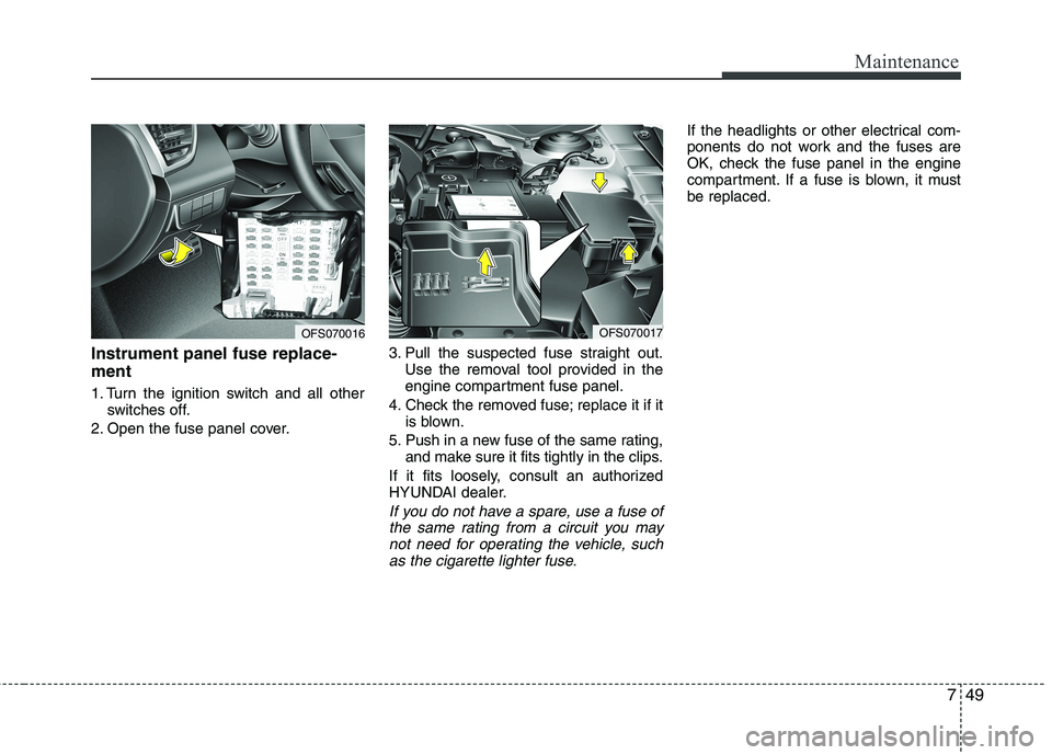
Instrument panel fuse replace-
ment
1. Turn the ignition switch and all other
switches off.
2. Open the fuse panel cover.3. Pull the suspected fuse straight out.
Use the removal tool provided in the
engine compartment fuse panel.
4. Check the removed fuse; replace it if it
is blown.
5. Push in a new fuse of the same rating,
and make sure it fits tightly in the clips.
If it fits loosely, consult an authorized
HYUNDAI dealer.
If you do not have a spare, use a fuse of
the same rating from a circuit you may
not need for operating the vehicle, such
as the cigarette lighter fuse.
If the headlights or other electrical com-
ponents do not work and the fuses are
OK, check the fuse panel in the engine
compartment. If a fuse is blown, it must
be replaced.
OFS070016OFS070017
Page 344 of 385
Maintenance
50 7
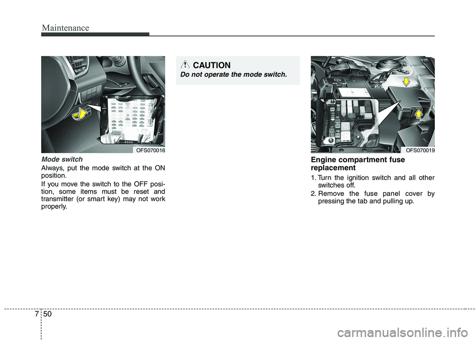
Mode switch
Always, put the mode switch at the ON
position.
If you move the switch to the OFF posi-
tion, some items must be reset and
transmitter (or smart key) may not work
properly.
Engine compartment fuse
replacement
1. Turn the ignition switch and all other
switches off.
2. Remove the fuse panel cover by
pressing the tab and pulling up.
OFS070016OFS070019
CAUTION
Do not operate the mode switch.
Page 345 of 385
751
Maintenance
3. Check the removed fuse; replace it if it
is blown. To remove or insert the fuse,
use the fuse puller in the engine com-
partment fuse panel.
4. Push in a new fuse of the same rating,
and make sure it fits tightly in the clips.
If it fits loosely, consult an authorized
HYUNDAI dealer.
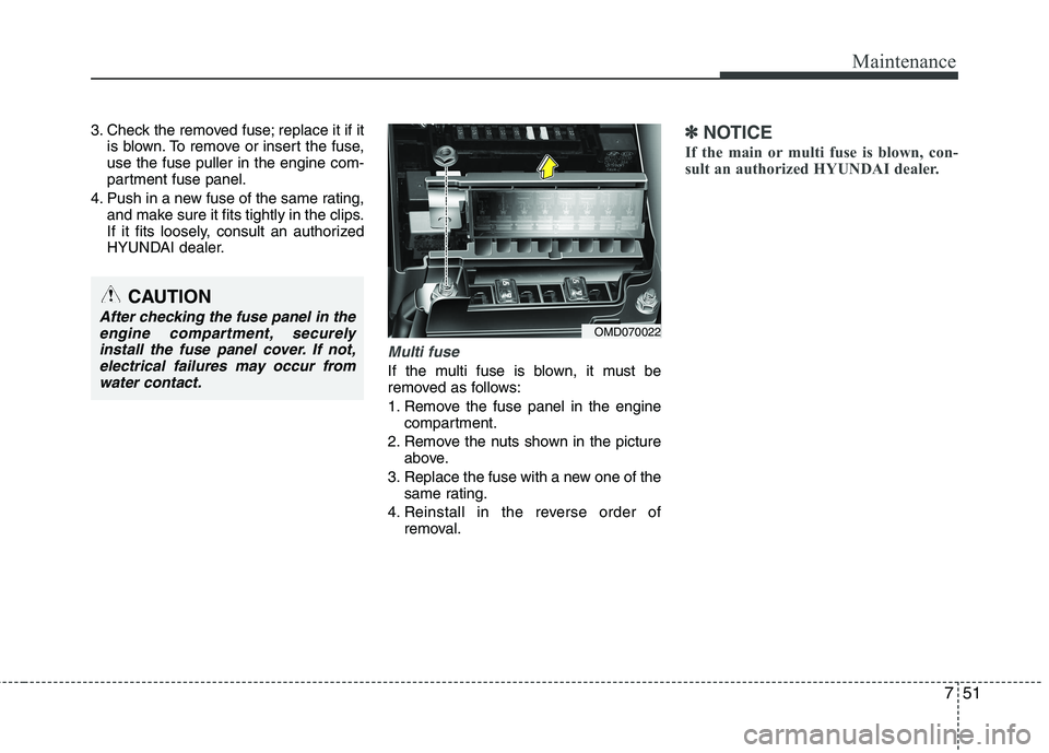
Multi fuse
If the multi fuse is blown, it must be
removed as follows:
1. Remove the fuse panel in the engine
compartment.
2. Remove the nuts shown in the picture
above.
3. Replace the fuse with a new one of the
same rating.
4. Reinstall in the reverse order of
removal.
✽ ✽
NOTICE
If the main or multi fuse is blown, con-
sult an authorized HYUNDAI dealer.
CAUTION
After checking the fuse panel in the
engine compartment, securely
install the fuse panel cover. If not,
electrical failures may occur from
water contact.OMD070022
Page 346 of 385
Maintenance
52 7
✽
✽
NOTICE
Not all fuse panel descriptions in this
manual may be applicable to your vehi-
cle. It is accurate at the time of printing.
When you inspect the fuse panel in your
vehicle, refer to the fuse panel label.
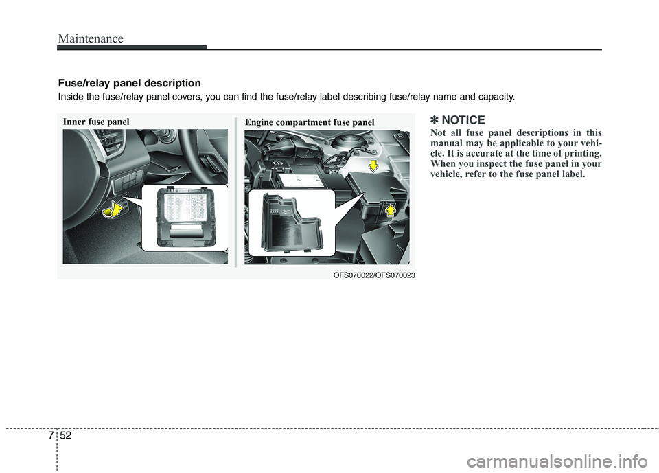
Fuse/relay panel description
Inside the fuse/relay panel covers, you can find the fuse/relay label describing fuse/relay name and capacity.
Inner fuse panel
OFS070022/OFS070023
Engine compartment fuse panel
Page 347 of 385
753
Maintenance
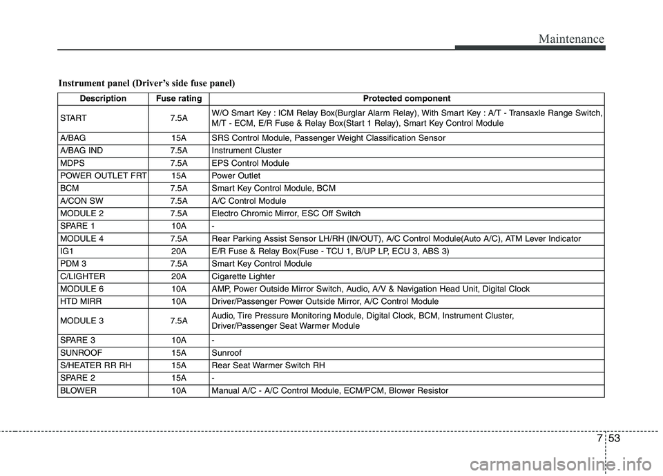
Instrument panel (Driver’s side fuse panel)
Description Fuse rating Protected component
START 7.5AW/O Smart Key : ICM Relay Box(Burglar Alarm Relay), With Smart Key : A/T - Transaxle Range Switch,
M/T - ECM, E/R Fuse & Relay Box(Start 1 Relay), Smart Key Control Module
A/BAG 15A SRS Control Module, Passenger Weight Classification Sensor
A/BAG IND 7.5A Instrument Cluster
MDPS 7.5A EPS Control Module
POWER OUTLET FRT 15A Power Outlet
BCM 7.5A Smart Key Control Module, BCM
A/CON SW 7.5A A/C Control Module
MODULE 2 7.5A Electro Chromic Mirror, ESC Off Switch
SPARE 1 10A -
MODULE 4 7.5A Rear Parking Assist Sensor LH/RH (IN/OUT), A/C Control Module(Auto A/C), ATM Lever Indicator
IG1 20A E/R Fuse & Relay Box(Fuse - TCU 1, B/UP LP, ECU 3, ABS 3)
PDM 3 7.5A Smart Key Control Module
C/LIGHTER 20A Cigarette Lighter
MODULE 6 10A AMP, Power Outside Mirror Switch, Audio, A/V & Navigation Head Unit, Digital Clock
HTD MIRR 10A Driver/Passenger Power Outside Mirror, A/C Control Module
MODULE 3 7.5AAudio, Tire Pressure Monitoring Module, Digital Clock, BCM, Instrument Cluster,
Driver/Passenger Seat Warmer Module
SPARE 3 10A -
SUNROOF 15A Sunroof
S/HEATER RR RH 15A Rear Seat Warmer Switch RH
SPARE 2 15A -
BLOWER 10A Manual A/C - A/C Control Module, ECM/PCM, Blower Resistor
Page 348 of 385
Maintenance
54 7
Description Fuse rating Protected component
I.O.D 1 10ALuggage Lamp, Vanity Lamp LH/RH, Room Lamp, Overhead Console Lamp,
Ignition Key Ill. & Door Warning Switch(W/O Smart Key)
TRUNK 10A Trunk Relay
MODULE 1 7.5A Sport Mode Switch(A/T), Key Solenoid(W/O Smart Key)
SPARE 4 15A -
S/HEATER RR LH 15A Rear Seat Warmer Switch LH
MODULE 7 7.5A Smart Key Control Module, BCM
I.O.D 2 20A Audio, A/V & Navigation Head Unit
P/WDW RH 25A P/WDW RH Relay
PDM 2 7.5A Smart Key Control Module, Start Stop Button Switch
SPARE 6 10A -
WIPER FRT 25AICM Relay Box(Rain Sensor Relay), Multifunction Switch, Wiper Motor,
E/R Fuse & Relay Box(Wiper Relay)
MODULE 5 7.5A Cluster Ionizer(Auto A/C), Rain Sensor, Sunroof
AMP 1 25A AMP
PDM 1 25A Smart Key Control Module
SPARE 5 20A -
A/CON 7.5A A/C Control Module, E/R Fuse & Relay Box(Blower Relay)
I.O.D 4 10ATire Pressure Monitoring Module, BCM, Auto Light & Photo Sensor, Instrument Cluster,
Data Link Connector, Smart Junction Box Upgrade Connector, Electro Chromic Mirror,
A/C Control Module, Digital Clock
P/WDW LH 25A P/WDW LH Relay, Driver Safety Power Window Module
DR LOCK 20A Door Lock Relay, Door Unlock Relay, ICM Relay Box(Two Turn Relay)
P/SEAT DRV 30A Driver Seat Manual Switch
Page 349 of 385
755
Maintenance
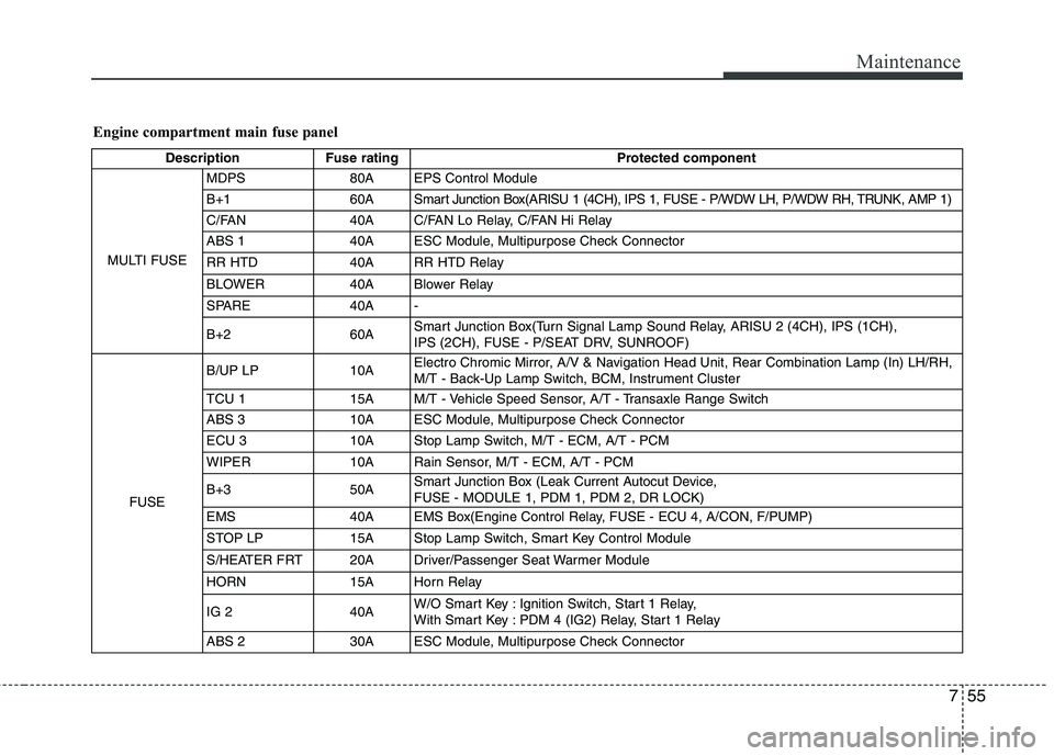
Engine compartment main fuse panel
Description Fuse rating Protected component
MULTI FUSEMDPS 80A EPS Control Module
B+1 60A Smart Junction Box(ARISU 1 (4CH), IPS 1, FUSE - P/WDW LH, P/WDW RH, TRUNK, AMP 1)
C/FAN 40A C/FAN Lo Relay, C/FAN Hi Relay
ABS 1 40A ESC Module, Multipurpose Check Connector
RR HTD 40A RR HTD Relay
BLOWER 40A Blower Relay
SPARE 40A -
B+260ASmart Junction Box(Turn Signal Lamp Sound Relay, ARISU 2 (4CH), IPS (1CH),
IPS (2CH), FUSE - P/SEAT DRV, SUNROOF)
FUSEB/UP LP 10AElectro Chromic Mirror, A/V & Navigation Head Unit, Rear Combination Lamp (In) LH/RH,
M/T - Back-Up Lamp Switch, BCM, Instrument Cluster
TCU 115AM/T - Vehicle Speed Sensor, A/T - Transaxle Range Switch
ABS 3 10A ESC Module, Multipurpose Check Connector
ECU 3 10A Stop Lamp Switch, M/T - ECM, A/T - PCM
WIPER 10A Rain Sensor, M/T - ECM, A/T - PCM
B+3 50ASmart Junction Box (Leak Current Autocut Device,
FUSE - MODULE 1, PDM 1, PDM 2, DR LOCK)
EMS 40A EMS Box(Engine Control Relay, FUSE - ECU 4, A/CON, F/PUMP)
STOP LP 15A Stop Lamp Switch, Smart Key Control Module
S/HEATER FRT 20A Driver/Passenger Seat Warmer Module
HORN 15A Horn Relay
IG 2 40AW/O Smart Key : Ignition Switch, Start 1 Relay,
With Smart Key : PDM 4 (IG2) Relay, Start 1 Relay
ABS 2 30A ESC Module, Multipurpose Check Connector
Page 350 of 385
Maintenance
56 7
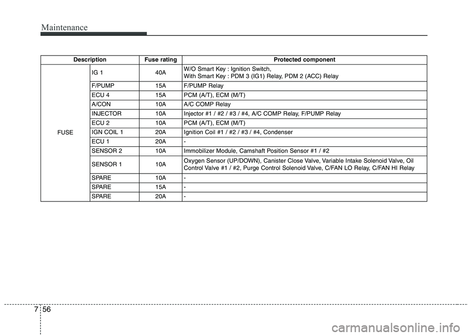
Description Fuse rating Protected component
FUSEIG 1 40AW/O Smart Key : Ignition Switch,
With Smart Key : PDM 3 (IG1) Relay, PDM 2 (ACC) Relay
F/PUMP 15A F/PUMP Relay
ECU 4 15A PCM (A/T), ECM (M/T)
A/CON 10A A/C COMP Relay
INJECTOR 10A Injector #1 / #2 / #3 / #4, A/C COMP Relay, F/PUMP Relay
ECU 2 10A PCM (A/T), ECM (M/T)
IGN COIL 1 20A Ignition Coil #1 / #2 / #3 / #4, Condenser
ECU 1 20A -
SENSOR 2 10A Immobilizer Module, Camshaft Position Sensor #1 / #2
SENSOR 1 10AOxygen Sensor (UP/DOWN), Canister Close Valve, Variable Intake Solenoid Valve, Oil
Control Valve #1 / #2, Purge Control Solenoid Valve, C/FAN LO Relay, C/FAN HI Relay
SPARE 10A -
SPARE 15A -
SPARE 20A -