sensor HYUNDAI VELOSTER 2015 Owner's Manual
[x] Cancel search | Manufacturer: HYUNDAI, Model Year: 2015, Model line: VELOSTER, Model: HYUNDAI VELOSTER 2015Pages: 384, PDF Size: 25 MB
Page 175 of 384
499
Features of your vehicle
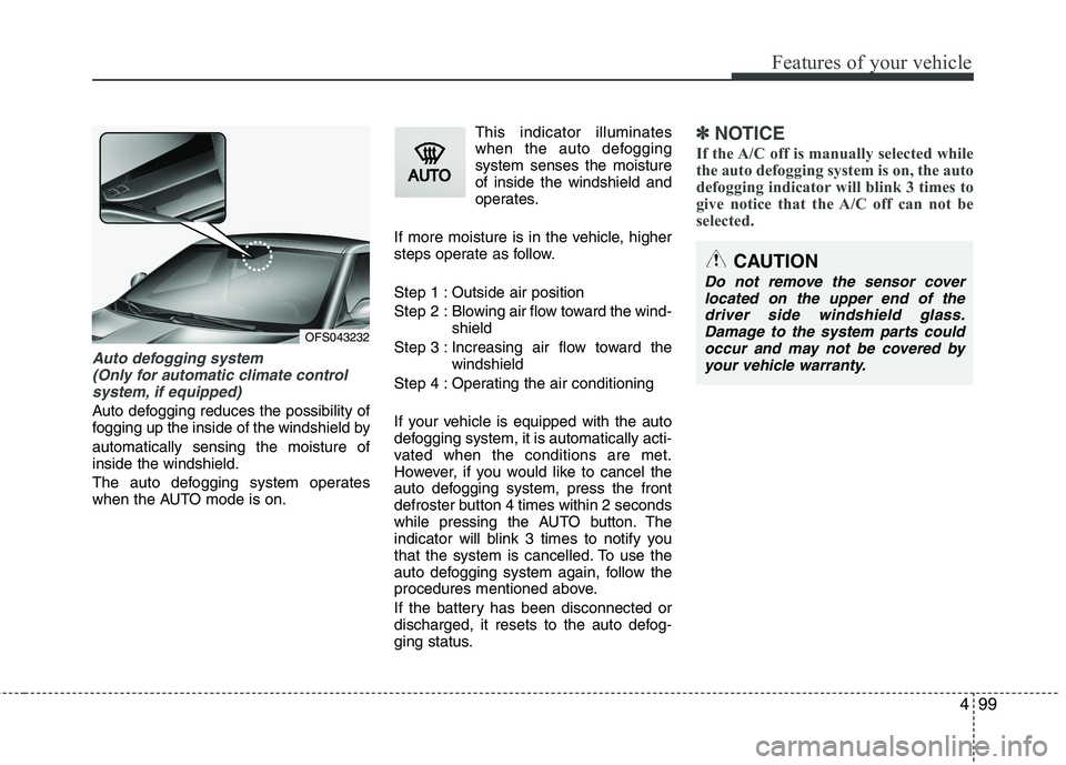
Auto defogging system
(Only for automatic climate control
system, if equipped)
Auto defogging reduces the possibility of
fogging up the inside of the windshield by
automatically sensing the moisture of
inside the windshield.
The auto defogging system operates
when the AUTO mode is on.This indicator illuminates
when the auto defogging
system senses the moisture
of inside the windshield and
operates.
If more moisture is in the vehicle, higher
steps operate as follow.
Step 1 : Outside air position
Step 2 : Blowing air flow toward the wind-
shield
Step 3 : Increasing air flow toward the
windshield
Step 4 : Operating the air conditioning
If your vehicle is equipped with the auto
defogging system, it is automatically acti-
vated when the conditions are met.
However, if you would like to cancel the
auto defogging system, press the front
defroster button 4 times within 2 seconds
while pressing the AUTO button. The
indicator will blink 3 times to notify you
that the system is cancelled. To use the
auto defogging system again, follow the
procedures mentioned above.
If the battery has been disconnected or
discharged, it resets to the auto defog-
ging status.
✽ ✽
NOTICE
If the A/C off is manually selected while
the auto defogging system is on, the auto
defogging indicator will blink 3 times to
give notice that the A/C off can not be
selected.
OFS043232
CAUTION
Do not remove the sensor cover
located on the upper end of the
driver side windshield glass.
Damage to the system parts could
occur and may not be covered by
your vehicle warranty.
Page 256 of 384
What to do in an emergency
10 6
Changing a tire with TPMS
If you have a flat tire, the Low Tire
Pressure will come on. Have the flat
tire repaired by an authorized
HYUNDAI dealer as soon as possi-
ble or replace the flat tire with the
spare tire (if equipped).Each wheel is equipped with a tire
pressure sensor mounted inside the
tire behind the valve stem. You must
use TPMS specific wheels. It is rec-
ommended that you always have
your tires serviced by an authorized
HYUNDAI dealer.
Even if you replace the low pressure
tire with the spare tire, the Low Tire
Pressure Telltale will blink or remain
on until the low pressure tire is
repaired and placed on the vehicle.
After you replace the low pressure
tire with the spare tire (if equipped),
the Low Tire Pressure Telltale may
blink or illuminate after a few minutes
because no TPMS sensor mounted
on the spare wheel.
Once the low pressure tire is reinflat-
ed to the recommended pressure
and installed on the vehicle the
TPMS malfunction indicator and the
low tire pressure telltale will extin-
guish within a few minutes of driving.If the indicator is not extinguished
after a few minutes of driving, please
visit an authorized HYUNDAI dealer.
You may not be able to identify a low
tire by simply looking at it. Always
use a good quality tire pressure
gauge to measure the tire's inflation
pressure. Please note that a tire that
is hot (from being driven) will have a
higher pressure measurement than a
tire that is cold.
A cold tire means the vehicle has
been sitting for 3 hours and driven for
less than 1 mile (1.6 km) in that 3
hour period.
Allow the tire to cool before measur-
ing the inflation pressure. Always be
sure the tire is cold before inflating to
the recommended pressure.
CAUTION
Never use a puncture-repairing
agent not approved by HYUNDAI
to repair and/or inflate a low
pressure tire. The tire sealant not
approved by HYUNDAI may dam-
age the tire pressure sensor.
The sealant on the tire pressure
sensor and wheel shall be elem-
inated when you replace the tire
with a new one.
Page 257 of 384
611
What to do in an emergency
This device complies with Part 15
of the FCC rules.
Operation is subject to the following
two conditions:
1.This device may not cause harmful
interference, and
2.This device must accept any inter-
ference received, including inter-
ference that may cause undesired
operation.CAUTION
Do not use any tire sealant
except the Tire Mobility Kit
approved by HYUNDAI if your
vehicle is equipped with a Tire
Pressure Monitoring System.
The liquid sealant can damage
the tire pressure sensors.
WARNING - Protecting
TPMS
Tampering with, modifying, or
disabling the Tire Pressure
Monitoring System (TPMS) com-
ponents may interfere with the
system's ability to warn the driv-
er of low tire pressure condi-
tions and/or TPMS malfunctions.
Tampering with, modifying, or
disabling the Tire Pressure
Monitoring System (TPMS) com-
ponents may void the warranty
for that portion of the vehicle.
WARNING- TPMS
The TPMS cannot alert you to
severe and sudden tire dam-
age caused by external fac-
tors such as nails or road
debris.
If you feel any vehicle instabil-
ity, immediately take your foot
off the accelerator, apply the
brakes gradually and with
light force, and slowly move to
a safe position off the road.WARNING
Changes or modifications not
expressly approved by the party
responsible for compliance
could void the user’s authority
to operate the equipment.
Page 271 of 384
625
What to do in an emergency
Distributing the sealant
11. Immediately drive approximately
4~6miles (7~10km or, about
10min) to evenly distribute the
sealant in the tire.
Do not exceed a speed of 50 mph
(80 km/h). If possible, do not fall
below a speed of 12 mph (20 km/h).
While driving, if you experience any
unusual vibration, ride disturbance or
noise, reduce your speed and drive
with caution until you can safely pull
off of the side of the road.
Call for road side service or towing.
When you use the Tire Mobility Kit,
the tire pressure sensors and wheel
may be damaged by sealant. Have
the wheel and tire pressure sensors
inspected at an authorized dealer.Checking the tire inflation pres-
sure
1.After driving approximately 4
~6miles(7~10km or about 10min),
stop at a safety location.
2.Connect connection hose (9) of the
compressor directly to the tire
valve.
3.Plug the compressor power cord
into the vehicle power outlet.
4.Adjust the tire inflation pressure to
the recomended tire inflation.
With the ignition switched on, pro-
ceed as follows.
- To increase the inflation pres-
sure :Switch on the compressor,
position I. To check the current
inflation pressure setting, briefly
switch off the compressor.✽ ✽
NOTICE
The pressure gauge may show high-
er than actual reading when the
compressor is running. To get an
accurate tire pressure, the compres-
sor needs to be turned off.
- To reduce the inflation pres-
sure:Press the button (8) on the
compressor.
Page 272 of 384
What to do in an emergency
26 6
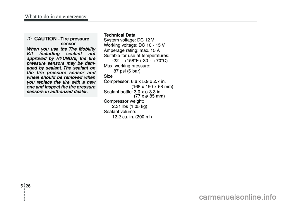
Technical Data
System voltage: DC 12 V
Working voltage: DC 10 - 15 V
Amperage rating: max. 15 A
Suitable for use at temperatures:
-22 ~ +158°F (-30 ~ +70°C)
Max. working pressure:
87 psi (6 bar)
Size
Compressor: 6.6 x 5.9 x 2.7 in.
(168 x 150 x 68 mm)
Sealant bottle: 3.0 x ø 3.3 in.
(77 x ø 85 mm)
Compressor weight:
2.31 lbs (1.05 kg)
Sealant volume:
12.2 cu. in. (200 ml)CAUTION - Tire pressure
sensor
When you use the Tire Mobility
Kit including sealant not
approved by HYUNDAI, the tire
pressure sensors may be dam-
aged by sealant. The sealant on
the tire pressure sensor and
wheel should be removed when
you replace the tire with a new
one and inspect the tire pressure
sensors in authorized dealer.
Page 315 of 384
739
Maintenance
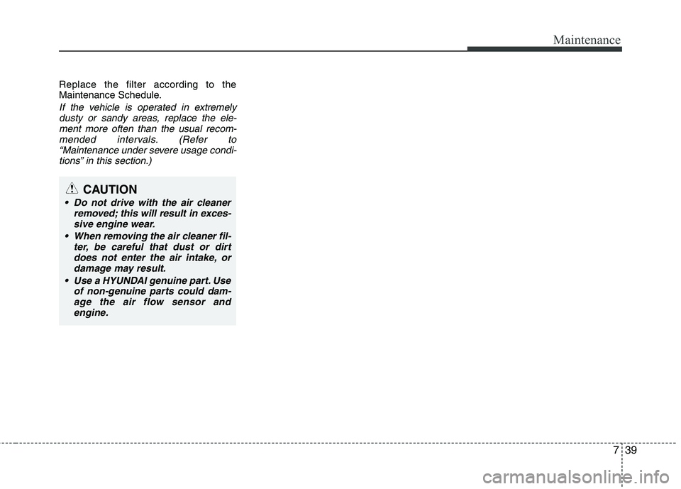
Replace the filter according to the
Maintenance Schedule.
If the vehicle is operated in extremely
dusty or sandy areas, replace the ele-
ment more often than the usual recom-
mended intervals. (Refer to
“Maintenance under severe usage condi-
tions” in this section.)
CAUTION
Do not drive with the air cleaner
removed; this will result in exces-
sive engine wear.
When removing the air cleaner fil-
ter, be careful that dust or dirt
does not enter the air intake, or
damage may result.
Use a HYUNDAI genuine part. Use
of non-genuine parts could dam-
age the air flow sensor and
engine.
Page 344 of 384
Maintenance
68 7
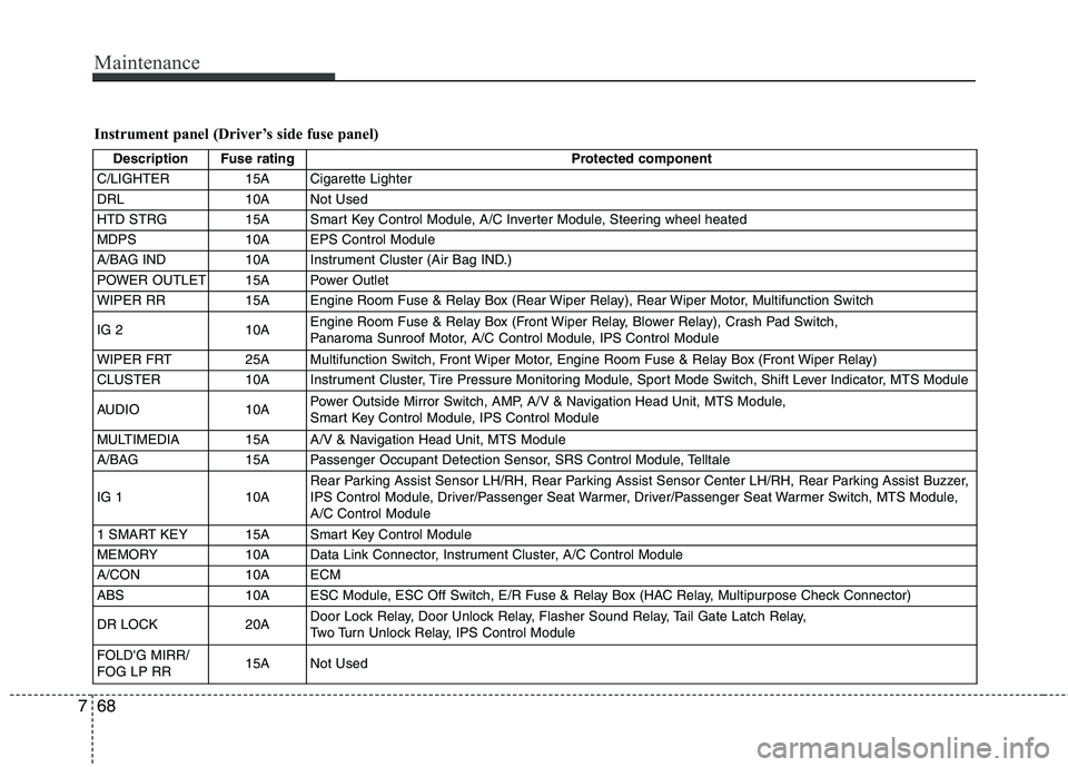
Instrument panel (Driver’s side fuse panel)
Description Fuse rating Protected component
C/LIGHTER 15A Cigarette Lighter
DRL 10A Not Used
HTD STRG 15A Smart Key Control Module, A/C Inverter Module, Steering wheel heated
MDPS 10A EPS Control Module
A/BAG IND 10A Instrument Cluster (Air Bag IND.)
POWER OUTLET 15A Power Outlet
WIPER RR 15A Engine Room Fuse & Relay Box (Rear Wiper Relay), Rear Wiper Motor, Multifunction Switch
IG 2 10AEngine Room Fuse & Relay Box (Front Wiper Relay, Blower Relay), Crash Pad Switch,
Panaroma Sunroof Motor, A/C Control Module, IPS Control Module
WIPER FRT 25A Multifunction Switch, Front Wiper Motor, Engine Room Fuse & Relay Box (Front Wiper Relay)
CLUSTER 10A Instrument Cluster, Tire Pressure Monitoring Module, Sport Mode Switch, Shift Lever Indicator, MTS Module
AUDIO 10APower Outside Mirror Switch, AMP, A/V & Navigation Head Unit, MTS Module,
Smart Key Control Module, IPS Control Module
MULTIMEDIA 15A A/V & Navigation Head Unit, MTS Module
A/BAG 15A Passenger Occupant Detection Sensor, SRS Control Module, Telltale
IG 1 10ARear Parking Assist Sensor LH/RH, Rear Parking Assist Sensor Center LH/RH, Rear Parking Assist Buzzer,
IPS Control Module, Driver/Passenger Seat Warmer, Driver/Passenger Seat Warmer Switch, MTS Module,
A/C Control Module
1 SMART KEY 15A Smart Key Control Module
MEMORY 10A Data Link Connector, Instrument Cluster, A/C Control Module
A/CON 10A ECM
ABS 10A ESC Module, ESC Off Switch, E/R Fuse & Relay Box (HAC Relay, Multipurpose Check Connector)
DR LOCK 20ADoor Lock Relay, Door Unlock Relay, Flasher Sound Relay, Tail Gate Latch Relay,
Two Turn Unlock Relay, IPS Control Module
FOLD'G MIRR/
FOG LP RR15A Not Used
Page 347 of 384
771
Maintenance
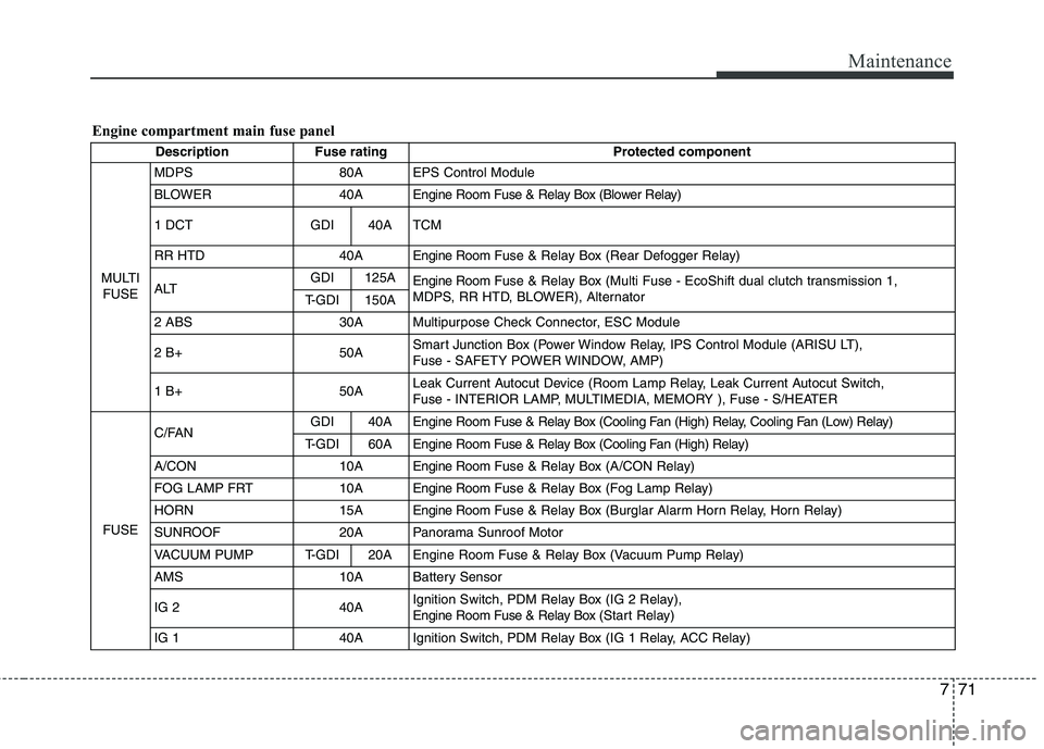
Engine compartment main fuse panel
Description Fuse rating Protected component
MULTI
FUSEMDPS 80A EPS Control Module
BLOWER 40A Engine Room Fuse & Relay Box (Blower Relay)
1 DCT GDI 40A TCM
RR HTD 40A Engine RoomFuse & Relay Box (Rear Defogger Relay)
ALTGDI 125A
Engine RoomFuse & Relay Box (Multi Fuse - EcoShift dual clutch transmission 1,
MDPS, RR HTD, BLOWER), Alternator
T-GDI 150A
2 ABS 30A Multipurpose Check Connector, ESC Module
2 B+ 50ASmart Junction Box (Power Window Relay, IPS Control Module (ARISU LT),
Fuse - SAFETY POWER WINDOW, AMP)
1 B+50ALeak Current Autocut Device (Room Lamp Relay, Leak Current Autocut Switch,
Fuse - INTERIOR LAMP, MULTIMEDIA, MEMORY ), Fuse - S/HEATER
FUSEC/FANGDI 40A Engine Room Fuse & Relay Box (Cooling Fan (High) Relay, Cooling Fan (Low) Relay)
T-GDI 60AEngine Room Fuse & Relay Box (Cooling Fan (High) Relay)
A/CON 10AEngine RoomFuse & Relay Box (A/CON Relay)
FOG LAMP FRT 10AEngine RoomFuse & Relay Box (Fog Lamp Relay)
HORN 15AEngine RoomFuse & Relay Box (Burglar Alarm Horn Relay, Horn Relay)
SUNROOF 20A Panorama Sunroof Motor
VACUUM PUMP T-GDI 20A Engine Room Fuse & Relay Box (Vacuum Pump Relay)
AMS 10A Battery Sensor
IG 2 40AIgnition Switch, PDM Relay Box (IG 2 Relay),
Engine Room Fuse & Relay Box (Start Relay)
IG 1 40A Ignition Switch, PDM Relay Box (IG 1 Relay, ACC Relay)
Page 348 of 384
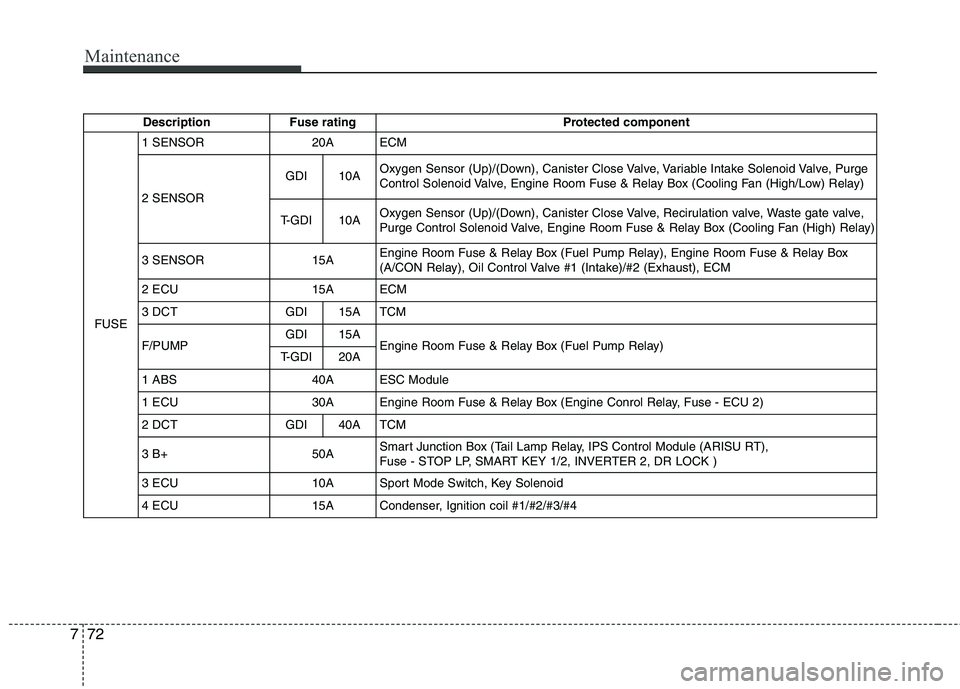
Maintenance
72 7
Description Fuse rating Protected component
FUSE1 SENSOR 20A ECM
2 SENSORGDI 10AOxygen Sensor (Up)/(Down), Canister Close Valve, Variable Intake Solenoid Valve, Purge
Control Solenoid Valve, Engine Room Fuse & Relay Box (Cooling Fan (High/Low) Relay)
T-GDI 10AOxygen Sensor (Up)/(Down), Canister Close Valve, Recirulation valve, Waste gate valve,
Purge Control Solenoid Valve, Engine Room Fuse & Relay Box (Cooling Fan (High) Relay)
3 SENSOR 15AEngine Room Fuse & Relay Box (Fuel Pump Relay), Engine Room Fuse & Relay Box
(A/CON Relay), Oil Control Valve #1 (Intake)/#2 (Exhaust), ECM
2 ECU 15A ECM
3 DCT GDI 15A TCM
F/PUMPGDI 15A
Engine Room Fuse & Relay Box (Fuel Pump Relay)
T-GDI 20A
1 ABS 40A ESC Module
1 ECU 30A Engine Room Fuse & Relay Box (Engine Conrol Relay, Fuse - ECU 2)
2 DCT GDI 40A TCM
3 B+ 50ASmart Junction Box (Tail Lamp Relay, IPS Control Module (ARISU RT),
Fuse - STOP LP, SMART KEY 1/2, INVERTER 2, DR LOCK )
3 ECU 10A Sport Mode Switch, Key Solenoid
4 ECU 15A Condenser, Ignition coil #1/#2/#3/#4