fuse box HYUNDAI VELOSTER 2015 Owners Manual
[x] Cancel search | Manufacturer: HYUNDAI, Model Year: 2015, Model line: VELOSTER, Model: HYUNDAI VELOSTER 2015Pages: 384, PDF Size: 25 MB
Page 16 of 384
Your vehicle at a glance
2 2
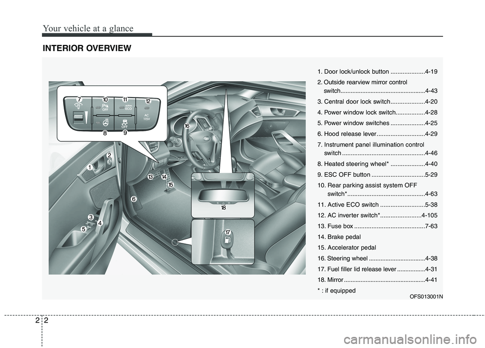
INTERIOR OVERVIEW
OFS013001N
1. Door lock/unlock button ....................4-19
2. Outside rearview mirror control
switch...................................................4-43
3. Central door lock switch....................4-20
4. Power window lock switch.................4-28
5. Power window switches ....................4-25
6. Hood release lever ............................4-29
7. Instrument panel illumination control
switch ................................................4-46
8. Heated steering wheel* ....................4-40
9. ESC OFF button ...............................5-29
10. Rear parking assist system OFF
switch*.............................................4-63
11. Active ECO switch ..........................5-38
12. AC inverter switch*........................4-105
13. Fuse box .........................................7-63
14. Brake pedal
15. Accelerator pedal
16. Steering wheel ..................................4-38
17. Fuel filler lid release lever .................4-31
18. Mirror .................................................4-41
* : if equipped
Page 18 of 384
Your vehicle at a glance
4 2
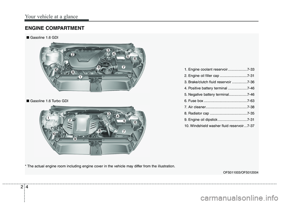
ENGINE COMPARTMENT
1. Engine coolant reservoir ...................7-33
2. Engine oil filler cap ...........................7-31
3. Brake/clutch fluid reservoir ...............7-36
4. Positive battery terminal ...................7-46
5. Negative battery terminal..................7-46
6. Fuse box ...........................................7-63
7. Air cleaner.........................................7-38
8. Radiator cap .....................................7-35
9. Engine oil dipstick .............................7-31
10. Windshield washer fluid reservoir ...7-37
OFS011003/OFS012004
* The actual engine room including engine cover in the vehicle may differ from the illustration.■Gasoline 1.6 GDI
■Gasoline 1.6 Turbo GDI
Page 56 of 384
Safety features of your vehicle
38 3
WARNING
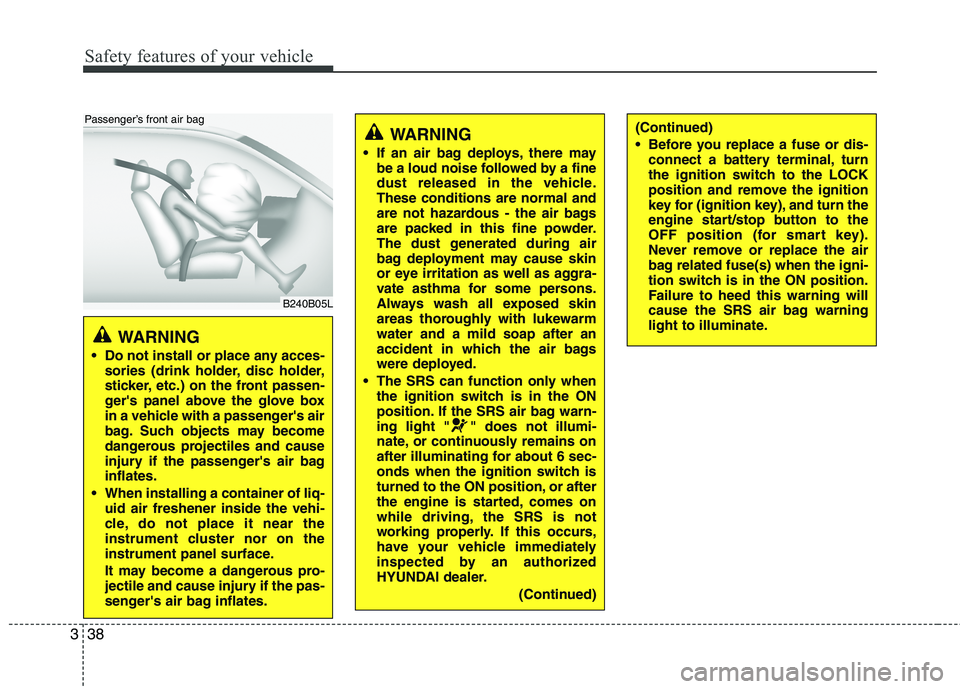
Do not install or place any acces-
sories (drink holder, disc holder,
sticker, etc.) on the front passen-
ger's panel above the glove box
in a vehicle with a passenger's air
bag. Such objects may become
dangerous projectiles and cause
injury if the passenger's air bag
inflates.
When installing a container of liq-
uid air freshener inside the vehi-
cle, do not place it near the
instrument cluster nor on the
instrument panel surface.
It may become a dangerous pro-
jectile and cause injury if the pas-
senger's air bag inflates.
B240B05L
Passenger’s front air bag
WARNING
If an air bag deploys, there may
be a loud noise followed by a fine
dust released in the vehicle.
These conditions are normal and
are not hazardous - the air bags
are packed in this fine powder.
The dust generated during air
bag deployment may cause skin
or eye irritation as well as aggra-
vate asthma for some persons.
Always wash all exposed skin
areas thoroughly with lukewarm
water and a mild soap after an
accident in which the air bags
were deployed.
The SRS can function only when
the ignition switch is in the ON
position. If the SRS air bag warn-
ing light " " does not illumi-
nate, or continuously remains on
after illuminating for about 6 sec-
onds when the ignition switch is
turned to the ON position, or after
the engine is started, comes on
while driving, the SRS is not
working properly. If this occurs,
have your vehicle immediately
inspected by an authorized
HYUNDAI dealer.
(Continued)
(Continued)
Before you replace a fuse or dis-
connect a battery terminal, turn
the ignition switch to the LOCK
position and remove the ignition
key for (ignition key), and turn the
engine start/stop button to the
OFF position (for smart key).
Never remove or replace the air
bag related fuse(s) when the igni-
tion switch is in the ON position.
Failure to heed this warning will
cause the SRS air bag warning
light to illuminate.
Page 278 of 384
Maintenance
2 7
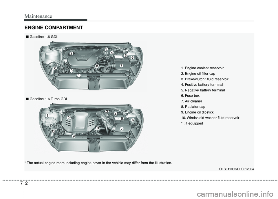
ENGINE COMPARTMENT
1. Engine coolant reservoir
2. Engine oil filler cap
3. Brake/clutch* fluid reservoir
4. Positive battery terminal
5. Negative battery terminal
6. Fuse box
7. Air cleaner
8. Radiator cap
9. Engine oil dipstick
10. Windshield washer fluid reservoir
* : if equipped
OFS011003/OFS012004
* The actual engine room including engine cover in the vehicle may differ from the illustration.■Gasoline 1.6 GDI
■Gasoline 1.6 Turbo GDI
Page 344 of 384
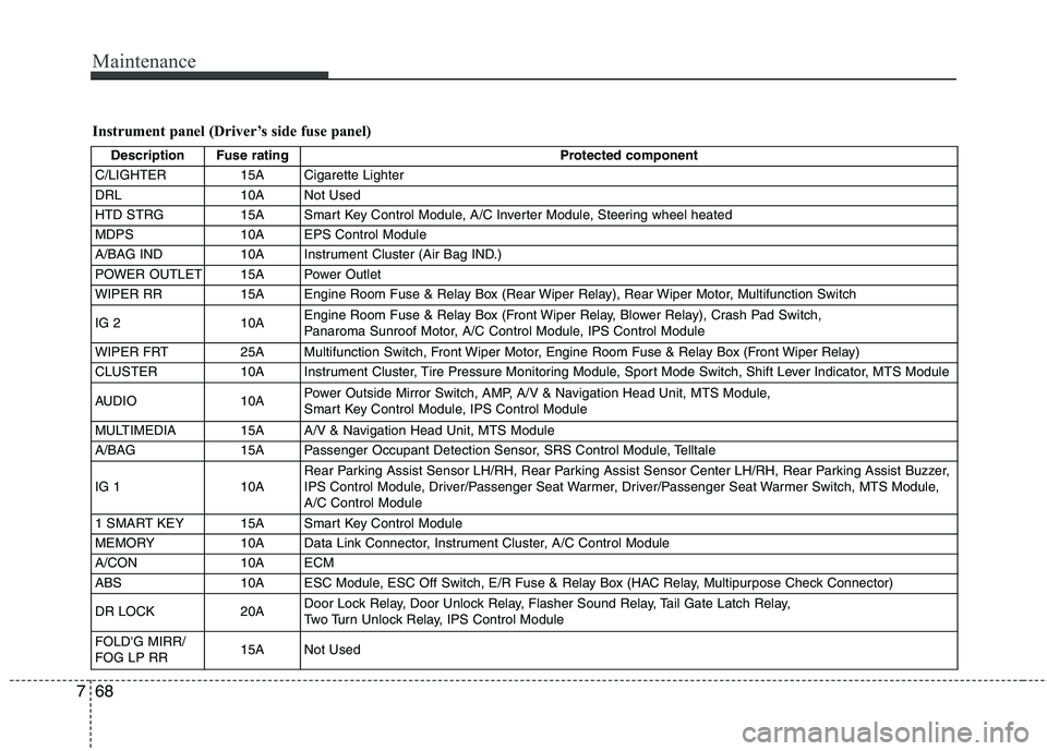
Maintenance
68 7
Instrument panel (Driver’s side fuse panel)
Description Fuse rating Protected component
C/LIGHTER 15A Cigarette Lighter
DRL 10A Not Used
HTD STRG 15A Smart Key Control Module, A/C Inverter Module, Steering wheel heated
MDPS 10A EPS Control Module
A/BAG IND 10A Instrument Cluster (Air Bag IND.)
POWER OUTLET 15A Power Outlet
WIPER RR 15A Engine Room Fuse & Relay Box (Rear Wiper Relay), Rear Wiper Motor, Multifunction Switch
IG 2 10AEngine Room Fuse & Relay Box (Front Wiper Relay, Blower Relay), Crash Pad Switch,
Panaroma Sunroof Motor, A/C Control Module, IPS Control Module
WIPER FRT 25A Multifunction Switch, Front Wiper Motor, Engine Room Fuse & Relay Box (Front Wiper Relay)
CLUSTER 10A Instrument Cluster, Tire Pressure Monitoring Module, Sport Mode Switch, Shift Lever Indicator, MTS Module
AUDIO 10APower Outside Mirror Switch, AMP, A/V & Navigation Head Unit, MTS Module,
Smart Key Control Module, IPS Control Module
MULTIMEDIA 15A A/V & Navigation Head Unit, MTS Module
A/BAG 15A Passenger Occupant Detection Sensor, SRS Control Module, Telltale
IG 1 10ARear Parking Assist Sensor LH/RH, Rear Parking Assist Sensor Center LH/RH, Rear Parking Assist Buzzer,
IPS Control Module, Driver/Passenger Seat Warmer, Driver/Passenger Seat Warmer Switch, MTS Module,
A/C Control Module
1 SMART KEY 15A Smart Key Control Module
MEMORY 10A Data Link Connector, Instrument Cluster, A/C Control Module
A/CON 10A ECM
ABS 10A ESC Module, ESC Off Switch, E/R Fuse & Relay Box (HAC Relay, Multipurpose Check Connector)
DR LOCK 20ADoor Lock Relay, Door Unlock Relay, Flasher Sound Relay, Tail Gate Latch Relay,
Two Turn Unlock Relay, IPS Control Module
FOLD'G MIRR/
FOG LP RR15A Not Used
Page 345 of 384
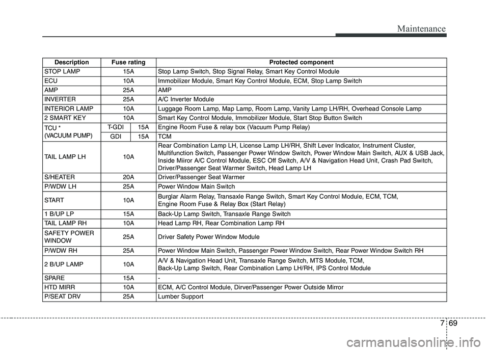
769
Maintenance
Description Fuse rating Protected component
STOP LAMP 15A Stop Lamp Switch, Stop Signal Relay, Smart Key Control Module
ECU 10A Immobilizer Module, Smart Key Control Module, ECM, Stop Lamp Switch
AMP 25A AMP
INVERTER 25A A/C Inverter Module
INTERIOR LAMP 10A Luggage Room Lamp, Map Lamp, Room Lamp, Vanity Lamp LH/RH, Overhead Console Lamp
2 SMART KEY 10A Smart Key Control Module, Immobilizer Module, Start Stop Button Switch
TCU *
(VACUUM PUMP)T-GDI 15A Engine Room Fuse & relay box (Vacuum Pump Relay)
GDI 15A TCM
TAIL LAMP LH 10ARear Combination Lamp LH, License Lamp LH/RH, Shift Lever Indicator, Instrument Cluster,
Multifunction Switch, Passenger Power Window Switch, Power Window Main Switch, AUX & USB Jack,
Inside Miiror A/C Control Module, ESC Off Switch, A/V & Navigation Head Unit, Crash Pad Switch,
Driver/Passenger Seat Warmer Switch, Head Lamp LH
S/HEATER 20A Driver/Passenger Seat Warmer
P/WDW LH 25A Power Window Main Switch
START 10ABurglar Alarm Relay, Transaxle Range Switch, Smart Key Control Module, ECM, TCM,
Engine Room Fuse & Relay Box (Start Relay)
1 B/UP LP 15A Back-Up Lamp Switch, Transaxle Range Switch
TAIL LAMP RH 10A Head Lamp RH, Rear Combination Lamp RH
SAFETY POWER
WINDOW25A Driver Safety Power Window Module
P/WDW RH 25A Power Window Main Switch, Passenger Power Window Switch, Rear Power Window Switch RH
2 B/UP LAMP 10AA/V & Navigation Head Unit, Transaxle Range Switch, MTS Module, TCM,
Back-Up Lamp Switch, Rear Combination Lamp LH/RH, IPS Control Module
SPARE 15A -
HTD MIRR 10A ECM, A/C Control Module, Dirver/Passenger Power Outside Mirror
P/SEAT DRV 25A Lumber Support
Page 347 of 384
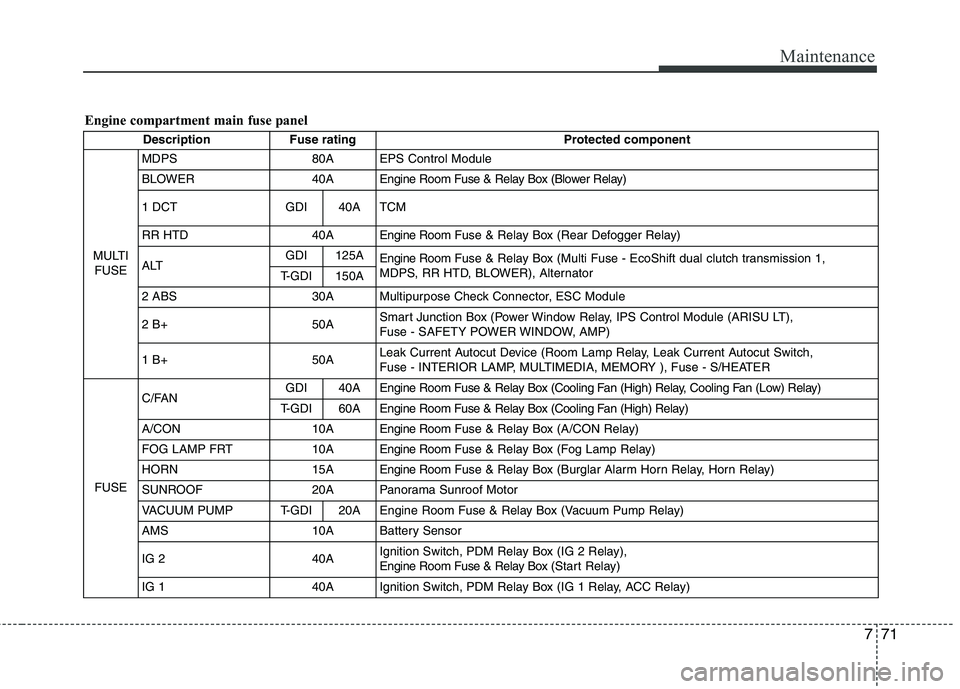
771
Maintenance
Engine compartment main fuse panel
Description Fuse rating Protected component
MULTI
FUSEMDPS 80A EPS Control Module
BLOWER 40A Engine Room Fuse & Relay Box (Blower Relay)
1 DCT GDI 40A TCM
RR HTD 40A Engine RoomFuse & Relay Box (Rear Defogger Relay)
ALTGDI 125A
Engine RoomFuse & Relay Box (Multi Fuse - EcoShift dual clutch transmission 1,
MDPS, RR HTD, BLOWER), Alternator
T-GDI 150A
2 ABS 30A Multipurpose Check Connector, ESC Module
2 B+ 50ASmart Junction Box (Power Window Relay, IPS Control Module (ARISU LT),
Fuse - SAFETY POWER WINDOW, AMP)
1 B+50ALeak Current Autocut Device (Room Lamp Relay, Leak Current Autocut Switch,
Fuse - INTERIOR LAMP, MULTIMEDIA, MEMORY ), Fuse - S/HEATER
FUSEC/FANGDI 40A Engine Room Fuse & Relay Box (Cooling Fan (High) Relay, Cooling Fan (Low) Relay)
T-GDI 60AEngine Room Fuse & Relay Box (Cooling Fan (High) Relay)
A/CON 10AEngine RoomFuse & Relay Box (A/CON Relay)
FOG LAMP FRT 10AEngine RoomFuse & Relay Box (Fog Lamp Relay)
HORN 15AEngine RoomFuse & Relay Box (Burglar Alarm Horn Relay, Horn Relay)
SUNROOF 20A Panorama Sunroof Motor
VACUUM PUMP T-GDI 20A Engine Room Fuse & Relay Box (Vacuum Pump Relay)
AMS 10A Battery Sensor
IG 2 40AIgnition Switch, PDM Relay Box (IG 2 Relay),
Engine Room Fuse & Relay Box (Start Relay)
IG 1 40A Ignition Switch, PDM Relay Box (IG 1 Relay, ACC Relay)
Page 348 of 384
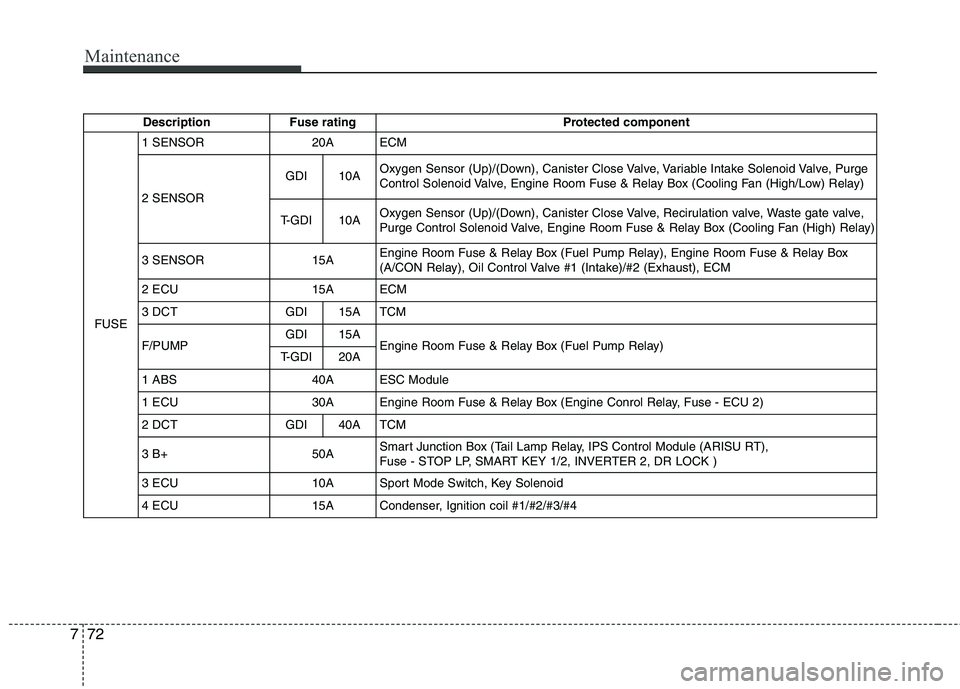
Maintenance
72 7
Description Fuse rating Protected component
FUSE1 SENSOR 20A ECM
2 SENSORGDI 10AOxygen Sensor (Up)/(Down), Canister Close Valve, Variable Intake Solenoid Valve, Purge
Control Solenoid Valve, Engine Room Fuse & Relay Box (Cooling Fan (High/Low) Relay)
T-GDI 10AOxygen Sensor (Up)/(Down), Canister Close Valve, Recirulation valve, Waste gate valve,
Purge Control Solenoid Valve, Engine Room Fuse & Relay Box (Cooling Fan (High) Relay)
3 SENSOR 15AEngine Room Fuse & Relay Box (Fuel Pump Relay), Engine Room Fuse & Relay Box
(A/CON Relay), Oil Control Valve #1 (Intake)/#2 (Exhaust), ECM
2 ECU 15A ECM
3 DCT GDI 15A TCM
F/PUMPGDI 15A
Engine Room Fuse & Relay Box (Fuel Pump Relay)
T-GDI 20A
1 ABS 40A ESC Module
1 ECU 30A Engine Room Fuse & Relay Box (Engine Conrol Relay, Fuse - ECU 2)
2 DCT GDI 40A TCM
3 B+ 50ASmart Junction Box (Tail Lamp Relay, IPS Control Module (ARISU RT),
Fuse - STOP LP, SMART KEY 1/2, INVERTER 2, DR LOCK )
3 ECU 10A Sport Mode Switch, Key Solenoid
4 ECU 15A Condenser, Ignition coil #1/#2/#3/#4
Page 380 of 384
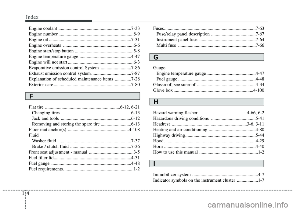
Index
4I
Engine coolant ..............................................................7-33
Engine number ................................................................8-9
Engine oil ......................................................................7-31
Engine overheats ............................................................6-6
Engine start/stop button ..................................................5-8
Engine temperature gauge ............................................4-47
Engine will not start ........................................................6-3
Evaporative emission control System ..........................7-86
Exhaust emission control system ..................................7-87
Explanation of scheduled maintenance items ..............7-28
Exterior care ..................................................................7-80
Flat tire ................................................................6-12, 6-21
Changing tires ............................................................6-13
Jack and tools ............................................................6-12
Removing and storing the spare tire ..........................6-13
Floor mat anchor(s) ....................................................4-108
Fluid
Washer fluid ..............................................................7-37
Brake / clutch fluid ....................................................7-36
Front seat adjustment - manual ......................................3-5
Fuel filler lid..................................................................4-31
Fuel gauge ....................................................................4-48
Fuel requirements ............................................................1-2Fuses ..............................................................................7-63
Fuse/relay panel description ......................................7-67
Instrument panel fuse ................................................7-64
Multi fuse ..................................................................7-66
Gauge
Engine temperature gauge ..........................................4-47
Fuel gauge ..................................................................4-48
Glassroof, see sunroof ..................................................4-34
Glove box ....................................................................4-100
Hazard warning flasher ..........................................4-66, 6-2
Hazardous driving conditions ......................................5-41
Headrest ................................................................3-6, 3-11
Heating and air conditioning ........................................4-80
Highway driving............................................................5-44
Hood ..............................................................................4-29
Horn ..............................................................................4-40
How to use this manual ..................................................1-2
Immobilizer system ........................................................4-7
Indicator symbols on the instrument cluster ..................1-7
F
G
H
I