tire pressure HYUNDAI VELOSTER 2019 Owner's Manual
[x] Cancel search | Manufacturer: HYUNDAI, Model Year: 2019, Model line: VELOSTER, Model: HYUNDAI VELOSTER 2019Pages: 491, PDF Size: 15.17 MB
Page 357 of 491
6-13
What to do in an emergency
6
You may not be able identify a tire
with low pressure by simply looking
at it. Always use a good quality tire
pressure gage to measure the tire's
inflation pressure. Please note that a
tire that is hot (from being driven) will
have a higher pressure measure-
ment than a tire that is cold.
A cold tire means the vehicle has
been sitting for 3 hours and driven for
less than 1 mile (1.6 km) in that 3
hour period.
Allow the tire to cool before measur-
ing the inflation pressure. Always be
sure the tire is cold before inflating to
the recommended pressure.Information
This device complies with Part 15 of
the FCC rules.
Operation is subject to the following
three conditions:
1. This device may not cause harmfulinterference.
2. This device must accept any inter- ference received, including interfer-
ence that may cause undesired
operation.
3. Changes or modifications not expressly approved by the party
responsible for compliance could
void the user's authority to operate
the equipment.
i
The TPMS cannot alert you to
severe and sudden tire dam-
age caused by external fac-
tors such as nails or road
debris.
If you feel any vehicle instabil-
ity, immediately take your foot
off the accelerator, apply the
brakes gradually with light
force, and slowly move to a
safe position off the road.
WARNING
Tampering with, modifying, or
disabling the Tire Pressure
Monitoring System (TPMS)
components may interfere with
the system's ability to warn the
driver of low tire pressure con-
ditions and/or TPMS malfunc-
tions. Tampering with, modify-
ing, or disabling the Tire
Pressure Monitoring System
(TPMS) components may void
the warranty for that portion of
the vehicle.
WARNING
Page 361 of 491
6-17
What to do in an emergency
6
9. Loosen the lug nuts with the wheellug nut wrench and remove them
with your fingers. Remove the
wheel from the studs and lay it flat
on the ground out of the way.
Remove any dirt or debris from
the studs, mounting surfaces, and
wheel.
10. Install the spare tire onto the studs of the hub.
11. Tighten the lug nuts with your fin- gers onto the studs with the
smaller end of the lug nuts clos-
est to the wheel.
12. Lower the vehicle to the ground by turning the jack handle coun-
terclockwise.
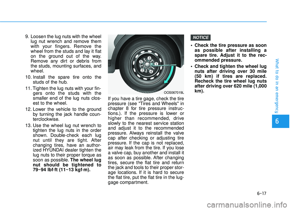
13. Use the wheel lug nut wrench to tighten the lug nuts in the order
shown. Double-check each lug
nut until they are tight. After
changing tires, have an author-
ized HYUNDAI dealer tighten the
lug nuts to their proper torque as
soon as possible. The wheel lug
nut should be tightened to
79~94 lbf·ft (11~13 kgf·m). If you have a tire gage, check the tire
pressure (see "Tires and Wheels" in
chapter 8 for tire pressure instruc-
tions.). If the pressure is lower or
higher than recommended, drive
slowly to the nearest service station
and adjust it to the recommended
pressure. Always reinstall the valve
cap after checking or adjusting tire
pressure. If the cap is not replaced,
air may leak from the tire. If you lose
a valve cap, buy another and install it
as soon as possible. After changing
tires, secure the flat tire and return
the jack and tools to their proper stor-
age locations. If it is hard to secure
the flat tire, put the flat tire in the lug-
gage compartment. Check the tire pressure as soon
as possible after installing a
spare tire. Adjust it to the rec-
ommended pressure.
Check and tighten the wheel lug nuts after driving over 30 mile
(50 km) if tires are replaced.
Recheck the tire wheel lug nuts
after driving over 620 mile (1,000
km).NOTICE
OOS067019L
Page 362 of 491
6-18
What to do in an emergency
If any of the equipment such as the
jack, lug nuts, studs, or other equip-
ment is damaged or in poor condi-
tion, do not attempt to change the
tire and call for assistance.
Use of compact spare tires
Compact spare tires are designed for
emergency use only. Drive carefully
on the compact spare tire and
always follow the safety precautions. When driving with the compact spare
tire mounted to your vehicle:
Check the tire pressure after
installing the compact spare tire.
The compact spare tire should be
inflated to 60 psi (420 kPa).
Do not take this vehicle through an automatic car wash while the com-
pact spare tire is installed.
Do not use the compact spare tire on any other vehicle because this
tire has been designed especially
for your vehicle.
The compact spare tire’s tread life is shorter than a regular tire.
Inspect your compact spare tire
regularly and replace worn com-
pact spare tires with the same size
and design, mounted on the same
wheel.
Do not use more than one compact spare tire at a time.
When the original tire and wheel
are repaired and reinstalled on the
vehicle, the lug nut torque must be
set correctly. The correct lug nut
tightening torque is 79~94 lbf·ft
(11~13 kgf·m).
NOTICE
Your vehicle has metric threads
on the studs and lug nuts. Make
certain during tire changing that
the same nuts that were
removed are reinstalled. If you
have to replace your lug nuts
make sure they have metric
threads to avoid damaging the
studs and ensure the wheel is
properly secured to the hub.
Consult an authorized HYUNDAI
dealer for assistance.
CAUTION
To prevent compact spare tire
failure and loss of control pos-
sibly resulting in an accident:
Use the compact spare tire
only in an emergency.
NEVER operate your vehicle
over 50 mph (80 km/h).
Do not exceed the vehicle's
maximum load rating or the
load carrying capacity shown
on the sidewall of the com-
pact spare tire.
Do not use the compact spare
tire continuously. Repair or
replace the original tire as
soon as possible to avoid fail-
ure of the compact spare tire.
WARNING
Page 364 of 491
6-20
With Tire Mobility Kit (TMK)
(if equipped)
For safe operation, carefully read
and follow the instructions in this
manual before use.
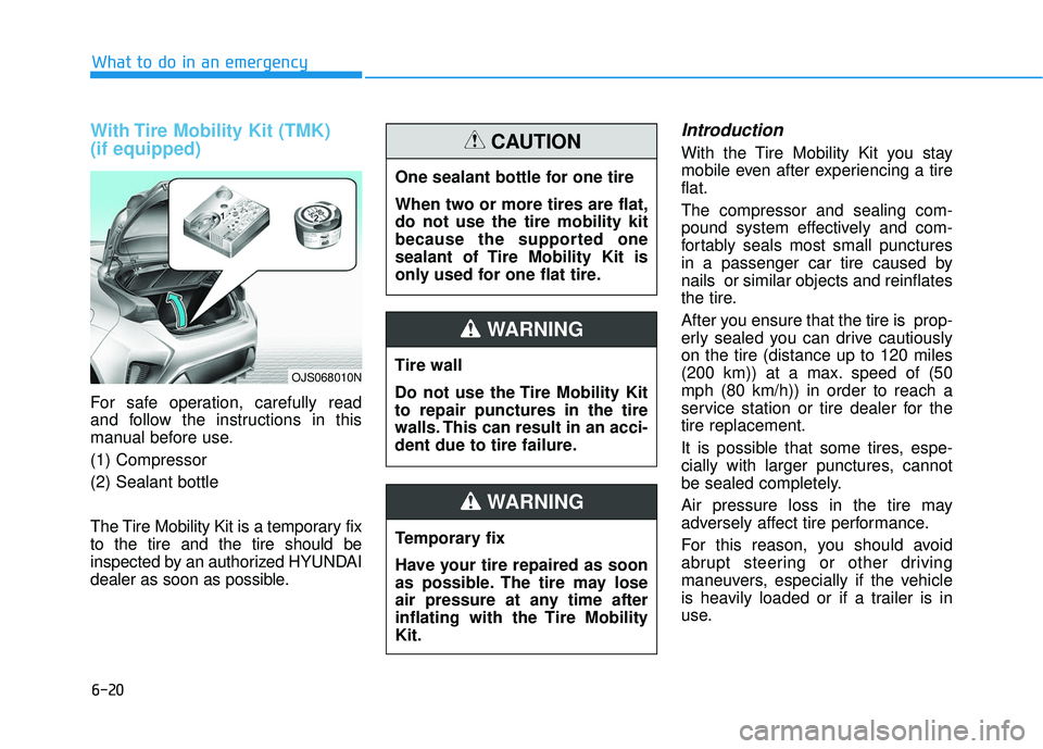
(1) Compressor
(2) Sealant bottle
The Tire Mobility Kit is a temporary fix
to the tire and the tire should be
inspected by an authorized HYUNDAI
dealer as soon as possible.
Introduction
With the Tire Mobility Kit you stay
mobile even after experiencing a tire
flat.
The compressor and sealing com-
pound system effectively and com-
fortably seals most small punctures
in a passenger car tire caused by
nails or similar objects and reinflates
the tire.
After you ensure that the tire is prop-
erly sealed you can drive cautiously
on the tire (distance up to 120 miles
(200 km)) at a max. speed of (50
mph (80 km/h)) in order to reach a
service station or tire dealer for the
tire replacement.
It is possible that some tires, espe-
cially with larger punctures, cannot
be sealed completely.
Air pressure loss in the tire may
adversely affect tire performance.
For this reason, you should avoid
abrupt steering or other driving
maneuvers, especially if the vehicle
is heavily loaded or if a trailer is in
use.
What to do in an emergency
OJS068010N
One sealant bottle for one tire
When two or more tires are flat,
do not use the tire mobility kit
because the supported one
sealant of Tire Mobility Kit is
only used for one flat tire.
CAUTION
Tire wall
Do not use the Tire Mobility Kit
to repair punctures in the tire
walls. This can result in an acci-
dent due to tire failure.
WARNING
Temporary fix
Have your tire repaired as soon
as possible. The tire may lose
air pressure at any time after
inflating with the Tire Mobility
Kit.
WARNING
Page 366 of 491
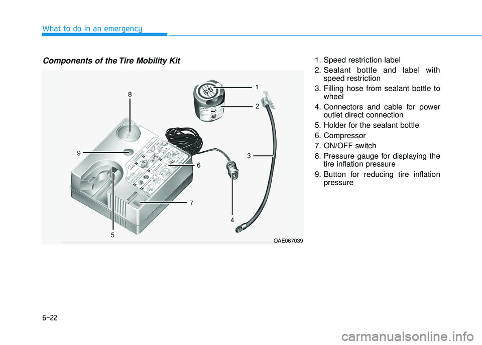
6-22
1. Speed restriction label
2. Sealant bottle and label withspeed restriction
3. Filling hose from sealant bottle to wheel
4. Connectors and cable for power outlet direct connection
5. Holder for the sealant bottle
6. Compressor
7. ON/OFF switch
8. Pressure gauge for displaying the tire inflation pressure
9. Button for reducing tire inflation pressure
What to do in an emergency
Components of the Tire Mobility Kit
OAE067039
Page 367 of 491
6-23
What to do in an emergency
Connectors, cable and connection
hose are stored in the compressor
housing.
Strictly follow the specified sequence,
otherwise the sealant may escape
under high pressure.Using the Tire Mobility Kit
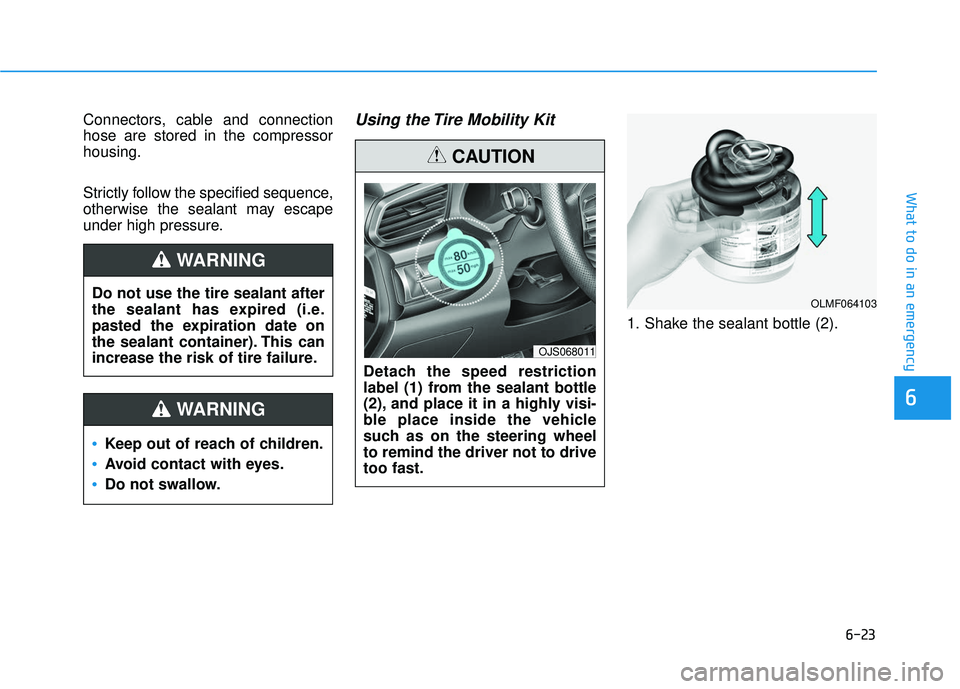
1. Shake the sealant bottle (2).
6
Do not use the tire sealant after
the sealant has expired (i.e.
pasted the expiration date on
the sealant container). This can
increase the risk of tire failure.
WARNING
Keep out of reach of children.
Avoid contact with eyes.
Do not swallow.
WARNING
Detach the speed restriction
label (1) from the sealant bottle
(2), and place it in a highly visi-
ble place inside the vehicle
such as on the steering wheel
to remind the driver not to drive
too fast.
CAUTION
OJS068011
OLMF064103
Page 368 of 491
6-24
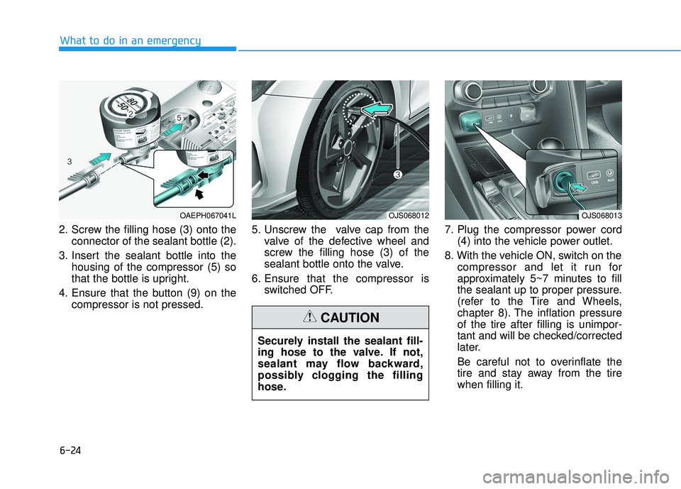
2. Screw the filling hose (3) onto theconnector of the sealant bottle (2).
3. Insert the sealant bottle into the housing of the compressor (5) so
that the bottle is upright.
4. Ensure that the button (9) on the compressor is not pressed. 5. Unscrew the valve cap from the
valve of the defective wheel and
screw the filling hose (3) of the
sealant bottle onto the valve.
6. Ensure that the compressor is switched OFF. 7. Plug the compressor power cord
(4) into the vehicle power outlet.
8. With the vehicle ON, switch on the compressor and let it run for
approximately 5~7 minutes to fill
the sealant up to proper pressure.
(refer to the Tire and Wheels,
chapter 8). The inflation pressure
of the tire after filling is unimpor-
tant and will be checked/corrected
later.
Be careful not to overinflate the
tire and stay away from the tire
when filling it.
What to do in an emergency
OJS068012OJS068013
Securely install the sealant fill-
ing hose to the valve. If not,
sealant may flow backward,
possibly clogging the filling
hose.
CAUTION
OAEPH067041L
Page 369 of 491
6-25
What to do in an emergency
9. Switch off the compressor.
10. Detach the hoses from thesealant bottle connector and
from the tire valve.
Return the Tire Mobility Kit to its stor-
age location in the vehicle.
Distributing the sealant
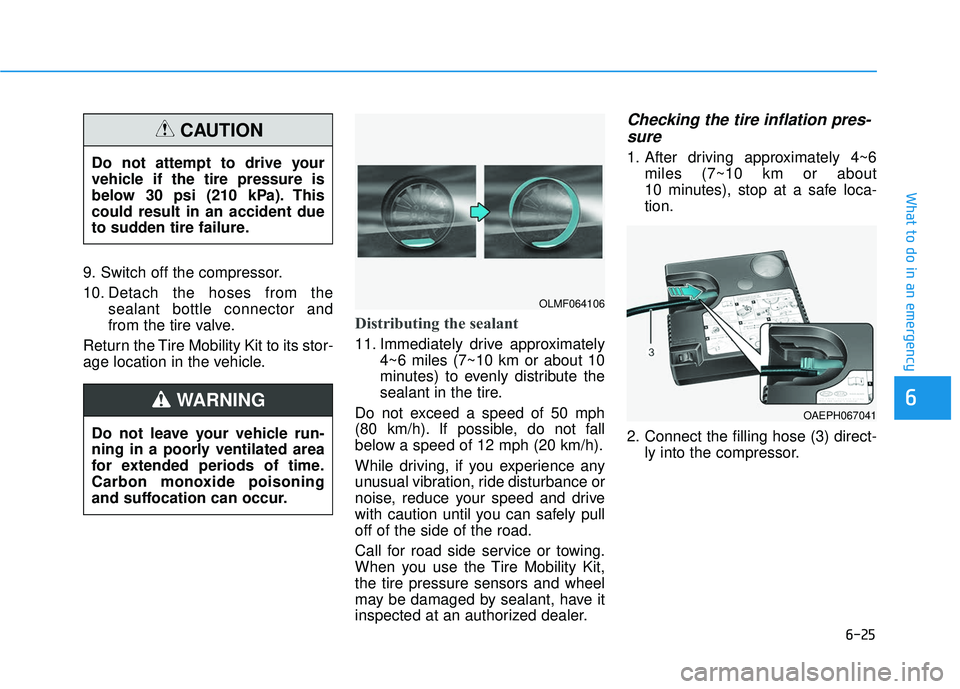
11. Immediately drive approximately 4~6 miles (7~10 km or about 10
minutes) to evenly distribute the
sealant in the tire.
Do not exceed a speed of 50 mph
(80 km/h). If possible, do not fall
below a speed of 12 mph (20 km/h).
While driving, if you experience any
unusual vibration, ride disturbance or
noise, reduce your speed and drive
with caution until you can safely pull
off of the side of the road.
Call for road side service or towing.
When you use the Tire Mobility Kit,
the tire pressure sensors and wheel
may be damaged by sealant, have it
inspected at an authorized dealer.
Checking the tire inflation pres- sure
1. After driving approximately 4~6
miles (7~10 km or about
10 minutes), stop at a safe loca-
tion.
2. Connect the filling hose (3) direct- ly into the compressor.
6
Do not attempt to drive your
vehicle if the tire pressure is
below 30 psi (210 kPa). This
could result in an accident due
to sudden tire failure.
CAUTION
Do not leave your vehicle run-
ning in a poorly ventilated area
for extended periods of time.
Carbon monoxide poisoning
and suffocation can occur.
WARNING
OLMF064106
OAEPH067041
Page 370 of 491
6-26
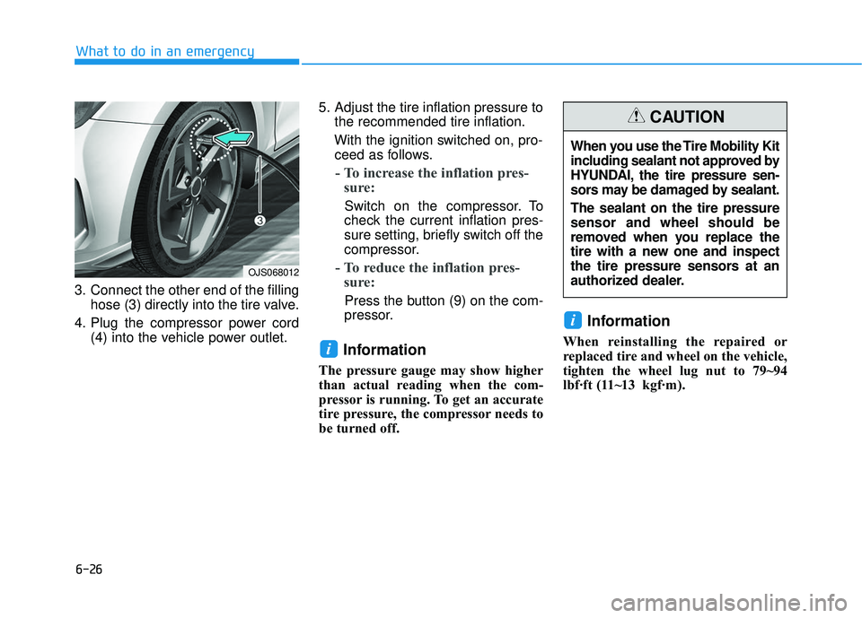
3. Connect the other end of the fillinghose (3) directly into the tire valve.
4. Plug the compressor power cord (4) into the vehicle power outlet. 5. Adjust the tire inflation pressure to
the recommended tire inflation.
With the ignition switched on, pro- ceed as follows.
- To increase the inflation pres- sure:
Switch on the compressor. To
check the current inflation pres-
sure setting, briefly switch off the
compressor.
- To reduce the inflation pres- sure:
Press the button (9) on the com-
pressor.
Information
The pressure gauge may show higher
than actual reading when the com-
pressor is running. To get an accurate
tire pressure, the compressor needs to
be turned off.
Information
When reinstalling the repaired or
replaced tire and wheel on the vehicle,
tighten the wheel lug nut to 79~94
lbf·ft (1 1~13kgf·m).
i
i
What to do in an emergency
When you use the Tire Mobility Kit
including sealant not approved by
HYUNDAI, the tire pressure sen-
sors may be damaged by sealant.
The sealant on the tire pressure
sensor and wheel should be
removed when you replace the
tire with a new one and inspect
the tire pressure sensors at an
authorized dealer.
CAUTION
OJS068012
Page 376 of 491

7
Tires and wheels ..................................................7-37
Tire Care ........................................................................\
....7-37
Recommended Cold Tire Inflation Pressures ...........7-38
Check Tire Inflation Pressure ......................................7-39
Tire Rotation...................................................................\
..7-39
Wheel Alignment and Tire Balance ............................7-40
Tire Replacement ............................................................7-41
Wheel Replacement ........................................................7-42
Tire Traction .....................................................................7-4\
2
Tire Maintenance ............................................................7-42
Tire Sidewall Labeling ....................................................7-42
Tire Terminology and Definitions................................7-46
All Season Tires ...............................................................7-49
Summer Tires ...................................................................7-49
Snow Tires ........................................................................\
7-50
Radial-Ply Tires ...............................................................7-50
Low Aspect Ratio Tires..................................................7-50
Fuses ......................................................................7-\
52
Instrument Panel Fuse Replacement..........................7-53
Engine Compartment Panel Fuse Replacement.......7-54
Fuse/Relay Panel Description ......................................7-56
Light bulbs.............................................................7-67
Headlamp, Position lamp, Daytime Running Light,
Turn signal lamp and Side marker ..............................7-68
Side Repeater Lamp Replacement ..............................7-72
Rear Combination Light Bulb Replacement ..............7-73
High Mounted Stop Lamp Replacement ....................7-76
License Plate Light Bulb Replacement ......................7-76
Interior Light Bulb Replacement .................................7-77
Appearance care ..................................................7-78
Exterior Care ....................................................................7-78\
Interior Care .....................................................................7-8\
3
Emission control system .....................................7-86
Crankcase Emission Control System ..........................7-86
Evaporative Emission Control System Including
Onboard Refueling Vapor Recovery (ORVR)............7-86
Exhaust Emission Control System ..............................7-87
California perchlorate notice .............................7-90