instrument panel HYUNDAI VERACRUZ 2008 User Guide
[x] Cancel search | Manufacturer: HYUNDAI, Model Year: 2008, Model line: VERACRUZ, Model: HYUNDAI VERACRUZ 2008Pages: 440, PDF Size: 7.67 MB
Page 71 of 440
351
Safety features of your vehicle
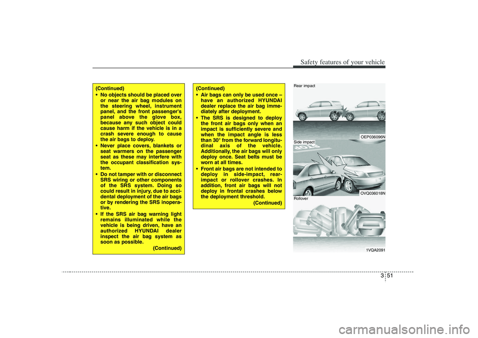
OEP036096NOVQ036018N1VQA2091
Rear impactSide impactRollover
(Continued)
No objects should be placed over
or near the air bag modules on
the steering wheel, instrument
panel, and the front passenger's
panel above the glove box,
because any such object could
cause harm if the vehicle is in a
crash severe enough to cause
the air bags to deploy.
Never place covers, blankets or
seat warmers on the passenger
seat as these may interfere with
the occupant classification sys-
tem.
Do not tamper with or disconnect
SRS wiring or other components
of the SRS system. Doing so
could result in injury, due to acci-
dental deployment of the air bags
or by rendering the SRS inopera-
tive.
If the SRS air bag warning light
remains illuminated while the
vehicle is being driven, have an
authorized HYUNDAI dealer
inspect the air bag system as
soon as possible.
(Continued)
(Continued)
Air bags can only be used once –
have an authorized HYUNDAI
dealer replace the air bag imme-
diately after deployment.
The SRS is designed to deploy
the front air bags only when an
impact is sufficiently severe and
when the impact angle is less
than 30° from the forward longitu-
dinal axis of the vehicle.
Additionally, the air bags will only
deploy once. Seat belts must be
worn at all times.
Front air bags are not intended to
deploy in side-impact, rear-
impact or rollover crashes. In
addition, front air bags will not
deploy in frontal crashes below
the deployment threshold.
(Continued)
Page 80 of 440

Safety features of your vehicle60 3C041100AENSRS CareThe SRS is virtually maintenance-free
and so there are no parts you can safely
service by yourself. If the SRS "AIR BAG"
warning light does not illuminate, or con-
tinuously remains on, have your vehicle
immediately inspected by an authorized
HYUNDAI dealer.
Any work on the SRS system, such as
removing, installing, repairing, or any
work on the steering wheel must be per-
formed by an authorized HYUNDAI deal-
er. Improper handling of the SRS system
may result in serious personal injury.
WARNING
Modification to SRS components
or wiring, including the addition
of any kind of badges to the pad
covers or modifications to the
body structure, can adversely
affect SRS performance and lead
to possible injury.
For cleaning the air bag pad cov-
ers, use only a soft, dry cloth or
one which has been moistened
with plain water. Solvents or
cleaners could adversely affect
the air bag covers and proper
deployment of the system.
No objects should be placed over
or near the air bag modules on the
steering wheel, instrument panel,
and the front passenger's panel
above the glove box, because any
such object could cause harm if the
vehicle is in a crash severe enough
to cause the air bags to inflate.
(Continued)
(Continued)
If the air bags inflate, they must
be replaced by an authorized
HYUNDAI dealer.
Do not tamper with or disconnect
SRS wiring, or other components
of the SRS system. Doing so
could result in injury, due to acci-
dental inflation of the air bags or
by rendering the SRS inopera-
tive.
If components of the air bag sys-
tem must be discarded, or if the
vehicle must be scrapped, certain
safety precautions must be
observed. An authorized
HYUNDAI dealer knows these
precautions and can give you the
necessary information. Failure to
follow these precautions and pro-
cedures could increase the risk
of personal injury.
If your car was flooded and has
soaked carpeting or water on the
flooring, you shouldn't try to start
the engine; have the car towed to
an authorized HYUNDAI dealer.
Page 134 of 440
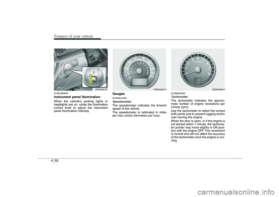
Features of your vehicle52 4D150100AUNInstrument panel illuminationWhen the vehicle’s parking lights or
headlights are on, rotate the illumination
control knob to adjust the instrument
panel illumination intensity.
GaugesD150201AUNSpeedometer The speedometer indicates the forward
speed of the vehicle.
The speedometer is calibrated in miles
per hour and/or kilometers per hour.
D150202AUNTachometer The tachometer indicates the approxi-
mate number of engine revolutions per
minute (rpm).
Use the tachometer to select the correct
shift points and to prevent lugging and/or
over-revving the engine.
When the door is open, or if the engine is
not started within 1 minute, the tachome-
ter pointer may move slightly in ON posi-
tion with the engine OFF. This movement
is normal and will not affect the accuracy
of the tachometer once the engine is run-
ning.
OEN046181
OEN046044
OEN046216
Page 153 of 440
471
Features of your vehicle
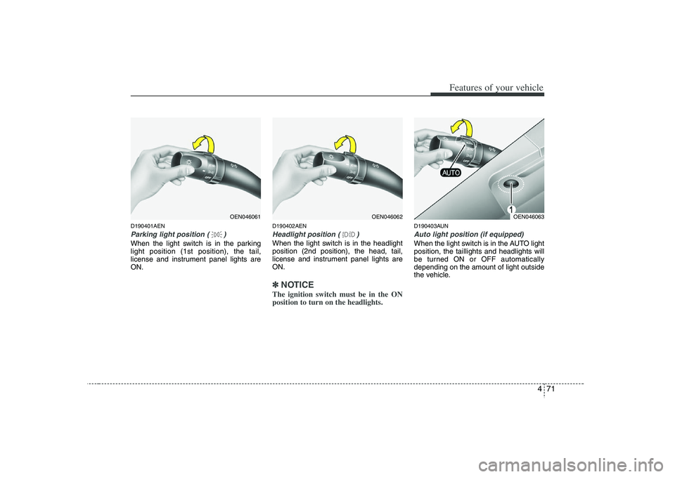
D190401AENParking light position ( )When the light switch is in the parking
light position (1st position), the tail,
license and instrument panel lights are
ON.
D190402AENHeadlight position ( )When the light switch is in the headlight
position (2nd position), the head, tail,
license and instrument panel lights are
ON.✽ ✽
NOTICEThe ignition switch must be in the ON
position to turn on the headlights.
D190403AUNAuto light position (if equipped)When the light switch is in the AUTO light
position, the taillights and headlights will
be turned ON or OFF automatically
depending on the amount of light outside
the vehicle.
OEN046062
OEN046061
OEN046063
Page 154 of 440
Features of your vehicle72 4
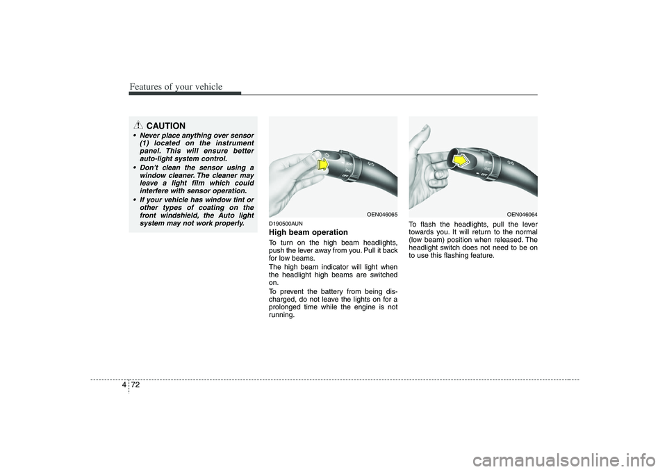
D190500AUNHigh beam operation To turn on the high beam headlights,
push the lever away from you. Pull it back
for low beams.
The high beam indicator will light when
the headlight high beams are switched
on.
To prevent the battery from being dis-
charged, do not leave the lights on for a
prolonged time while the engine is not
running.To flash the headlights, pull the lever
towards you. It will return to the normal
(low beam) position when released. The
headlight switch does not need to be on
to use this flashing feature.
CAUTION
Never place anything over sensor
(1) located on the instrument
panel. This will ensure better
auto-light system control.
Don’t clean the sensor using a
window cleaner. The cleaner may
leave a light film which could
interfere with sensor operation.
If your vehicle has window tint or
other types of coating on the
front windshield, the Auto light
system may not work properly.
OEN046065
OEN046064
Page 165 of 440
483
Features of your vehicle
D220000AUN✽ ✽
NOTICEIf you want to defrost and defog the
front windshield, refer to “Windshield
defrosting and defogging” in this sec-
tion.
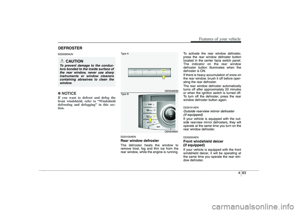
D220100AENRear window defrosterThe defroster heats the window to
remove frost, fog and thin ice from the
rear window, while the engine is running.To activate the rear window defroster,
press the rear window defroster button
located in the center facia switch panel.
The indicator on the rear window
defroster button illuminates when the
defroster is ON.
If there is heavy accumulation of snow on
the rear window, brush it off before oper-
ating the rear defroster.
The rear window defroster automatically
turns off after approximately 20 minutes
or when the ignition switch is turned off.
To turn off the defroster, press the rear
window defroster button again.
D220101AENOutside rearview mirror defroster
(if equipped)If your vehicle is equipped with the out-
side rearview mirror defrosters, they will
operate at the same time you turn on the
rear window defroster.D220200AENFront windshield deicer
(if equipped)If your vehicle is equipped with the front
windshield deicer, it will be operating at
the same time you operate the rear win-
dow defroster.
CAUTION
To prevent damage to the conduc-
tors bonded to the inside surface of
the rear window, never use sharp
instruments or window cleaners
containing abrasives to clean the
window.
OEN046090OEN046091
Type AType B
DEFROSTER
Page 168 of 440
Features of your vehicle86 4❈
❈
2nd row outlet vents (E)
• The air flow of the 2nd row outlet vents
is controlled by the front climate control
system and delivered through the
inside air duct of the front doors. If the
door is open or not closed completely,
the air flow of the 2nd row outlet vent is
not delivered properly. Make sure the
front doors are closed completely.
The air flow of the 2nd row outlet vents
may be weaker than the instrument
panel vents for the long air duct in the
front doors.
Close the air vents in cold weather. The
air flow of the 2nd row outlet vents may
cool a little during heating operation.
(Use the 2nd row outlet vents during
cooling operation.)
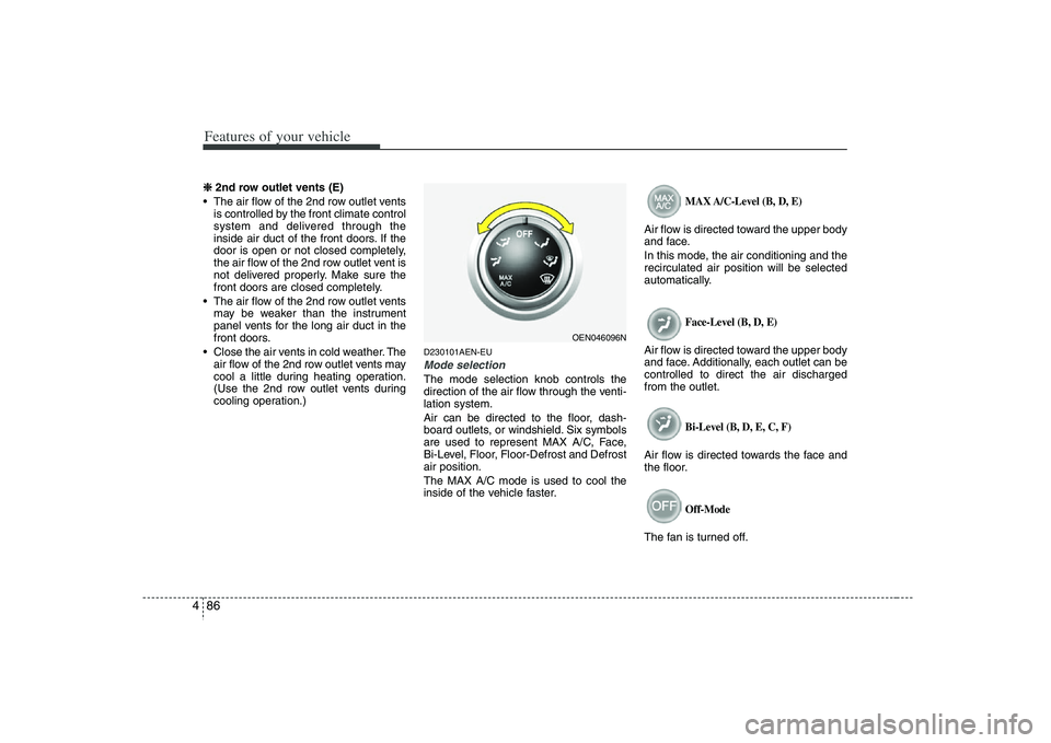
D230101AEN-EUMode selectionThe mode selection knob controls the
direction of the air flow through the venti-
lation system.
Air can be directed to the floor, dash-
board outlets, or windshield. Six symbols
are used to represent MAX A/C, Face,
Bi-Level, Floor, Floor-Defrost and Defrost
air position.
The MAX A/C mode is used to cool the
inside of the vehicle faster.
MAX A/C-Level (B, D, E)
Air flow is directed toward the upper body
and face.
In this mode, the air conditioning and the
recirculated air position will be selected
automatically.
Face-Level (B, D, E)
Air flow is directed toward the upper body
and face. Additionally, each outlet can be
controlled to direct the air discharged
from the outlet.
Bi-Level (B, D, E, C, F)
Air flow is directed towards the face and
the floor.
Off-Mode
The fan is turned off.
OEN046096N
Page 169 of 440
487
Features of your vehicle
Floor-Level (C, F, A, D, E)
Most of the air flow is directed to the
floor, with a small amount of the air being
directed to the windshield and side win-
dow defrosters.
Floor/Defrost-Level (A, C, F, D, E)
Most of the air flow is directed to the floor
and the windshield with a small amount
directed to the side window defrosters.
Defrost-Level (A, D, E)
Most of the air flow is directed to the
windshield with a small amount of air
directed to the side window defrosters.Instrument panel vents
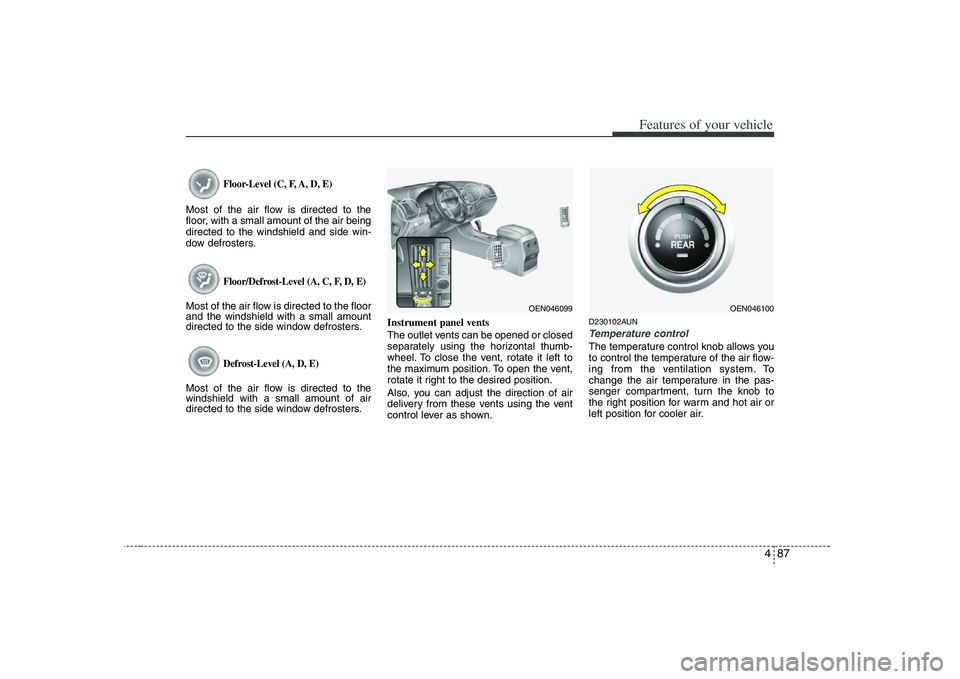
The outlet vents can be opened or closed
separately using the horizontal thumb-
wheel. To close the vent, rotate it left to
the maximum position. To open the vent,
rotate it right to the desired position.
Also, you can adjust the direction of air
delivery from these vents using the vent
control lever as shown.
D230102AUNTemperature controlThe temperature control knob allows you
to control the temperature of the air flow-
ing from the ventilation system. To
change the air temperature in the pas-
senger compartment, turn the knob to
the right position for warm and hot air or
left position for cooler air.
OEN046100
OEN046099
Page 179 of 440

497
Features of your vehicle
D240100AENAutomatic heating and air condi-
tioningThe automatic climate control system is
controlled by simply setting the desired
temperature.
The Full Automatic Temperature Control
(FATC) system automatically controls the
heating and cooling system as follows;
1. Push the AUTO button. The modes,
fan speeds, air intake and air-condi-
tioning will be controlled automatically
by temperature setting.2. Push the TEMP button to set the
desired temperature.
If the temperature is set to the lowest
setting (Lo), the air conditioning sys-
tem will operate continuously.
3. To turn the automatic operation off,
press any button or turn any knob
except the temperature control button.
If you press the mode selection button,
air conditioning button, defrost button
or air intake control button, or turn the
fan speed knob, the selected function
will be controlled manually while other
functions operate automatically.
For your convenience and to improve the
effectiveness of the climate control, use
the AUTO button and set the temperature
to 73°F (23°C).
✽ ✽
NOTICENever place anything over the sensor
located on the instrument panel to
ensure better control of the heating and
cooling system.
OEN046121
OEN046120
Page 181 of 440
499
Features of your vehicle
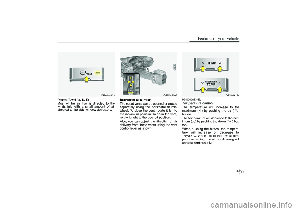
Defrost-Level (A, D, E)
Most of the air flow is directed to the
windshield with a small amount of air
directed to the side window defrosters.Instrument panel vents
The outlet vents can be opened or closed
separately using the horizontal thumb-
wheel. To close the vent, rotate it left to
the maximum position. To open the vent,
rotate it right to the desired position.
Also, you can adjust the direction of air
delivery from these vents using the vent
control lever as shown.
D240202AEN-EUTemperature controlThe temperature will increase to the
maximum (HI) by pushing the up ( )
button.
The temperature will decrease to the min-
imum (Lo) by pushing the down ( ) but-
ton.
When pushing the button, the tempera-
ture will increase or decrease by
1°F/0.5°C. When set to the lowest tem-
perature setting, the air conditioning will
operate continuously.
OEN046123
OEN046099
OEN046124