headlight aiming HYUNDAI XG350 2005 Owners Manual
[x] Cancel search | Manufacturer: HYUNDAI, Model Year: 2005, Model line: XG350, Model: HYUNDAI XG350 2005Pages: 247, PDF Size: 7.28 MB
Page 181 of 247

Engine Compartment .................................................... 6-2
General Checks ............................................................ 6-3
Checking the Engine Oil ............................................... 6-4
Changing the Oil and Filter ............................................ 6-5
Checking and Changing the Engine Coolant ................ 6-6
Spark Plugs .................................................................. 6-8
Changing the Air Cleaner Filter ..................................... 6-9
Checking the Transaxle Fluid .....................................6-11
Checking the Brakes ..................................................6-12
Air Conditioning Care..................................................6-14
Changing the Conoitioner Air Filter
(For Evaporator and Blower Unit) .............................6-15
Checking Drive Belts ..................................................6-17
Checking and Replacing Fuses..................................6-17
Power Steering Fluid Level .........................................6-20
Headlight Aiming Adjustment......................................6-21
Replacement of Light Bulbs ........................................6-22
Bulb Wattage ...............................................................6-31
Junction Box Description............................................6-32
Do-It-Yourself Maintenance
6
6
xgflhma-6.p656/16/04, 2:58 PM 1
Page 201 of 247

6
DO-IT-YOURSELF MAINTENANCE
21
HEADLIGHT AIMING ADJUSTMENT
!
!
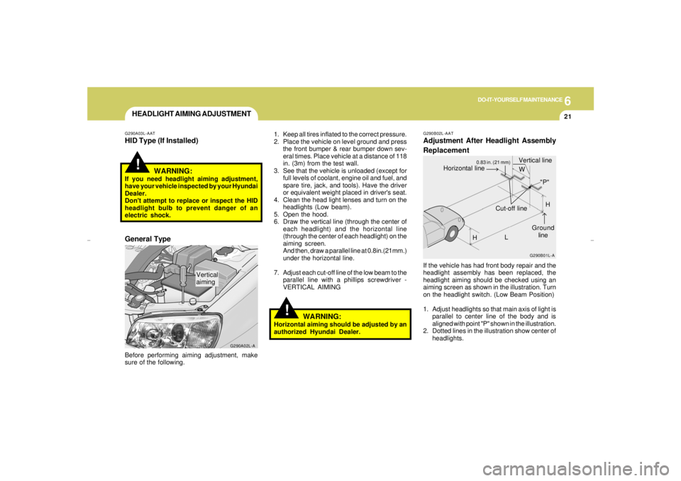
G290A03L-AATHID Type (If Installed)Before performing aiming adjustment, make
sure of the following.
G290A02L-A
Vertical
aiming1. Keep all tires inflated to the correct pressure.
2. Place the vehicle on level ground and press
the front bumper & rear bumper down sev-
eral times. Place vehicle at a distance of 118
in. (3m) from the test wall.
3. See that the vehicle is unloaded (except for
full levels of coolant, engine oil and fuel, and
spare tire, jack, and tools). Have the driver
or equivalent weight placed in driver's seat.
4. Clean the head light lenses and turn on the
headlights (Low beam).
5. Open the hood.
6. Draw the vertical line (through the center of
each headlight) and the horizontal line
(through the center of each headlight) on the
aiming screen.
And then, draw a parallel line at 0.8in.(21mm.)
under the horizontal line.
7. Adjust each cut-off line of the low beam to the
parallel line with a phillips screwdriver -
VERTICAL AIMING
WARNING:
If you need headlight aiming adjustment,
have your vehicle inspected by your Hyundai
Dealer.
Don't attempt to replace or inspect the HID
headlight bulb to prevent danger of an
electric shock.General Type
WARNING:
Horizontal aiming should be adjusted by an
authorized Hyundai Dealer.
G290B02L-AATAdjustment After Headlight Assembly
ReplacementIf the vehicle has had front body repair and the
headlight assembly has been replaced, the
headlight aiming should be checked using an
aiming screen as shown in the illustration. Turn
on the headlight switch. (Low Beam Position)
1. Adjust headlights so that main axis of light is
parallel to center line of the body and is
aligned with point "P" shown in the illustration.
2. Dotted lines in the illustration show center of
headlights.
G290B01L-A
LW
H
HCut-off line
Ground
line
"P" Horizontal lineVertical line
0.83 in. (21 mm)
xgflhma-6.p656/16/04, 2:59 PM 21
Page 244 of 247

10
INDEX
4
J
Jump Starting..................................................................................... 3-3
K
Key .................................................................................................... 1-3
If you lose your keys...................................................................3-13
Positions............................................................................... 2-3 ~ 2-4
L
Lubrication Chart ................................................................................. 9-4
M
Maintenance Intervals
Explanation of scheduled maintenance items...................... 5-7 ~ 5-9
Maintenance under severe usage conditions ................................ 5-6
Scheduled maintenance........................................................ 5-4 ~ 5-5
Service requirements ..................................................................... 5-2
Mirrors
Day-night inside rear view ...........................................................1-61
Outside rearview mirror heater ....................................................1-61
O
Odometer..........................................................................................1-45
Outside rearview mirror ....................................................................1-60 H
Hazard Warning System...................................................................1-50
Headlight Aiming Adjustment ............................................................6-21
Heating and Ventilation ..........................................................1-78 ~ 1-85
Air flow control............................................. 1-80 ~ 1-82, 1-90 ~ 1-91
Air intake control ............................................................... 1-79 ~ 1-80
Bi-level heating ............................................................................1-83
Fan speed control ............................................................... 1-79, 1-88
Temperature control .....................................................................1-82
High-Mounted Rear Stop light ...........................................................1-68
Homelink Mirror................................................................................ 1-62
Hood Release...................................................................................1-72
Horn..................................................................................................1-74
I
Ignition Switch..................................................................................... 2-3
Illuminated Ignition Switch................................................................... 1-4
Instrument Cluster and Indicator Lights............................................1-38
Instrument Panel Light Control (Rheostat).......................................1-52
Intergrated Memory System (I. M. S) ...............................................1-14
Interior Light
Interior light ..................................................................................1-58
Map light ......................................................................................1-58
Personal light...............................................................................1-59
Intermittent Wiper..............................................................................1-49xgflhma-10.p656/16/04, 3:01 PM 4