check engine light INFINITI EX 2013 User Guide
[x] Cancel search | Manufacturer: INFINITI, Model Year: 2013, Model line: EX, Model: INFINITI EX 2013Pages: 498, PDF Size: 2.5 MB
Page 101 of 498

2-30Instruments and controls
5. Confirm that the security indicator lightcomes on. The security indicator light
stays on for about 30 seconds. The
vehicle security system is now pre-
armed. After about 30 seconds the
vehicle security system automatically
shifts into the armed phase. The
security light begins to flash once every
approximately 3 seconds. If, during this
30-second pre-arm time period, the
door is unlocked, or the ignition switch
is pushed to ACC or ON, the system will
not arm.
Even when the driver and/or passengers
are in the vehicle, the system will activate
with all doors, hood, and lift gate locked
with the ignition switch in the LOCK
position. When pushing the ignition switch
to the ACC or ON position, the system will
be released.
Vehicle security system activation
The vehicle security system will give the
following alarm:
. The headlights blink and the horn
sounds intermittently.
. The alarm automatically turns off after
approximately 50 seconds. However,
the alarm reactivates if the vehicle is tampered with again.
The alarm is activated by:
. Unlocking the door or opening the lift
gate without using the button on the
Intelligent Key, the door handle request
switch or the mechanical key. (Even if
the door is opened by releasing the
door inside lock knob, the alarm will
activate.)
. Opening the hood.
How to stop an activated alarm
The alarm will stop when a door is
unlocked by pushing the unlock button
on the Intelligent Key, the door handle
request switch or using the mechanical
key, or when the ignition switch is pushed
to the ACC or ON position.
If the system does not operate as de-
scribed above, have it checked by an
INFINITI retailer.
INFINITI VEHICLE IMMOBILIZER
SYSTEM
The INFINITI Vehicle Immobilizer System
will not allow the engine to start without
the use of the registered Intelligent Key.
Never leave these keys in the vehicle.
FCC Notice:
For USA:
This device complies with Part 15 of the
FCC Rules. Operation is subject to the
following two conditions: (1) This device
may not cause harmful interference, and
(2) this device must accept any interfer-
ence received, including interference that
may cause undesired operation.
NOTE:
Changes or modifications not expressly
approved by the party responsible for
compliance could void the user’s authority
to operate the equipment.
For Canada:
This device complies with RSS-210 of
Industry Canada. Operation is subject to
the following two conditions: (1) this
device may not cause interference, and
(2) this device must accept any interfer-
ence, including interference that may
Page 109 of 498

2-38Instruments and controls
the number of occupants in the vehicle, the
load the vehicle is carrying and the road
conditions.
If the AFS OFF indicator light blinks after
the ignition switch has been pushed to the
ON position, this may indicate that the AFS
is not functioning properly. Have the
system checked by an INFINITI retailer.
When the engine is started, the headlights
will vibrate to check the system condition.
This is not a malfunction.
SIC3270
SIC3628
Instrument brightness control
The instrument brightness control switch
can be operated when the ignition switch
is in the ON position. When the switch is
operated, the dot matrix liquid crystal
display switches to the brightness adjust-
ment mode.
Push the upper switch
*Ato brighten the
instrument panel lights. The bar
*1moves
to the + side. When reaching the maximum
brightness, “MAX”appears on the display
*2.
Push the lower switch
*Bto dim the
instrument panel lights. The bar
*1moves
Page 152 of 498
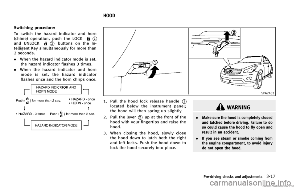
Switching procedure:
To switch the hazard indicator and horn
(chime) operation, push the LOCK
*1
and UNLOCK*2buttons on the In-
telligent Key simultaneously for more than
2 seconds.
. When the hazard indicator mode is set,
the hazard indicator flashes 3 times.
. When the hazard indicator and horn
mode is set, the hazard indicator
flashes once and the horn chirps once.
SPA2452
1. Pull the hood lock release handle*1
located below the instrument panel;
the hood will then spring up slightly.
2. Pull the lever
*2up at the front of the
hood with your fingertips and raise the
hood.
3. When closing the hood, slowly close the hood down to latch both the right
and left locks. Push the hood down to
lock the hood securely into place.
WARNING
. Make sure the hood is completely closed
and latched before driving. Failure to do
so could cause the hood to fly open and
result in an accident.
. If you see steam or smoke coming from
the engine compartment, to avoid injury
do not open the hood.
Pre-driving checks and adjustments3-17
HOOD
Page 154 of 498
SPA1562A
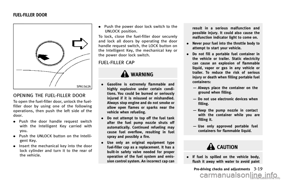
OPENING THE FUEL-FILLER DOOR
To open the fuel-filler door, unlock the fuel-
filler door by using one of the following
operations, then push the left side of the
door.
.Push the door handle request switch
with the Intelligent Key carried with
you.
. Push the UNLOCK button on the Intelli-
gent Key.
. Insert the mechanical key into the door
lock cylinder and turn it to the rear of
the vehicle. .
Push the power door lock switch to the
UNLOCK position.
To lock, close the fuel-filler door securely
and lock all doors by operating the door
handle request switch, the LOCK button on
the Intelligent Key, the mechanical key or
the power door lock switch.
FUEL-FILLER CAP
WARNING
. Gasoline is extremely flammable and
highly explosive under certain condi-
tions. You could be burned or seriously
injured if it is misused or mishandled.
Always stop engine and do not smoke or
allow open flames or sparks near the
vehicle when refueling.
. Do not attempt to top off the fuel tank
after the fuel pump nozzle shuts off
automatically. Continued refueling may
cause fuel overflow, resulting in fuel
spray and possibly a fire.
. Use only an original equipment type
fuel-filler cap as a replacement. It has a
built-in safety valve needed for proper
operation of the fuel system and emis-
sion control system. An incorrect cap can result in a serious malfunction and
possible injury. It could also cause the
malfunction indicator light to come on.
. Never pour fuel into the throttle body to
attempt to start your vehicle.
. Do not fill a portable fuel container in
the vehicle or trailer. Static electricity
can cause an explosion of flammable
liquid, vapor or gas in any vehicle or
trailer. To reduce the risk of serious
injury or death when filling portable fuel
containers:—Always place the container on the
ground when filling.
—Do not use electronic devices whenfilling.
—Keep the pump nozzle in contactwith the container while you are
filling it.
—Use only approved portable fuelcontainers for flammable liquid.
CAUTION
. If fuel is spilled on the vehicle body,
flush it away with water to avoid paint
Pre-driving checks and adjustments3-19
FUEL-FILLER DOOR
Page 164 of 498

Selecting the memorized position
1. Move the selector lever to the P (Park)position.
2. Use one of the following methods to move the driver’ s seat, the outside
mirrors and the steering wheel.
.Push the ignition switch to the ON position and push the memory
switch (1 or 2) fully for at least 1
second.
.Within 45 seconds of opening thedriver’ s door, push the memory
switch (1 or 2) fully for at least 1
second.
The driver’s seat, steering column and
outside mirrors will move to the mem-
orized position or to the exit position
when the entry/exit function is set to
active with the indicator light flashing,
and then the light will stay on for
approximately 5 seconds.
SYSTEM OPERATION
The automatic drive positioner system will
not work or will stop operating under the
following conditions:
. When the vehicle speed is above 4 MPH
(7 km/h). .
When the adjusting switch for the
driver’s seat and steering column is
turned on while the automatic drive
positioner is operating.
. When the memory switch 1 or 2 is not
pushed for at least 1 second.
. When the seat, steering column and
outside mirrors have already been
moved to the memorized position.
. When no position is stored in the
memory switch.
. When the engine is started while
moving the automatic drive positioner.
. When the AT selector lever is moved
from the P (Park) position to any other
position. (However, it will not be
canceled if the switch is pushed while
the seat and steering column are
returning to the previous positions
(entry/exit function).)
. When the driver’s door remains open
for more than 45 seconds and the
ignition switch is not in the ON posi-
tion.
. The seat synchronization function is
automatically disabled if the outside
mirrors or steering wheel reaches its
maximum adjustment. .
The seat synchronization function will
not operate if the seat is adjusted over
one of the following maximum thresh-
olds:
— Seat sliding: 3.0 in (76 mm)
— Seatback reclining: 9.1 degrees
— Seat lifter (rear side): 0.8 in (20 mm)
Pre-driving checks and adjustments3-29
Page 323 of 498
5-12Starting and driving
SSD0785
INTELLIGENT KEY BATTERY DIS-
CHARGE
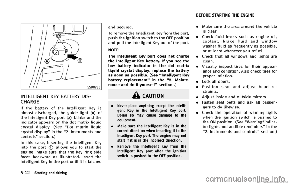
If the battery of the Intelligent Key is
almost discharged, the guide light
*Bof
the Intelligent Key port
*Ablinks and the
indicator appears on the dot matrix liquid
crystal display. (See “Dot matrix liquid
crystal display” in the“2. Instruments and
controls” section.)
In this case, inserting the Intelligent Key
into the port
*1allows you to start the
engine. Make sure that the key ring side
faces backward as illustrated. Insert the
Intelligent Key in the port until it is latched and secured.
To remove the Intelligent Key from the port,
push the ignition switch to the OFF position
and pull the Intelligent Key out of the port.
NOTE:
The Intelligent Key port does not charge
the Intelligent Key battery. If you see the
low battery indicator in the dot matrix
liquid crystal display, replace the battery
as soon as possible. (See
“Intelligent Key
battery replacement” in the“8. Mainte-
nance and do-it-yourself” section .)
CAUTION
.Never place anything except the Intelli-
gent Key in the Intelligent Key port.
Doing so may cause damage to the
equipment.
. Make sure the Intelligent Key is in the
correct direction when inserting it to the
Intelligent Key port. The engine may not
start if it is in the incorrect direction.
. Remove the Intelligent Key from the
Intelligent Key port after the ignition
switch is pushed to the OFF position.
.Make sure the area around the vehicle
is clear.
. Check fluid levels such as engine oil,
coolant, brake fluid and window
washer fluid as frequently as possible,
or at least whenever you refuel.
. Check that all windows and lights are
clean.
. Visually inspect tires for their appear-
ance and condition. Also check tires for
proper inflation.
. Lock all doors.
. Position seat and adjust head re-
straints.
. Adjust inside and outside mirrors.
. Fasten seat belts and ask all passen-
gers to do likewise.
. Check the operation of warning lights
when the ignition switch is pushed to
the ON position. (See “Warning/indica-
tor lights and audible reminders” in the
“2. Instruments and controls” section.)
BEFORE STARTING THE ENGINE
Page 331 of 498
5-20Starting and driving
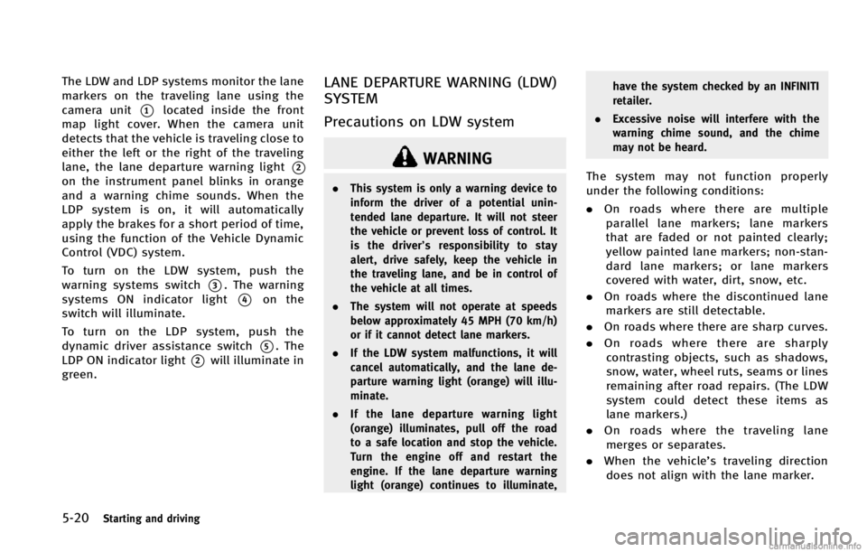
The LDW and LDP systems monitor the lane
markers on the traveling lane using the
camera unit
*1located inside the front
map light cover. When the camera unit
detects that the vehicle is traveling close to
either the left or the right of the traveling
lane, the lane departure warning light
*2
on the instrument panel blinks in orange
and a warning chime sounds. When the
LDP system is on, it will automatically
apply the brakes for a short period of time,
using the function of the Vehicle Dynamic
Control (VDC) system.
To turn on the LDW system, push the
warning systems switch
*3. The warning
systems ON indicator light
*4on the
switch will illuminate.
To turn on the LDP system, push the
dynamic driver assistance switch
*5. The
LDP ON indicator light
*2will illuminate in
green.
LANE DEPARTURE WARNING (LDW)
SYSTEM
Precautions on LDW system
WARNING
. This system is only a warning device to
inform the driver of a potential unin-
tended lane departure. It will not steer
the vehicle or prevent loss of control. It
is the driver’ s responsibility to stay
alert, drive safely, keep the vehicle in
the traveling lane, and be in control of
the vehicle at all times.
. The system will not operate at speeds
below approximately 45 MPH (70 km/h)
or if it cannot detect lane markers.
. If the LDW system malfunctions, it will
cancel automatically, and the lane de-
parture warning light (orange) will illu-
minate.
. If the lane departure warning light
(orange) illuminates, pull off the road
to a safe location and stop the vehicle.
Turn the engine off and restart the
engine. If the lane departure warning
light (orange) continues to illuminate, have the system checked by an INFINITI
retailer.
. Excessive noise will interfere with the
warning chime sound, and the chime
may not be heard.The system may not function properly
under the following conditions:
.On roads where there are multiple
parallel lane markers; lane markers
that are faded or not painted clearly;
yellow painted lane markers; non-stan-
dard lane markers; or lane markers
covered with water, dirt, snow, etc.
. On roads where the discontinued lane
markers are still detectable.
. On roads where there are sharp curves.
. On roads where there are sharply
contrasting objects, such as shadows,
snow, water, wheel ruts, seams or lines
remaining after road repairs. (The LDW
system could detect these items as
lane markers.)
. On roads where the traveling lane
merges or separates.
. When the vehicle’s traveling direction
does not align with the lane marker.
Page 334 of 498
—When driving without normal tireconditions (for example, tire wear,
low tire pressure, installation of
spare tire, tire chains, non-standard
wheels).
—When the vehicle is equipped with
nonoriginal brake parts or suspen-
sion parts.
. If the LDP system malfunctions, it will
cancel automatically. The lane departure
warning light (orange) on the instrument
panel will illuminate.
. If the lane departure warning light
(orange) illuminates, pull off the road
to a safe location and stop the vehicle.
Turn the engine off and restart the
engine. If the warning light (orange)
continues to illuminate, have the LDP
system checked by an INFINITI retailer.
. Excessive noise will interfere with the
warning chime sound, and the chime
may not be heard.
The functions of the LDP system (warning
and brake control assist) may or may not
operate properly under the following con-
ditions: .
On roads where there are multiple
parallel lane markers; lane markers
that are faded or not painted clearly;
yellow painted lane markers; non-stan-
dard lane markers; or lane markers
covered with water, dirt, snow, etc.
. On roads where discontinued lane
markers are still detectable.
. On roads where there are sharp curves.
. On roads where there are sharply
contrasting objects, such as shadows,
snow, water, wheel ruts, seams or lines
remaining after road repairs. (The LDP
system could detect these items as
lane markers.)
. On roads where the traveling lane
merges or separates.
. When the vehicle’s traveling direction
does not align with the lane marker.
. When traveling close to the vehicle in
front of you, which obstructs the lane
camera unit detection range.
. When rain, snow or dirt adheres to the
windshield in front of the lane camera
unit.
. When the headlights are not bright due
to dirt on the lens or if the aiming is not
adjusted properly. .
When strong light enters the lane
camera unit. (For example, the light
directly shines on the front of the
vehicle at sunrise or sunset.)
. When a sudden change in brightness
occurs. (For example, when the vehicle
enters or exits a tunnel or under a
bridge.)
While the LDP system is operating, you
may hear a sound of brake operation. This
is normal and indicates that the LDP
system is operating properly.
Starting and driving5-23
Page 344 of 498

SSD1037
Entering from the side
The BSW indicator light illuminates if a
vehicle enters the detection zone from
either side.
NOTE:
The radar sensors may not detect a vehicle
which is traveling at about the same speed
as your vehicle when it enters the detec-
tion zone.
SSD1038
If the driver activates the turn signal, then
the BSW indicator light flashes and a
chime will sound twice.
NOTE:
If the driver activates the turn signal
before a vehicle enters the detection zone,
the BSW indicator light will flash but no
chime will sound when another vehicle is
detected.
BSW temporarily not available
When radar blockage is detected, the BSW
system will be turned off automatically, a
beep will sound and the BSW system
warning light will blink. The BSW systemis not available until the condition no
longer exists.
The radar sensors may be blocked by
temporary ambient conditions such as
splashing water, mist or fog. The blocked
condition may also be caused by objects
such as ice, frost or dirt obstructing the
radar sensors.
Action to take:
When the above condition no longer exists,
the BSW system will resume automatically.
If the warning light continues to blink, have
the BSW system checked by an INFINITI
retailer.
BSW MALFUNCTION
When the BSW system malfunctions, it will
be turned off automatically, a beep will
sound and the BSW system warning light
will illuminate.
Action to take:
Stop the vehicle in a safe location, turn the
engine off and restart the engine.
If the warning light continues to illuminate,
have the BSW system checked by an
INFINITI retailer.
Starting and driving5-33
Page 356 of 498

4. Indicates your vehicle
5. Set vehicle speed indicator:Indicates the set vehicle speed.
For Canadian models, the speed is
displayed in km/h.
6. Intelligent Cruise Control system warn- ing light (orange):
The light comes on if there is a
malfunction in the ICC system.
SSD0607
When the ignition switch is pushed to the
ON position, the indicators come on as
illustrated to check for a burned-out bulb,
and it turns off when the engine is started.
SSD0901
Operating vehicle-to-vehicle dis-
tance control mode
To turn on the cruise control, quickly push
and release the MAIN switch
*Aon. The
cruise indicator light, set distance indicator
and set vehicle speed indicator come on
and in a standby state for setting.
Starting and driving5-45