battery INFINITI EX 2013 Owner's Manual
[x] Cancel search | Manufacturer: INFINITI, Model Year: 2013, Model line: EX, Model: INFINITI EX 2013Pages: 498, PDF Size: 2.5 MB
Page 17 of 498

0-10Illustrated table of contents
SSI0388
VQ37VHR ENGINE
1. Fuse/fusible link holder (P.8-22)
2. Battery (P.8-15)
3. Radiator filler cap (P.8-8)
4. Engine oil dipstick (P.8-10)
5. Engine oil filler cap (P.8-10)6. Brake fluid reservoir (P.8-13)
7. Window washer fluid reservoir
(P.8-14)
8. Power steering fluid reservoir (P.8-13)
9. Air cleaner (P.8-19)
10. Drive belts (P.8-17) 11. Coolant reservoir (P.8-8)
ENGINE COMPARTMENT
Page 22 of 498

FRONT SEATS
Front power seat adjustment
Operating tips:
.The power seat motor has an auto-reset
overload protection circuit. If the motor
stops during operation, wait 30 sec-
onds, then reactivate the switch.
. Do not operate the power seat switch
for a long period of time when the
engine is off. This will discharge the
battery.
See “Automatic drive positioner” in the“3.
Pre-driving checks and adjustments” sec-
tion for the seat position memory function
(if so equipped).
CAUTION
When adjusting the seat positions, be sure
not to contact any moving parts to avoid
possible injuries and/or damages.
SSS1051
Forward and backward:
Moving the switch
*1forward or backward
will slide the seat forward or backward to
the desired position.
Reclining:
Move the recline switch
*2backward until
the desired angle is obtained. To bring the
seatback forward again, move the switch
*2forward.
The reclining feature allows adjustment of
the seatback for occupants of different
sizes for added comfort and to help obtain
proper seat belt fit. (See “Precautions on
seat belt usage ”later in this section.) Also, the seatback can be reclined to allow
occupants to rest when the vehicle is
stopped and the transmission is in the P
(Park) position.
Safety
—Seats, seat belts and supplemental restraint system1-3
Page 93 of 498

2-22Instruments and controls
INDICATORS FOR OPERATION
1. Engine start operation indicator
This indicator appears when the selector
lever is in the P (Park) position.
This indicator means that the engine will
start by pushing the ignition switch with
the brake pedal depressed.
2. Intelligent Key insertion indicator
This indicator appears when the Intelligent
Key needs to be inserted into the Intelli-
gent Key port. (For example, the Intelligent
Key battery is discharged.)
If this indicator appears, insert the Intelli-
gent Key into the Intelligent Key port in the
correct direction. (See“Push-button igni-
tion switch” in the“5. Starting and driving”
section.)
3. Intelligent Key removal indicator
This indicator appears when the driver’s
door is opened with the ignition switch in
the OFF or LOCK position and the Intelli-
gent Key placed in the Intelligent Key port.
A key reminder chime also sounds.
If this indicator appears, remove the
Intelligent Key from the Intelligent Key port
and take it with you when leaving the vehicle.
4. NO KEY warning
This warning appears in either of the
following conditions.
No key inside the vehicle:
The warning appears when the door is
closed with the Intelligent Key left outside
the vehicle and the ignition switch in the
ACC or ON position. Make sure that the
Intelligent Key is inside the vehicle.
Unregistered Intelligent Key:
The warning appears when the ignition
switch is pushed from the LOCK position
and the Intelligent Key cannot be recog-
nized by the system. You cannot start the
engine with an unregistered key. Use the
registered Intelligent Key.
See
“Intelligent Key system” in the“3. Pre-
driving checks and adjustments” section
for more details.
5. SHIFT “P”warning
This warning appears when the ignition
switch is pushed to stop the engine with
the selector lever in any position except
the P (Park) position.
If this warning appears, move the selector lever to the P (Park) position or push the
ignition switch to the ON position.
An inside warning chime will also sound.
(See
“Intelligent Key system” in the“3.
Pre-driving checks and adjustments” sec-
tion.)
6. “PUSH” warning
This warning appears when the selector
lever is moved to the P (Park) position with
the ignition switch in the ACC position after
the SHIFT “P”warning appears.
To push the ignition switch to the OFF
position, perform the following procedure:
SHIFT “P”warning ?(Move the selector
lever to “P”)?PUSH warning ?(Push the
ignition switch ?ignition switch position
is turned to ON) ?PUSH warning ?(Push
the ignition switch ?ignition switch
position is turned to OFF)
7. Intelligent Key battery discharge
indicator
This indicator appears when the Intelligent
Key battery is running out of power.
If this indicator appears, replace the
battery with a new one. (See “Intelligent
Key battery replacement” in the“8. Main-
tenance and do-it-yourself” section.)
Page 108 of 498

Battery saver system
A chime will sound when the driver side
door is opened with the light switch in the
orposition and the ignition switch
in the ACC, OFF or LOCK position.
When the headlight switch is in the
orposition while the ignition switch is in
the ON position, the lights will automati-
cally turn off within a period of time after
the ignition switch has been pushed to the
OFF position.
When the headlight switch remains in the
orposition after the lights
automatically turn off, the lights will turn
on when the ignition switch is pushed to
the ON position.
CAUTION
. When you turn on the headlight switch
again after the lights automatically turn
off, the lights will not turn off auto-
matically. Be sure to turn the light
switch to the OFF position when you
leave the vehicle for extended periods of
time, otherwise the battery will be
discharged. .
Never leave the light switch on when the
engine is not running for extended
periods of time even if the headlights
turn off automatically.
Daytime running light system (Ca-
nada only)
The daytime running lights automatically
illuminate when the engine is started with
the parking brake released. The daytime
running lights operate with the headlight
switch in the OFF position or in the
position. Turn the headlight switch to theposition for full illumination when
driving at night.
If the parking brake is applied before the
engine is started, the daytime running
lights do not illuminate. The daytime
running lights illuminate once the parking
brake is released. The daytime running
lights will remain on until the ignition
switch is pushed to the OFF position.
WARNING
When the daytime running light system is
active, tail lights on your vehicle are not on.
It is necessary at dusk to turn on your headlights. Failure to do so could cause an
accident injuring yourself and others.
Adaptive Front lighting System
(AFS) (if so equipped)
The Adaptive Front lighting System (AFS)
will automatically adjust the headlights
(low beam) toward the turning direction to
improve the driver’s view. When the head-
light switch is ON and the driver operates
the steering wheel in a turn, the AFS
system will be activated.
The AFS will operate:
.
when the headlight switch is ON.
. when the selector lever is in any
position other than P (Park) or R
(Reverse).
. when the vehicle is driven at above 16
MPH (25 km/h) for the left-side head-
light. Note that the right-side low beam
headlight will swivel but the left side
will not swivel when the vehicle is at a
stop and the steering wheel is turned.
The vehicle must attain a speed above
16 MPH (25 km/h) before AFS activates
the left-side headlight.
AFS will also adjust the headlight to a
proper axis automatically, depending on
Instruments and controls2-37
Page 111 of 498

2-40Instruments and controls
SIC3629
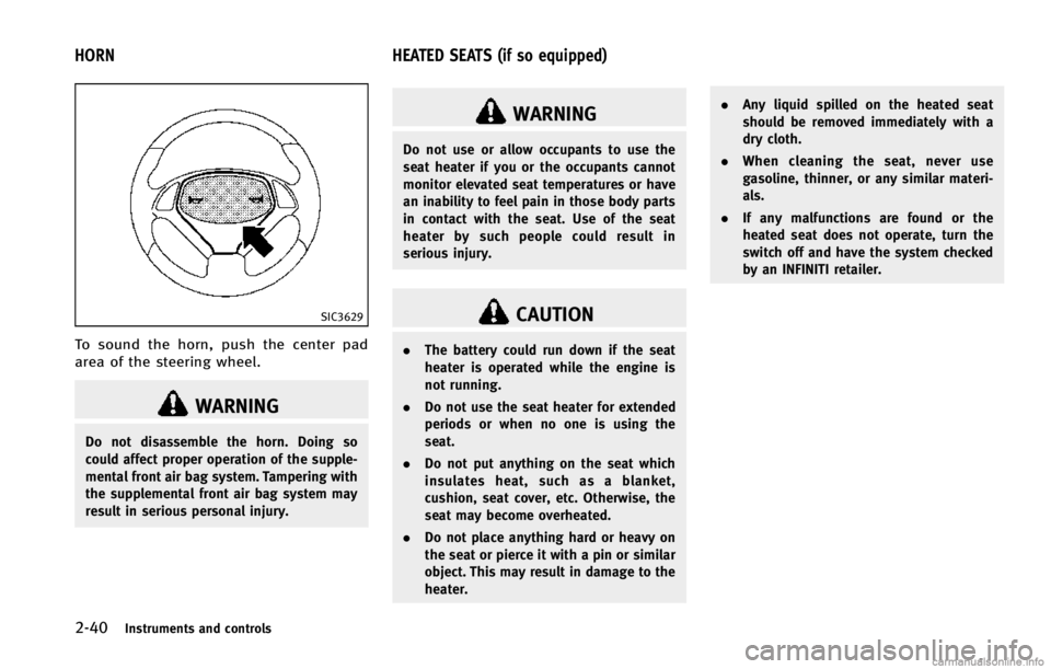
To sound the horn, push the center pad
area of the steering wheel.
WARNING
Do not disassemble the horn. Doing so
could affect proper operation of the supple-
mental front air bag system. Tampering with
the supplemental front air bag system may
result in serious personal injury.
WARNING
Do not use or allow occupants to use the
seat heater if you or the occupants cannot
monitor elevated seat temperatures or have
an inability to feel pain in those body parts
in contact with the seat. Use of the seat
heater by such people could result in
serious injury.
CAUTION
.The battery could run down if the seat
heater is operated while the engine is
not running.
. Do not use the seat heater for extended
periods or when no one is using the
seat.
. Do not put anything on the seat which
insulates heat, such as a blanket,
cushion, seat cover, etc. Otherwise, the
seat may become overheated.
. Do not place anything hard or heavy on
the seat or pierce it with a pin or similar
object. This may result in damage to the
heater. .
Any liquid spilled on the heated seat
should be removed immediately with a
dry cloth.
. When cleaning the seat, never use
gasoline, thinner, or any similar materi-
als.
. If any malfunctions are found or the
heated seat does not operate, turn the
switch off and have the system checked
by an INFINITI retailer.
HORN HEATED SEATS (if so equipped)
Page 116 of 498

The power outlet is used for powering
electrical accessories such as cellular
telephones.
CAUTION
.The outlet and plug may be hot during or
immediately after use.
. Do not use with accessories that exceed
a 12 volt, 120W (10A) power draw. Do
not use double adapters or more than
one electrical accessory.
. Use power outlet with the engine run-
ning to avoid discharging the vehicle
battery.
. Avoid using power outlet when the air
conditioner, headlights or rear window
defroster is on.
. This power outlet is not designed for use
with a cigarette lighter unit.
. Push the plug in as far as it will go. If
good contact is not made, the plug may
overheat or the internal temperature
fuse may blow.
. Before inserting or disconnecting a plug,
be sure the electrical accessory being
used is turned OFF. .
When not in use, be sure to close the
cap. Do not allow water or any liquid to
contact the outlet.
CUP HOLDERS
CAUTION
.Avoid abrupt starting and braking when
the cup holder is being used to prevent
spilling the drink. If the liquid is hot, it
can scald you or your passenger.
. Use only soft cups in the cup holder.
Hard objects can injure you in an
accident.
Instruments and controls2-45
STORAGE
Page 127 of 498

2-56Instruments and controls
switch.
Depending on the environment or driving
conditions, the auto reverse function may
be activated if an impact or load similar to
something being caught in the moonroof
occurs.
If the moonroof does not operate
If the moonroof does not operate properly,
perform the following procedure to initi-
alize the moonroof operation system.
1. If the moonroof is open, close it fully byrepeatedly pushing the CLOSE
*1side
of the moonroof switch.
2. Push and hold the CLOSE
*1side of
the moonroof switch to tilt the moon-
roof up.
3. Release the moonroof switch after the moonroof moves slightly up and down.
4. Push and hold the OPEN
*2side of the
moonroof switch to fully tilt the moon-
roof down.
5. Check if the moonroof switch operates normally.
If the moonroof does not operate properly
after performing the procedure above, have
your vehicle checked by an INFINITI retailer.
SIC3642
To activate or deactivate the welcome light
function, perform the following procedure.
Note that the function is set to disabled as
the factory default setting.
1. Push the ignition switch to the ON position.
2. Open the driver’s side door.
3. Within 20 seconds after the ignition switch is pushed to the ON position,
push the door open request switch on
the driver’s side door handle for more
than 5 seconds with the driver’s door
open. 4. A chime sounds when the setting is
completed.
Once the welcome light function is active,
the puddle light
*Aand the passenger
cabin illumination will illuminate when you
approach the vehicle with the Intelligent
Key (within approximately 3.3 feet (1 m) of
the antenna built inside the door handles)
and the following conditions are met.
. All doors are closed and locked.
. The ignition switch is in the LOCK or OFF
position.
. The Intelligent Key is outside the
vehicle.
. The puddle light operates within a set
duration.
The welcome light function will be deacti-
vated automatically if it does not operate
within a set duration to prevent battery
discharge. Note that the duration is set to
14 days.
WELCOME LIGHT
Page 129 of 498

2-58Instruments and controls
.ignition switch is switched to the LOCK
position
— remain on for about 15 seconds.
. doors are unlocked by pushing the
UNLOCK button on the Intelligent Key
or door handle request switch with the
ignition switch in the LOCK position
— remain on for about 15 seconds.
. any door is opened and then closed
with the ignition switch in the LOCK
position
— remain on for about 15 seconds.
. any door is opened with the ignition
switch in the ACC or ON position
— remain on while the door is opened.
When the door is closed, the lights
go off.
The lights will also turn off after a period
of time when the lights remain illuminated
after the ignition switch has been pushed
to the OFF or LOCK position to prevent the
battery from becoming discharged.
When the auto interior illumination is set
to the OFF position (see “Vehicle informa-
tion and settings” in the“4. Monitor,
climate, audio, phone and voice recogni-
tion systems” section), the lights will
illuminate under the following condition: .
any door is opened with the ignition
switch in any position
— remain on while the door is opened.
When the door is closed, the lights
go off.
OFF position
When the switch is in the OFF position*3,
the lights will not illuminate, regardless of
the condition.
CAUTION
Do not use for extended periods of time with
the engine stopped. This could result in a
discharged battery.
SIC3869
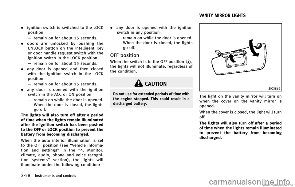
The light on the vanity mirror will turn on
when the cover on the vanity mirror is
opened.
When the cover is closed, the light will turn
off.
The lights will also turn off after a period
of time when the lights remain illuminated
to prevent the battery from becoming
discharged.
VANITY MIRROR LIGHTS
Page 130 of 498

SIC2925
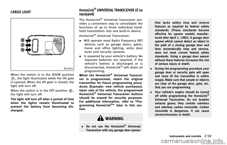
When the switch is in the DOOR position
*A, the light illuminates while the lift gate
is opened. When the lift gate is closed, the
light will turn off.
When the switch is in the OFF position
*B,
the light will turn off.
The light will turn off after a period of time
when the lights remain illuminated to
prevent the battery from becoming dis-
charged. The HomeLink
®Universal Transceiver pro-
vides a convenient way to consolidate the
functions of up to three individual hand-
held transmitters into one built-in device.
HomeLink
®Universal Transceiver:
. Will operate most Radio Frequency (RF)
devices such as garage doors, gates,
home and office lighting, entry door
locks and security systems.
. Is powered by your vehicle’s battery. No
separate batteries are required. If the
vehicle’s battery is discharged or is
disconnected, HomeLink
®will retain all
programming.
When the HomeLink
®Universal Transcei-
ver is programmed, retain the original
transmitter for future programming proce-
dures (Example: new vehicle purchases).
Upon sale of the vehicle, the programmed
HomeLink
®Universal Transceiver buttons
should be erased for security purposes.
For additional information, refer to “Pro-
gramming HomeLink
®” later in this sec-
tion.
WARNING
. Do not use the HomeLink®Universal
Transceiver with any garage door opener that lacks safety stop and reverse
features as required by federal safety
standards. (These standards became
effective for opener models manufac-
tured after April 1, 1982). A garage door
opener which cannot detect an object in
the path of a closing garage door and
then automatically stop and reverse,
does not meet current federal safety
standards. Using a garage door opener
without these features increases the risk
of serious injury or death.
. During the programming procedure your
garage door or security gate will open
and close (if the transmitter is within
range). Make sure that people or objects
are clear of the garage door, gate, etc.
that you are programming.
. Your vehicle’s engine should be turned
off while programming the HomeLink
®
Universal Transceiver. Do not breathe
exhaust gases; they contain colorless
and odorless carbon monoxide. Carbon
monoxide is dangerous. It can cause
unconsciousness or death.
Instruments and controls2-59
CARGO LIGHT HomeLink®UNIVERSAL TRANSCEIVER (if so
equipped)
Page 131 of 498

2-60Instruments and controls
PROGRAMMING HomeLink®
If you have any questions or are having
difficulty programming your HomeLink®
buttons, refer to the HomeLink®web site
at: www.homelink.com or call 1-800-355-
3515.
NOTE:
It is also recommended that a new battery
be placed in the hand-held transmitter of
the device being programmed to
HomeLink
®for quicker programming and
accurate transmission of the radio-fre-
quency.
1. Position the end of your hand-held transmitter 1-3 in (26-76 mm) away
from the HomeLink
®surface, keeping
the HomeLink®indicator light*1in
view.
JVI0428X
2. Using both hands, simultaneously
press and hold the desired HomeLink®
button and handheld transmitter but-
ton. DO NOT release until the
HomeLink
®indicator light*1flashes
slowly and then rapidly. When the
indicator light flashes rapidly, both
buttons may be released. (The rapid
flashing indicates successful program-
ming.)
NOTE:
Some devices to be programmed may
require you to replace Step 2 with the
cycling procedure noted in the “Pro-
gramming HomeLink
®for Canadian customers and gate openers”
later in
this section.