inflation pressure INFINITI FX 2012 Owners Manual
[x] Cancel search | Manufacturer: INFINITI, Model Year: 2012, Model line: FX, Model: INFINITI FX 2012Pages: 522, PDF Size: 3.51 MB
Page 97 of 522
2-26Instruments and controls
18. Distance Control Assist (DCA)
system switch indicator (if so
equipped)
The indicator is displayed when the Dis-
tance Control Assist (DCA) system switch is
pushed on. When the switch is pushed
again, the indicator disappears. While the
indicator is displayed, the DCA system is
operational. (See“Distance Control Assist
(DCA) system” (P.5-54).)
SIC3281
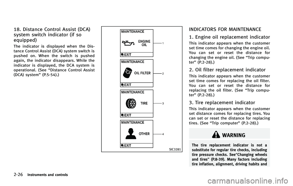
INDICATORS FOR MAINTENANCE
1. Engine oil replacement indicator
This indicator appears when the customer
set time comes for changing the engine oil.
You can set or reset the distance for
changing the engine oil. (See “Trip compu-
ter” (P.2-28).)
2. Oil filter replacement indicator
This indicator appears when the customer
set time comes for replacing the oil filter.
You can set or reset the distance for
replacing the oil filter. (See “Trip compu-
ter” (P.2-28).)
3. Tire replacement indicator
This indicator appears when the customer
set distance comes for replacing tires. You
can set or reset the distance for replacing
tires. (See “Trip computer” (P.2-28).)
WARNING
The tire replacement indicator is not a
substitute for regular tire checks, including
tire pressure checks. See“Changing wheels
and tires” (P.8-39). Many factors including
tire inflation, alignment, driving habits and
Page 329 of 522
5-4Starting and driving
cause a fire.
CAUTION
.Do not use leaded gasoline. Deposits
from leaded gasoline seriously reduce
the three-way catalyst’s ability to help
reduce exhaust pollutants.
. Keep your engine tuned up. Malfunctions
in the ignition, fuel injection, or elec-
trical systems can cause overrich fuel
flow into the three-way catalyst, causing
it to overheat. Do not keep driving if the
engine misfires, or if noticeable loss of
performance or other unusual operating
conditions are detected. Have the vehicle
inspected promptly by an INFINITI retai-
ler.
. Avoid driving with an extremely low fuel
level. Running out of fuel could cause
the engine to misfire, damaging the
three-way catalyst.
. Do not race the engine while warming it
up.
. Do not push or tow your vehicle to start
the engine.
TIRE PRESSURE MONITORING SYS-
TEM (TPMS)
Each tire, including the spare (if provided),
should be checked monthly when cold and
inflated to the inflation pressure recom-
mended by the vehicle manufacturer on the
vehicle placard or tire inflation pressure
label. (If your vehicle has tires of a different
size than the size indicated on the vehicle
placard or tire inflation pressure label, you
should determine the proper tire inflation
pressure for those tires.)
As an added safety feature, your vehicle
has been equipped with a Tire Pressure
Monitoring System (TPMS) that illuminates
a low tire pressure telltale when one or
more of your tires is significantly under-
inflated. Accordingly, when the low tire
pressure telltale illuminates, you should
stop and check your tires as soon as
possible, and inflate them to the proper
pressure. Driving on a significantly under-
inflated tire causes the tire to overheat and
can lead to tire failure. Under-inflation also
reduces fuel efficiency and tire tread life,
and may affect the vehicle’s handling and
stopping ability.
Please note that the TPMS is not a
substitute for proper tire maintenance, and it is the driver’
s responsibility to
maintain correct tire pressure, even if
under-inflation has not reached the level
to trigger illumination of the TPMS low tire
pressure telltale.
Your vehicle has also been equipped with a
TPMS malfunction indicator to indicate
when the system is not operating properly.
The TPMS malfunction indicator is com-
bined with the low tire pressure telltale.
When the system detects a malfunction,
the telltale will flash for approximately one
minute and then remain continuously
illuminated. This sequence will continue
upon subsequent vehicle start-ups as long
as the malfunction exists. When the mal-
function indicator is illuminated, the sys-
tem may not be able to detect or signal low
tire pressure as intended. TPMS malfunc-
tions may occur for a variety of reasons,
including the installation of replacement or
alternate tires or wheels on the vehicle that
prevent the TPMS from functioning prop-
erly. Always check the TPMS malfunction
telltale after replacing one or more tires or
wheels on your vehicle to ensure that the
replacement or alternate tires and wheels
allow the TPMS to continue to function
properly.
Page 330 of 522
Additional information
.The TPMS does not monitor the tire
pressure of the spare tire.
. The TPMS will activate only when the
vehicle is driven at speeds above 16
MPH (25 km/h). Also, this system may
not detect a sudden drop in tire
pressure (for example a flat tire while
driving).
. The low tire pressure warning light does
not automatically turn off when the tire
pressure is adjusted. After the tire is
inflated to the recommended pressure,
the vehicle must be driven at speeds
above 16 MPH (25 km/h) to activate the
TPMS and turn off the low tire pressure
warning light. Use a tire pressure gauge
to check the tire pressure.
. The CHECK TIRE PRESSURE warning also
appears on the dot matrix liquid crystal
display when the low tire pressure
warning light is illuminated and low
tire pressure is detected. The CHECK
TIRE PRESSURE warning turns off when
the low tire pressure warning light
turns off.
The CHECK TIRE PRESSURE warning
does not appear if the low tire pressure
warning light illuminates to indicate a TPMS malfunction.
. Tire pressure rises and falls depending
on the heat caused by the vehicle’s
operation and the outside temperature.
Low outside temperature can lower the
temperature of the air inside the tire
which can cause a lower tire inflation
pressure. This may cause the low tire
pressure warning light to illuminate. If
the warning light illuminates in low
ambient temperature, check the tire
pressure for all four tires.
. You can also check the pressure of all
tires (except the spare tire) on the
display screen. The order of the tire
pressure figures displayed on the
screen does not correspond with the
actual order of the tire position. See
“TIRE PRESSURE information” (P.4-11).
For additional information, see “Low tire
pressure warning light” (P.2-15) and“Tire
Pressure Monitoring System (TPMS)” (P.6-
2).
WARNING
. If the low tire pressure warning light
illuminates or LOW PRESSURE informa-
tion is displayed on the monitor screen while driving, avoid sudden steering
maneuvers or abrupt braking, reduce
vehicle speed, pull off the road to a safe
location and stop the vehicle as soon as
possible. Driving with under-inflated
tires may permanently damage the tires
and increase the likelihood of tire fail-
ure. Serious vehicle damage could occur
and may lead to an accident and could
result in serious personal injury. Check
the tire pressure for all four tires. Adjust
the tire pressure to the recommended
COLD tire pressure shown on the Tire
and Loading Information label to turn
the low tire pressure warning light OFF. If
the light still illuminates while driving
after adjusting the tire pressure, a tire
may be flat. If you have a flat tire,
replace it with a spare tire as soon as
possible. (See
“Flat tire” (P.6-2) for
changing a flat tire.)
. When a spare tire is mounted or a wheel
is replaced, the TPMS will not function
and the low tire pressure warning light
will flash for approximately 1 minute.
The light will remain on after 1 minute.
Contact your INFINITI retailer as soon as
possible for tire replacement and/or
system resetting.
Starting and driving5-5
Page 469 of 522
8-32Maintenance and do-it-yourself
SDI1500B
Cargo light
SDI1839
Vanity mirror lightIf you have a flat tire, see
“Flat tire”(P.6-
2).
TIRE PRESSURE
Tire Pressure Monitoring System
(TPMS)
This vehicle is equipped with the Tire
Pressure Monitoring System (TPMS). It
monitors tire pressure of all tires except
the spare. When the low tire pressure
warning light is lit and the CHECK TIRE
PRESSURE warning appears on the dot
matrix liquid crystal display, one or more
of your tires is significantly under-inflated.
The TPMS will activate only when the
vehicle is driven at speeds above 16 MPH
(25 km/h). Also, this system may not
detect a sudden drop in tire pressure (for
example a flat tire while driving).
For more details, see “Low tire pressure
warning light” (P.2-15),“Tire Pressure
Monitoring System (TPMS)” (P.5-4) and
“Tire Pressure Monitoring System (TPMS)”
(P.6-2).
Tire inflation pressure
Check the pressure of the tires
(including the spare) often and al- ways prior to long distance trips. The
recommended tire pressure specifi-
cations are shown on the Tire and
Loading Information label under the
“Cold Tire Pressure”
heading. The
Tire and Loading Information label is
affixed to the driver side center pillar.
Tire pressures should be checked
regularly because:
.Most tires naturally lose air over time.
.Tires can lose air suddenly whendriven over potholes or other
objects or if the vehicle strikes a
curb while parking.
The tire pressures should be checked
when the tires are cold. The tires are
considered COLD after the vehicle
has been parked for 3 or more hours,
or driven less than 1 mile (1.6 km) at
moderate speeds.
Incorrect tire pressure, including
under inflation, may adversely affect
tire life and vehicle handling.
WHEELS AND TIRES
Page 471 of 522
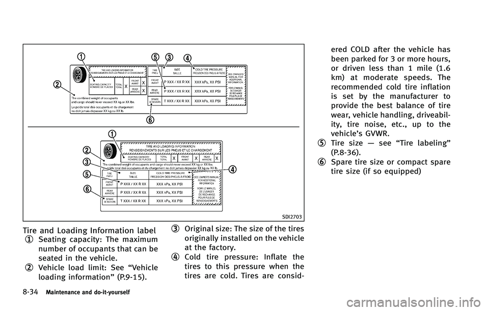
8-34Maintenance and do-it-yourself
SDI2703
Tire and Loading Information label
*1Seating capacity: The maximum
number of occupants that can be
seated in the vehicle.
*2Vehicle load limit: See“Vehicle
loading information” (P.9-15).
*3Original size: The size of the tires
originally installed on the vehicle
at the factory.
*4Cold tire pressure: Inflate the
tires to this pressure when the
tires are cold. Tires are consid- ered COLD after the vehicle has
been parked for 3 or more hours,
or driven less than 1 mile (1.6
km) at moderate speeds. The
recommended cold tire inflation
is set by the manufacturer to
provide the best balance of tire
wear, vehicle handling, driveabil-
ity, tire noise, etc., up to the
vehicle’s GVWR.
*5Tire size
—see “Tire labeling”
(P.8-36).
*6Spare tire size or compact spare
tire size (if so equipped)
Page 472 of 522
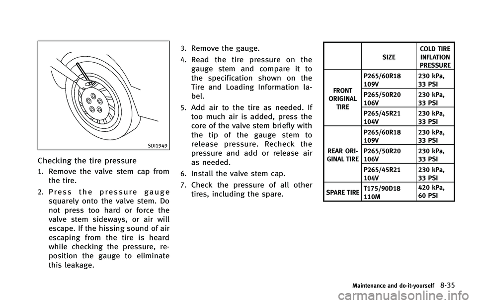
SDI1949
Checking the tire pressure
1.Remove the valve stem cap from
the tire.
2.Press the pressure gauge
squarely onto the valve stem. Do
not press too hard or force the
valve stem sideways, or air will
escape. If the hissing sound of air
escaping from the tire is heard
while checking the pressure, re-
position the gauge to eliminate
this leakage.
3.Remove the gauge.
4.Read the tire pressure on the
gauge stem and compare it to
the specification shown on the
Tire and Loading Information la-
bel.
5.Add air to the tire as needed. If
too much air is added, press the
core of the valve stem briefly with
the tip of the gauge stem to
release pressure. Recheck the
pressure and add or release air
as needed.
6.Install the valve stem cap.
7.Check the pressure of all other
tires, including the spare.
SIZECOLD TIRE
INFLATION
PRESSURE
FRONT
ORIGINAL
TIRE P265/60R18
109V
230 kPa,
33 PSI
P265/50R20
106V 230 kPa,
33 PSI
P265/45R21
104V 230 kPa,
33 PSI
REAR ORI-
GINAL TIRE P265/60R18
109V
230 kPa,
33 PSI
P265/50R20
106V 230 kPa,
33 PSI
P265/45R21
104V 230 kPa,
33 PSI
SPARE TIRE T175/90D18
110M 420 kPa,
60 PSI
Maintenance and do-it-yourself8-35
Page 474 of 522
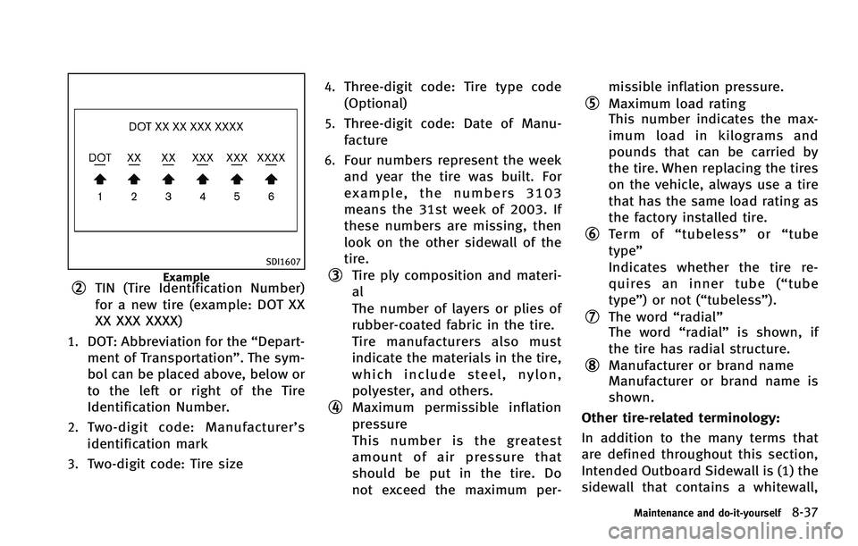
SDI1607
Example*2TIN (Tire Identification Number)
for a new tire (example: DOT XX
XX XXX XXXX)
1.DOT: Abbreviation for the“Depart-
ment of Transportation”. The sym-
bol can be placed above, below or
to the left or right of the Tire
Identification Number.
2.Two-digit code: Manufacturer’ s
identification mark
3.Two-digit code: Tire size
4.Three-digit code: Tire type code
(Optional)
5.Three-digit code: Date of Manu-
facture
6.Four numbers represent the week
and year the tire was built. For
example, the numbers 3103
means the 31st week of 2003. If
these numbers are missing, then
look on the other sidewall of the
tire.
*3Tire ply composition and materi-
al
The number of layers or plies of
rubber-coated fabric in the tire.
Tire manufacturers also must
indicate the materials in the tire,
which include steel, nylon,
polyester, and others.
*4Maximum permissible inflation
pressure
This number is the greatest
amount of air pressure that
should be put in the tire. Do
not exceed the maximum per- missible inflation pressure.
*5Maximum load rating
This number indicates the max-
imum load in kilograms and
pounds that can be carried by
the tire. When replacing the tires
on the vehicle, always use a tire
that has the same load rating as
the factory installed tire.
*6Term of
“tubeless” or“tube
type”
Indicates whether the tire re-
quires an inner tube (“ tube
type”) or not (“tubeless”).
*7The word “radial”
The word “radial”is shown, if
the tire has radial structure.
*8Manufacturer or brand name
Manufacturer or brand name is
shown.
Other tire-related terminology:
In addition to the many terms that
are defined throughout this section,
Intended Outboard Sidewall is (1) the
sidewall that contains a whitewall,
Maintenance and do-it-yourself8-37
Page 479 of 522
8-42Maintenance and do-it-yourself
Wheel balance service should be per-
formed with the wheels off the vehicle.
Spin balancing the wheels on the vehicle
could lead to mechanical damage.
For additional information regarding tires,
refer to“Important Tire Safety Information”
(US) or “Tire Safety Information” (Canada)
in the INFINITI Warranty Information Book-
let.
Care of wheels
See “Cleaning exterior” (P.7-2) for details
about care of the wheels.
Spare tire (TEMPORARY USE ONLY
(T-type) spare tire)
When a spare tire is mounted (TEMPORARY
USE ONLY or conventional), the TPMS will
not function.
Observe the following precautions if the T-
type spare tire must be used, otherwise
your vehicle could be damaged or involved
in an accident.
WARNING
. The T-type spare tire should be used for
emergency use. It should be replaced
with the standard tire at the first opportunity to avoid possible tire or
differential damage.
. Drive carefully while the TEMPORARY
USE ONLY spare tire is installed. Avoid
sharp turns and abrupt braking while
driving.
. Periodically check spare tire inflation
pressure. Always keep the pressure of
the TEMPORARY USE ONLY spare tire at
60 psi (420 kPa, 4.2 bar). Always keep
the pressure of the full size spare tire (if
so equipped) at the recommended pres-
sure for standard tires, as indicated on
the Tire and Loading Information label.
For Tire and Loading Information label
location, see “Tire and Loading Informa-
tion label” in the index of this manual.
. With the TEMPORARY USE ONLY spare
tire installed do not drive your vehicle at
speeds faster than 50 MPH (80 km/h).
. When driving on roads covered with
snow or ice, the TEMPORARY USE ONLY
spare tire should be used on the front
wheels and original tire used on the rear
wheels (drive wheels). Use tire chains
only on the two rear original tires.
. Tire tread of the TEMPORARY USE ONLY
spare tire will wear at a faster rate than the standard tire. Replace the spare tire
as soon as the tread wear indicators
appear.
. Do not use the spare tire on other
vehicles.
. Do not use more than one spare tire at
the same time.
. Do not tow a trailer when the TEMPOR-
ARY USE ONLY spare tire is installed.
CAUTION
.Do not use tire chains on a TEMPORARY
USE ONLY spare tire. Tire chains will not
fit properly and may cause damage to
the vehicle.
. Because the TEMPORARY USE ONLY
spare tire is smaller than the original
tire, ground clearance is reduced. To
avoid damage to the vehicle, do not
drive over obstacles. Also do not drive
the vehicle through an automatic car
wash since it may get caught.
Page 496 of 522
VEHICLE LOAD CAPACITY
Do not exceed the load limit of your
vehicle shown as“The combined
weight of occupants and cargo” on
the Tire and Loading Information
label. Do not exceed the number of
occupants shown as “Seating Capa-
city” on the Tire and Loading In-
formation label.
To get “the combined weight of
occupants and cargo” , add the
weight of all occupants, then add
the total luggage weight. Examples
are shown in the illustration.
Steps for determining correct load
limit
1.Locate the statement “The com-
bined weight of occupants and
cargo should never exceed XXX kg
or XXX lbs” on your vehicle’ s
placard.
2.Determine the combined weight of
the driver and passengers that
will be riding in your vehicle.
3.Subtract the combined weight of
the driver and passengers from
XXX kg or XXX lbs.
4.The resulting figure equals the
available amount of cargo and
luggage load capacity. For exam-
ple, if the XXX amount equals
1400 lbs. and there will be five
150 lb. passengers in your vehi-
cle, the amount of available cargo
and luggage load capacity is 650
lbs. (1400 −750 (5 x 150) = 650
lbs) or (640 −340 (5 x 70) = 300
kg.)
5.Determine the combined weight of
luggage and cargo being loaded
on the vehicle. That weight may
not safely exceed the available
cargo and luggage load capacity
calculated in Step 4.
6.If your vehicle will be towing a
trailer, load from your trailer will
be transferred to your vehicle.
Consult this manual to determine
how this reduces the available cargo and luggage load capacity
of your vehicle.
Before driving a loaded vehicle,
confirm that you do not exceed the
Gross Vehicle Weight Rating (GVWR)
or the Gross Axle Weight Rating
(GAWR) for your vehicle. (See “Mea-
surement of weights” (P.9-19).)
Also check tires for proper inflation
pressures. See the Tire and Loading
Information label.
Technical and consumer information9-17
Page 503 of 522

9-24Technical and consumer information
of the ball.
. Choose the proper class hitch ball
based on the trailer weight.
. The diameter of the threaded shank of
the hitch ball must be matched to the
ball mount hole diameter. The hitch ball
shank should be no more than 1/16
smaller than the hole in the ball mount.
. The threaded shank of the hitch ball
must be long enough to be properly
secured to the ball mount. There should
be at least 2 threads showing beyond
the lock washer and nut.
Sway control device
Sudden maneuvers, wind gusts and buffet-
ing caused by other vehicles can affect
trailer handling. Sway control devices may
be used to help control these affects. If you
choose to use one, contact a reputable
trailer hitch supplier to make sure the sway
control device will work with the vehicle,
hitch, trailer and the trailer’s brake system.
Follow the instructions provided by the
manufacturer for installing and using the
sway control device.
Class I hitch
Class I trailer hitch equipment (receiver,
ball mount and hitch ball) can be used to
tow trailers of a maximum weight of 2,000
lb (907 kg).
Class II hitch
Class II trailer hitch equipment (receiver,
ball mount and hitch ball) can be used to
tow trailers of a maximum weight of 3,500
lb (1,588 kg).
CAUTION
. Special hitches which include frame
reinforcements are required for towing
above 2,000 lb (907 kg). Suitable
genuine INFINITI hitches for pickup
trucks and sport utility vehicles are
available at an INFINITI retailer.
. The hitch should not be attached to or
affect the operation of the impact-
absorbing bumper.
. Do not use axle-mounted hitches.
. Do not modify the vehicle exhaust
system, brake system, etc. to install a
trailer hitch. .
To reduce the possibility of additional
damage if your vehicle is struck from the
rear, where practical, remove the hitch
and/or receiver when not in use. After
the hitch is removed, seal the bolt holes
to prevent exhaust fumes, water or dust
from entering the passenger compart-
ment.
. Regularly check that all trailer hitch
mounting bolts are securely mounted.
Tire pressures
.When towing a trailer, inflate the
vehicle tires to the recommended
cold tire pressure indicated on the
Tire and Loading Information la-
bel.
.Trailer tire condition, size, loadrating and proper inflation pres-
sure should be in accordance with
the trailer and tire manufacturers’
specifications.
Safety chains
Always use a suitable chain between your
vehicle and the trailer. The safety chains
should be crossed and should be attached