wiper washer pump INFINITI FX35 2004 Service Manual
[x] Cancel search | Manufacturer: INFINITI, Model Year: 2004, Model line: FX35, Model: INFINITI FX35 2004Pages: 4449, PDF Size: 99.66 MB
Page 3277 of 4449
IDX-4
ALPHABETICAL INDEX
Electric throttle control actuator ........ EC-415, EC-417,
EC-1077
, EC-1079
Electric throttle control actuator (VK45DE) ..... EM-174
Electric throttle control actuator (VQ35DE) ....... EM-19
Electrical load signal circuit .............. EC-614, EC-1292
Electrical unit ..................................................... PG-77
Electrical units location ...................................... PG-70
Electronic ignition (EI) system ............. EC-34, EC-681
Engine control module (ECM) .......... EC-401, EC-1057
Engine control system diagram and chart ........ EC-29,
EC-676
Engine coolant temperature sensor (ECTS) ... EC-185,
EC-197
, EC-842, EC-855
Engine coolant(VK45DE) .................................. CO-36
Engine coolant(VQ35DE) ................................. CO-11
Engine oil filter replacement ............................. MA-25
Engine oil filter replacement(VQ35DE) ............. MA-18
Engine oil precautions .......................................... GI-8
Engine oil replacement(VQ35DE) ..................... MA-17
Engine oil(VK45DE) ........................................... LU-25
Engine oil(VQ35DE) ............................................ LU-7
Engine removal(VK45DE) ............................... EM-236
Engine removal(VQ35DE) .............................. EM-110
Engine room cover(VK45DE) ......................... EM-168
ETC1 - Wiring diagram .................... EC-418, EC-1080
ETC2 - Wiring diagram .................... EC-425, EC-1087
ETC3 - Wiring diagram .................... EC-429, EC-1091
EVAP canister .................................. EC-646, EC-1323
EVAP canister purge volume control solenoid valve ....
EC-335
, EC-990, EC-1160
EVAP canister vent control valve ...... EC-342, EC-502,
EC-997
, EC-1168
EVAP control system (small leak) diagnosis .. EC-326,
EC-366
, EC-981, EC-1022
EVAP control system pressure sensor ........... EC-349,
EC-352
, EC-358, EC-1004, EC-1007, EC-1014
EVAP control system purge flow monitoring diagnosis
EC-321
, EC-976
EVAP vapor lines inspection ................. MA-20, MA-27
Evaporative emission (EVAP) system ............ EC-643,
EC-1320
Evaporator ..................................................... ATC-155
Exhaust manifold(VK45DE) ............................ EM-178
Exhaust manifold(VQ35DE) .............................. EM-26
Exhaust system ................................................... EX-3
Exhaust system inspection ..................... EX-3, MA-28
Expansion valve ............................................. ATC-156
F
F/FOG - Wiring diagram ..................................... LT-79
F/PUMP - Wiring diagram ................ EC-604, EC-1281
Final drive removal and installation .. FFD-10, RFD-11
Floor trim ............................................................. EI-40
Flow charts ......................................................... GI-27
Fluid temperature sensor (A/T) ........................ AT-139
Fluorescent leak detector .............................. ATC-157
Fog lamp, front .................................................... LT-77
Front axle ............................................. FAX-4, FAX-10
Front brake solenoid valve ................. AT-156, AT-158
Front bumper ...................................................... EI-14
Front door ............................. BL-148, BL-152, GW-76
Front fog lamp .................................................... LT-77
Front passenger air bag .................................. SRS-40
Front seat belt ...................................................... SB-4
Front seat belt pre-tensioner ..... SB-2, SRS-3, SRS-47
Front side air bag ............................................ SRS-41
Front suspension .............................................. FSU-6
Front washer ...................................................... WW-4
Front wiper ......................................................... WW-4
FTTS - Wiring diagram ...... EC-275, EC-280, EC-933,
EC-938
Fuel cut control (at no load high engine speed) EC-35,
EC-683
Fuel filter replacement ......................................... FL-4
Fuel gauge ............................................................ DI-4
Fuel injector and fuel tube(VK45DE) .............. EM-188
Fuel injector and fuel tube(VQ35DE) ................ EM-45
Fuel level sensor EC-384, EC-386, EC-388, EC-1040,
EC-1042
, EC-1044
Fuel line inspection .................................. FL-3, MA-24
Fuel line inspection(VQ35DE) .......................... MA-17
Fuel precautions .......................................... GI-6, GI-7
Fuel pressure check ........................... EC-51, EC-700
Fuel pressure release ......................... EC-51, EC-700
Fuel pump ....................................... EC-603, EC-1280
Fuel pump and gauge .......................................... FL-4
Fuel system ......................................................... FL-3
Fuel tank ............................................................ FL-10
Fuel tank temperature sensor .......... EC-273, EC-279,
EC-931
, EC-937
Fuel tank vacuum relief valve ......... EC-646, EC-1323
FUELB1 - Wiring diagram .. EC-258, EC-267, EC-916,
EC-925
FUELB2 - Wiring diagram .. EC-259, EC-268, EC-917,
EC-926
Fuse .................................................................. PG-17
Fuse and fusible link box .................................. PG-84
Fusible link ........................................................ PG-17
G
Gauges ................................................................. DI-4
Glass ...................................... GW-11, GW-76, GW-80
Glove box lamp ................................... LT-154, LT-197
GPS antenna ..................................................... AV-89
Grille - See Exterior ............................................ EI-23
Ground distribution ........................................... PG-31
H
H/AIM - Wiring diagram ..................................... LT-73
H/LAMP - Wiring diagram .................................. LT-11
Harness connector ............................................ PG-74
Harness layout .................................................. PG-46
Hazard warning lamp ......................................... LT-89
Headlamp aiming control ................................... LT-73
Headlamp leveler - See Headlamp aiming control ........
Page 3281 of 4449

IDX-8
ALPHABETICAL INDEX
TPS3 - Wiring diagram .................... EC-571, EC-1241
Transfer control unit inspection table ................. TF-19
Transverse link (front) ...................................... FSU-14
TRNSCV - Wiring diagram ............................... BL-228
Trouble diagnoses .............................................. GI-11
Turbine revolution sensor ................................ AT-143
TURN - Wiring diagram ...................................... LT-94
Turn signal lamp ................................................. LT-89
Tyre pressure monitoring system - trouble diagnoses ..
WT-10
Tyre pressure monitoring system - wiring diagram .......
WT-11
U
Unified meter and A/C amp. ............................... DI-28
V
Vacuum hose (brake system) ............................ BR-18
Vacuum hose drawing (Engine control) ............. EC-30
Valve clearance(VK45DE) .............................. EM-214
Valve clearance(VQ35DE) ................................ EM-89
Valve guide ..................................................... EM-105
Valve guide(VK45DE) ..................................... EM-231
Valve lifter(VK45DE) ....................................... EM-211
Valve lifter(VQ35DE) ........................................ EM-86
Valve seat(VK45DE) ......................... EM-232, EM-233
Valve seat(VQ35DE) ...................................... EM-107
Valve spring(VK45DE) ...................... EM-234, EM-235
Valve spring(VQ35DE) ................................... EM-108
Vanity mirror lamp ............................................. LT-149
Variable induction air control system (VIAS) . EC-1254
VDC -Wiring diagram ...................................... BRC-17
Vehicle security (theft warning) system ........... BL-181
Vehicle speed sensor (VSS) ........... EC-390, EC-1046,
EC-1216
VEHSEC - Wiring diagram ............................... BL-187
VENT/V - Wiring diagram .. EC-344, EC-504, EC-999,
EC-1170
VIAS - Wiring diagram ................................... EC-1256
W
WARN - Wiring diagram ..................................... DI-40
Warning chime .................................................... DI-55
Warning lamps .................................................... DI-39
Washer, front ..................................................... WW-4
Washer, rear .................................................... WW-35
Water control valve(VK45DE) ........................... CO-51
Water pump(VK45DE) ...................................... CO-49
Water pump(VQ35DE) ...................................... CO-22
Water temperature gauge ..................................... DI-4
Wheel alignment (front) ..................................... FSU-6
Wheel alignment (rear) ..................................... RSU-5
Wheel balance ........................................ WT-5, MA-32
Wheel bearing (front) ........................... FAX-4, FAX-10
Wheel bearing (rear) ......................................... RAX-5
Wheel hub (front) ................................. FAX-4, FAX-10
Wheel hub (rear) ............................................... RAX-5
Wheel sensor (VDC) ....................................... BRC-57
WINDOW - Wiring diagram .............................. GW-24
Window, door ...................................... GW-76, GW-80
Windshield ....................................................... GW-11
WIP/R - Wiring diagram ................................... WW-37
WIPER - Wiring diagram .................................. WW-11
Wiper, front ........................................................ WW-4
Wiper, rear ....................................................... WW-35
Wiring Diagram (Cell code) list ......................... PG-67
Wiring diagrams .................................................. GI-15
WT-T/WARN - Wiring diagram .......................... WT-11
Page 4393 of 4449

WW-2Revision: 2004 November 2004 FX35/FX45INSTALLATION .................................................... 34
Removal and Installation of Washer Motor ............. 34
REMOVAL ........................................................... 34
INSTALLATION .................................................... 34
REAR WIPER AND WASHER SYSTEM .................. 35
Component Parts and Harness Connector Location ... 35
System Description ................................................. 35
REAR WIPER OPERATION ................................ 35
INTERMITTENT OPERATION ............................ 36
AUTO STOP OPERATION .................................. 36
WASHER OPERATION ....................................... 36
BCM WIPER SWITCH READING FUNCTION .... 36
Wiring Diagram — WIP/ R — ................................. 37
Terminals and Reference Values for BCM .............. 39
How to Proceed With Trouble Diagnosis ................ 40
Preliminary Check .................................................. 40
INSPECTION POWER SUPPLY AND GROUND
CIRCUIT .............................................................. 40
CONSULT-II Functions ........................................... 41
CONSULT-II OPERATION ................................... 41
DATA MONITOR .................................................. 42
ACTIVE TEST ..................................................... 43
Rear Wiper Does Not Operate ............................... 43
Rear Wiper Does Not Return to Stop Position ........ 45
Only Rear Wiper ON Does Not Operate ................. 46
Only Rear Wiper INT Does Not Operate ................ 46
Wiper Does Not Wipe When Rear Washer Operates ... 46
Rear Wipers Do Not Stop ....................................... 46
Removal and Installation of Rear Wiper Arm, Adjust-
ment of Wiper Arms Stop Location ......................... 48
REMOVAL ........................................................... 48
INSTALLATION .................................................... 48
Removal and Installation of Rear Wiper Motor ....... 48
REMOVAL ........................................................... 49
INSTALLATION .................................................... 49
Removal and Installation of Rear Wiper Blade ....... 49REMOVAL ............................................................ 49
INSTALLATION .................................................... 49
Washer Nozzle Adjustment ..................................... 49
Removal and Installation of Washer Nozzle ........... 50
REMOVAL ............................................................ 50
INSTALLATION .................................................... 50
Washer Tube Layout ............................................... 50
Check Valve Inspection ........................................... 51
Removal and Installation of Rear Wiper and Washer
Switch ..................................................................... 51
Removal and Installation of Washer Tank ............... 51
Removal and Installation of Washer Pump ............. 51
CIGARETTE LIGHTER ............................................. 52
Wiring Diagram — CIGAR — .................................. 52
Removal and Installation of Cigarette Lighter ......... 53
REMOVAL ............................................................ 53
INSTALLATION .................................................... 53
POWER SOCKET ..................................................... 54
Wiring Diagram — P/SCKT — ................................ 54
Removal and Installation of Center Console Box
Rear Side Power Socket ......................................... 55
REMOVAL ............................................................ 55
INSTALLATION .................................................... 55
Removal and Installation of Center Console Box
Power Socket .......................................................... 55
REMOVAL ............................................................ 55
INSTALLATION .................................................... 55
Removal and Installation of Luggage Room Power
Socket ..................................................................... 55
REMOVAL ............................................................ 55
INSTALLATION .................................................... 55
HORN ........................................................................ 56
Wiring Diagram — HORN — .................................. 56
Removal and Installation ......................................... 57
REMOVAL ............................................................ 57
INSTALLATION .................................................... 57
Page 4424 of 4449

FRONT WIPER AND WASHER SYSTEM
WW-33
C
D
E
F
G
H
I
J
L
MA
B
WW
Revision: 2004 November 2004 FX35/FX45
Removal and Installation of Front Wiper and Washer SwitchAKS0057E
REMOVAL
1. Remove steering column upper cover. Refer to IP-14, "(N)
Steering Column Upper Cover" in “IP” section.
2. Disconnect wiper and washer switch connector.
3. Pull wiper and washer switch toward the passenger door while
pressing pawls in direction shown by the arrow in the figure, and
remove it from the base.
INSTALLATION
Install in the reverse order of removal.
Removal and Installation of Washer TankAKS0057F
REMOVAL
1. Remove bolt and pull out washer tank inlet.
2. Remove fillet molding (RH) and fender protector (RH). Refer to
EI-14, "
Removal and Installation" , EI-25, "Removal and Installa-
tion" in “EI” section.
3. Remove bumper fascia assembly. Refer to EI-14, "
Removal and
Installation" in “EI” section.
4. Disconnect washer pump connector and wash fluid level sensor
connector.
5. Remove washer tank mounting screw and nuts.
6. Remove washer tube, and remove washer tank from the vehicle.
SKIA5075E
SKIA5076E
SKIA5077E
SKIA5078E
Page 4442 of 4449
REAR WIPER AND WASHER SYSTEM
WW-51
C
D
E
F
G
H
I
J
L
MA
B
WW
Revision: 2004 November 2004 FX35/FX45
Check Valve InspectionAKS0057X
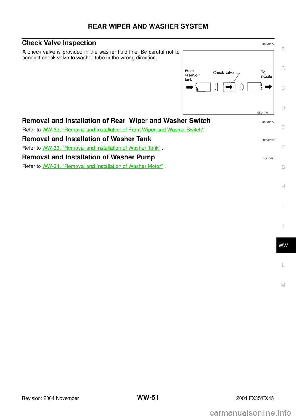
A check valve is provided in the washer fluid line. Be careful not to
connect check valve to washer tube in the wrong direction.
Removal and Installation of Rear Wiper and Washer SwitchAKS0057Y
Refer to WW-33, "Removal and Installation of Front Wiper and Washer Switch" .
Removal and Installation of Washer TankAKS0057Z
Refer to WW-33, "Removal and Installation of Washer Tank" .
Removal and Installation of Washer PumpAKS00580
Refer to WW-34, "Removal and Installation of Washer Motor" .
SEL411H