Belt diagram INFINITI FX35 2005 Service Manual
[x] Cancel search | Manufacturer: INFINITI, Model Year: 2005, Model line: FX35, Model: INFINITI FX35 2005Pages: 4731, PDF Size: 60.13 MB
Page 10 of 4731
ACS-1
AUTO CRUISE CONTROL SYSTEM
K ELECTRICAL
CONTENTS
C
D E
F
G H
I
J
L
M
SECTION ACS
A
B
ACS
Revision: 2005 July 2005 FX
AUTO CRUISE CONTROL SYSTEM
ASCD
AUTOMATIC SPEED CONTROL DEVICE (ASCD) ..... 3
Description .......................................................... ..... 3
ICC
PRECAUTIONS ..................................................... ..... 4
Precautions for Supplemental Restraint System
(SRS) “AIR BAG” and “SEAT BELT PRE-TEN-
SIONER” ............................................................. ..... 4
Precautions for ICC System Service ................... ..... 4
PREPARATION ...................................................... ..... 5
Special Service Tools .......................................... ..... 5
DESCRIPTION ....................................................... ..... 6
Outline ................................................................. ..... 6
VEHICLE-TO-VEHICLE DISTANCE CONTROL
MODE .............................................................. ..... 6
CONVENTIONAL (FIXED SPEED) CRUISE
CONTROL MODE ............................................ ..... 6
BRAKE ASSIST (WITH PREVIEW FUNCTION) ..... 6
System Diagram .................................................. ..... 6
Components Description ..................................... ..... 7
CAN Communication ........................................... ..... 7
CAN COMMUNICATION UNIT ........................ ..... 7
Switch Operation ................................................. ..... 8
ICC System Display ............................................ ..... 8
ACTION TEST ....................................................... ..... 9
ICC System Running Test ................................... ..... 9
VEHICLE-TO-VEHICLE DISTANCE CONTROL
MODE .............................................................. ..... 9
CONVENTIONAL (FIXED SPEED) CRUISE
CONTROL MODE ............................................ ... 10
LASER BEAM AIMING ADJUSTMENT ................ ... 12
Outline ................................................................. ... 12
Preparation .......................................................... ... 12
Outline of Adjustment Procedure ........................ ... 12
Setting the ICC Target Board .............................. ... 12
ADJUSTING HEIGHT OF THE TARGET ......... ... 12
ADJUSTING THE RIGHT-LEFT POSITION OF
THE TARGET ................................................... ... 13 SETTING THE TARGET ..................................
... 13
Aiming Adjustment ............................................... ... 14
CHECK AFTER THE ADJUSTMENT ............... ... 17
ELECTRICAL UNITS LOCATION ......................... ... 18
Component Parts and Harness Connector Location ... 18
WIRING DIAGRAM ................................................ ... 19
Schematic ............................................................ ... 19
Wiring Diagram — ICC — ................................... ... 20
TERMINALS AND REFERENCE VALUE .............. ... 27
Terminals and Reference Value for ICC Unit ....... ... 27
Terminals and Reference Value for ICC Sensor .. ... 28
TROUBLE DIAGNOSIS — GENERAL DESCRIP-
TION ....................................................................... ... 29
Work Flow ............................................................ ... 29
CONSULT-II Function .......................................... ... 30
DESCRIPTION ................................................. ... 30
CONSULT-II BASIC OPERATION .................... ... 30
WORK SUPPORT ............................................ ... 31
SELF-DIAGNOSTIC RESULTS ........................ ... 32
DATA MONITOR .............................................. ... 32
ACTIVE TEST .................................................. ... 34
Self-Diagnostic Function ...................................... ... 36
WITH CONSULT-II ........................................... ... 36
WITHOUT CONSULT-II .................................... ... 36
SELF-DIAGNOSIS BY ICC SYSTEM DISPLAY
WILL NOT RUN ................................................ ... 38
TROUBLE DIAGNOSIS FOR SELF-DIAGNOSTIC
ITEMS ..................................................................... ... 41
Diagnostic Trouble Code (DTC) Chart ................ ... 41
DTC 11 CONTROL UNIT .................................... ... 42
DTC 20 CAN COMM CIRCUIT ............................ ... 43
DTC 31 POWER SUPPLY CIR, DTC 34 POWER
SUPPLY CIR 2 .................................................... ... 43
DTC 41 VHCL SPEED SE CIRC ......................... ... 44
DTC 43 ABS/TCS/VDC CIRC ............................. ... 45
DTC 45 BRAKE SW/STOP L SW ........................ ... 45
DTC 46 OPERATION SW CIRC .......................... ... 47
DTC 61 PRESS SEN CIRCUIT ........................... ... 48
DTC 62 BOOSTER SOL/V CIRCUIT .................. ... 50
DTC 63 RELEASE SW CIRCUIT ........................ ... 51
Page 84 of 4731
AT-1
AUTOMATIC TRANSMISSION
C TRANSMISSION/TRANSAXLE
CONTENTS
D E
F
G H
I
J
K L
M
SECTION AT
A
B
AT
Revision: 2005 July 2005 FX
AUTOMATIC TRANSMISSION
INDEX FOR DTC ........................................................ 5
Alphabetical Index ............................................... ..... 5
DTC No. Index .................................................... ..... 6
PRECAUTIONS ..................................................... ..... 7
Precautions for Supplemental Restraint System
(SRS) “AIR BAG” and “SEAT BELT PRE-TEN-
SIONER” ............................................................. ..... 7
Precautions for On Board Diagnostic (OBD) System
of A/T and Engine ............................................... ..... 7
Precautions ......................................................... ..... 8
Service Notice or Precautions ............................. ..... 9
PREPARATION ...................................................... ... 10
Special Service Tools .......................................... ... 10
Commercial Service Tools ................................... .... 11
A/T FLUID .............................................................. ... 12
Changing A/T Fluid ............................................. ... 12
Checking A/T Fluid .............................................. ... 13
A/T Fluid Cooler Cleaning ................................... ... 15
A/T CONTROL SYSTEM ....................................... ... 18
Cross-Sectional View (2WD Models) .................. ... 18
Cross-Sectional View (AWD Models) .................. ... 19
Shift Mechanism .................................................. ... 20
TCM Function ...................................................... ... 31
CAN Communication ........................................... ... 32
Input/Output Signal of TCM ................................. ... 32
Line Pressure Control ......................................... ... 33
Shift Control ........................................................ ... 34
Lock-up Control ................................................... ... 35
Engine Brake Control .......................................... ... 36
Control Valve ....................................................... ... 37
ON BOARD DIAGNOSTIC (OBD) SYSTEM ......... ... 39
Introduction ......................................................... ... 39
OBD-II Function for A/T System .......................... ... 39
One or Two Trip Detection Logic of OBD-II ......... ... 39
OBD-II Diagnostic Trouble Code (DTC) .............. ... 39
Malfunction Indicator Lamp (MIL) ........................ ... 42
TROUBLE DIAGNOSIS ......................................... ... 43
DTC Inspection Priority Chart ............................. ... 43
Fail-safe .............................................................. ... 43
How to Perform Trouble Diagnosis for Quick and Accurate Repair ...................................................
... 45
A/T Electrical Parts Location ............................... ... 50
Circuit Diagram .................................................... ... 51
Inspections Before Trouble Diagnosis ................. ... 52
Check Before Engine Is Started .......................... ... 56
Check at Idle ........................................................ ... 57
Cruise Test - Part 1 .............................................. ... 58
Cruise Test - Part 2 .............................................. ... 60
Cruise Test - Part 3 .............................................. ... 61
Vehicle Speed at Which Gear Shifting Occurs .... ... 62
Vehicle Speed at Which Lock-up Occurs/Releases ... 63
Symptom Chart .................................................... ... 64
TCM Input/Output Signal Reference Values ........ ... 89
CONSULT-II Function (A/T) ................................. ... 90
Diagnostic Procedure without CONSULT-II ......... .103
DTC U1000 CAN COMMUNICATION LINE ........... .106
Description ........................................................... .106
On Board Diagnosis Logic ................................... .106
Possible Cause .................................................... .106
DTC Confirmation Procedure .............................. .106
Wiring Diagram — AT — CAN ............................. .107
Diagnostic Procedure .......................................... .108
DTC P0615 START SIGNAL CIRCUIT .................. .109
Description ........................................................... .109
CONSULT-II Reference Value ............................. .109
On Board Diagnosis Logic ................................... .109
Possible Cause .................................................... .109
DTC Confirmation Procedure .............................. .109
Wiring Diagram — AT — STSIG ......................... .110
Diagnostic Procedure .......................................... ..111
DTC P0700 TCM .................................................... .113
Description ........................................................... .113
On Board Diagnosis Logic ................................... .113
Possible Cause .................................................... .113
DTC Confirmation Procedure .............................. .113
Diagnostic Procedure .......................................... .113
DTC P0705 PARK/NEUTRAL POSITION SWITCH .114
Description ........................................................... .114
CONSULT-II Reference Value ............................. .114
On Board Diagnosis Logic ................................... .114
Page 600 of 4731
AV-1
AUDIO VISUAL, NAVIGATION & TELEPHONE SYS- TEM
K ELECTRICAL
CONTENTS
C
D E
F
G H
I
J
L
M
SECTION AV
A
B
AV
Revision: 2005 July 2005 FX
AUDIO VISUAL, NAVIGATION & TELEPHONE SYSTEM
PRECAUTIONS .......................................................... 5
Precautions for Supplemental Restraint System
(SRS) “AIR BAG” and “SEAT BELT PRE-TEN-
SIONER” ............................................................. ..... 5
PREPARATION ...................................................... ..... 6
Commercial Service Tools ................................... ..... 6
AUDIO .................................................................... ..... 7
Component Parts and Harness Connector Location ..... 7
System Description ............................................. ..... 8
BASE SYSTEM ................................................ ..... 8
BOSE SYSTEM ............................................... ..... 8
SPEED SENSITIVE VOLUME SYSTEM ......... ..... 9
Schematic - Base System - ................................. ... 10
Wiring Diagram - AUDIO - / Base System .......... .... 11
Schematic - BOSE System - With Navigation Sys-
tem ...................................................................... ... 16
Wiring Diagram – AUDIO – / BOSE System With
Navigation System .............................................. ... 17
Schematic - BOSE System - Without Navigation
System ................................................................ ... 25
Wiring Diagram – AUDIO – / BOSE System Without
Navigation System .............................................. ... 26
Terminals and Reference Value for Audio Unit .... ... 33
Terminals and Reference Value for BOSE Speaker
Amp. .................................................................... ... 34
Terminals and Reference Value for A/C and AV
Switch .................................................................. ... 36
Terminals and Reference Value for Woofer ......... ... 37
A/C and AV Switch Self-Diagnosis Function ....... ... 37
STARTING THE SELF-DIAGNOSIS MODE .... ... 37
EXITING THE SELF-DIAGNOSIS MODE ........ ... 37
DIAGNOSIS FUNCTION .................................. ... 37
Trouble Diagnosis ............................................... ... 38
MALFUNCTION WITH RADIO, TAPE AND CD ... 38
FOR RADIO ONLY ........................................... ... 39
FOR CASSETTE PLAYER ONLY .................... ... 39
FOR CD ONLY ................................................. ... 39
Noise Inspection .................................................. ... 40
TYPE OF NOISE AND POSSIBLE CAUSE ..... ... 40
Power Supply Circuit Inspection ......................... ... 41 Audio Steering Wheel Switch Inspection .............
... 42
A/C and AV Switch Inspection ............................. ... 44
BOSE Speaker Amp. Inspection ......................... ... 44
Vehicle Speed Signal Inspection ......................... ... 45
Locking CD Auto-Changer Mechanism ............... ... 46
DAMPER LOCK PROCEDURE ....................... ... 46
Removal and Installation of Audio Unit ................ ... 47
REMOVAL ........................................................ ... 47
INSTALLATION ................................................ ... 47
Disassembly and Assembly for Audio Unit .......... ... 47
DISASSEMBLY ................................................ ... 47
ASSEMBLY ...................................................... ... 47
Removal and Installation for A/C and AV Switch . ... 48
REMOVAL ........................................................ ... 48
INSTALLATION ................................................ ... 48
Removal and Installation for Front Door Speaker ... 48
REMOVAL ........................................................ ... 48
INSTALLATION ................................................ ... 48
Removal and Installation for Rear Door Speaker ... 49 REMOVAL ........................................................ ... 49
INSTALLATION ................................................ ... 49
Removal and Installation for Instrument Speaker ... 49 REMOVAL ........................................................ ... 49
INSTALLATION ................................................ ... 49
Removal and Installation for Tweeter .................. ... 49
REMOVAL ........................................................ ... 49
INSTALLATION ................................................ ... 49
Removal and Installation for Woofer (BOSE Sys-
tem) ..................................................................... ... 50
REMOVAL ........................................................ ... 50
INSTALLATION ................................................ ... 50
Removal and Installation for BOSE Speaker Amp. ... 50
REMOVAL ........................................................ ... 50
INSTALLATION ................................................ ... 50
AUDIO ANTENNA ................................................. ... 51
System Description .............................................. ... 51
Wiring Diagram — M/ANT — .............................. ... 52
Terminals and Reference Value for Audio Unit .... ... 53
Antenna Amp. Inspection .................................... ... 53
Location of Antenna ............................................. ... 54
Page 816 of 4731
BL-1
BODY, LOCK & SECURITY SYSTEM
I BODY
CONTENTS
C
D E
F
G H
J
K L
M
SECTION BL
A
B
BL
Revision: 2005 July 2005 FX
BODY, LOCK & SECURITY SYSTEM
PRECAUTIONS .......................................................... 5
Precautions for Supplemental Restraint System
(SRS) “AIR BAG” and “SEAT BELT PRE-TEN-
SIONER” ............................................................. ..... 5
Precautions Necessary for Steering Wheel Rotation
After Battery Disconnect ..................................... ..... 5
OPERATION PROCEDURE ............................ ..... 5
Precautions for Work ........................................... ..... 5
PREPARATION ...................................................... ..... 6
Special Service Tools .......................................... ..... 6
Commercial Service Tools ................................... ..... 6
SQUEAK AND RATTLE TROUBLE DIAGNOSIS . ..... 7
Work Flow ........................................................... ..... 7
CUSTOMER INTERVIEW ................................ ..... 7
DUPLICATE THE NOISE AND TEST DRIVE .. ..... 8
CHECK RELATED SERVICE BULLETINS ...... ..... 8
LOCATE THE NOISE AND IDENTIFY THE
ROOT CAUSE ................................................. ..... 8
REPAIR THE CAUSE ...................................... ..... 8
CONFIRM THE REPAIR .................................. ..... 9
Generic Squeak and Rattle Troubleshooting ...... ..... 9
INSTRUMENT PANEL ..................................... ..... 9
CENTER CONSOLE ........................................ ..... 9
DOORS ............................................................ ..... 9
TRUNK ............................................................. ... 10
SUNROOF/HEADLINING ................................ ... 10
SEATS .............................................................. ... 10
UNDERHOOD .................................................. ... 10
Diagnostic Worksheet ......................................... .... 11
HOOD .................................................................... ... 13
Fitting Adjustment ............................................... ... 13
LONGITUDINAL AND LATERAL CLEARANCE
ADJUSTMENT ................................................. ... 13
FRONT END HEIGHT ADJUSTMENT ............ ... 13
SURFACE HEIGHT ADJUSTMENT ................ ... 13
Removal and Installation of Hood Assembly ....... ... 14
REMOVAL ........................................................ ... 15
INSTALLATION ................................................ ... 15
Removal and Installation of Hood Lock Control .. ... 15
REMOVAL ........................................................ ... 15 INSTALLATION ................................................
... 16
Hood Lock Control Inspection ............................. ... 16
RADIATOR CORE SUPPORT ............................... ... 18
Removal and Installation ..................................... ... 18
REMOVAL ........................................................ ... 18
INSTALLATION ................................................ ... 19
FRONT FENDER ................................................... ... 20
Removal and Installation ..................................... ... 20
REMOVAL ........................................................ ... 20
INSTALLATION ................................................ ... 20
POWER DOOR LOCK SYSTEM ........................... ... 21
Component Parts and Harness Connector Location ... 21
Component Parts and Harness Connector Location ... 22
System Description .............................................. ... 22
OUTLINE .......................................................... ... 23
CAN Communication System Description ........... ... 24
CAN Communication Unit .................................... ... 24
Schematic/With Intelligent Key ............................ ... 25
Wiring Diagram -D/LOCK-/With Intelligent Key ... ... 26
FIG. 1 ................................................................ ... 26
FIG. 2 ................................................................ ... 27
FIG. 3 ................................................................ ... 28
FIG. 4 ................................................................ ... 29
FIG. 5 ................................................................ ... 30
Schematic/Without Intelligent Key ....................... ... 31
Wiring Diagram -D/LOCK-/Without Intelligent Key ... 32
FIG. 6 ................................................................ ... 32
FIG. 7 ................................................................ ... 33
FIG. 8 ................................................................ ... 34
FIG. 9 ................................................................ ... 35
Terminals and Reference Value for BCM ............ ... 36
Terminals and Reference Value for Intelligent Key
Unit (With Intelligent Key System) ....................... ... 36
Work Flow ............................................................ ... 36
CONSULT-II Function (BCM) .............................. ... 37
CONSULT-II INSPECTION PROCEDURE ....... ... 37
CONSULT-II APPLICATION ITEMS ................. ... 38
Trouble Diagnosis Chart by Symptom ................. ... 40
Check BCM Power Supply and Ground Circuit ... ... 41
Check Door Switch .............................................. ... 42
Page 1142 of 4731

BRC-1
BRAKE CONTROL SYSTEM
F BRAKES
CONTENTS
C
D E
G H
I
J
K L
M
SECTION BRC
A
B
BRC
Revision: 2005 July 2005 FX
BRAKE CONTROL SYSTEM
VDC/TCS/ABS
PRECAUTIONS .......................................................... 3
Precautions for Supplemental Restraint System
(SRS) “AIR BAG” and “SEAT BELT PRE-TEN-
SIONER” ............................................................. ..... 3
Precautions for Brake System ............................. ..... 3
Precautions for Brake Control ............................. ..... 3
PREPARATION ...................................................... ..... 5
Special Service Tools .......................................... ..... 5
Commercial Service Tools ................................... ..... 5
ON-VEHICLE SERVICE ........................................ ..... 6
Adjustment of Steering Angle Sensor Neutral Posi-
tion ...................................................................... ..... 6
Calibration of Decel G Sensor (AWD Model) ...... ..... 6
SYSTEM DESCRIPTION ....................................... ..... 8
System Diagram .................................................. ..... 8
VDC Function ...................................................... ..... 8
TCS Function ...................................................... ..... 8
ABS Function ...................................................... ..... 8
EBD Function ...................................................... ..... 9
Fail-Safe Function ............................................... ..... 9
VDC / TCS SYSTEM ........................................ ..... 9
ABS, EBD SYSTEM ......................................... ..... 9
Hydraulic Circuit Diagram ................................... ... 10
CAN COMMUNICATION ....................................... ....11
System Description ............................................. .... 11
TROUBLE DIAGNOSIS ......................................... ... 12
How to Proceed with Diagnosis .......................... ... 12
BASIC CONCEPT ............................................ ... 12
DIAGNOSIS FLOWCHART ............................. ... 13
ASKING COMPLAINTS ................................... ... 14
EXAMPLE OF DIAGNOSIS SHEET ................ ... 14
Component Installation Location ......................... ... 15
Schematic ........................................................... ... 16
Wiring Diagram — VDC — .................................. ... 17
Control Unit Input/Output Signal Standard .......... ... 23
REFERENCE VALUE FROM CONSULT-II ...... ... 23
CONSULT-II Functions ........................................ ... 25
CONSULT-II MAIN FUNCTION ........................ ... 25
CONSULT-II BASIC OPERATION PROCEDURE ... 26
SELF-DIAGNOSIS ........................................... ... 27
DATA MONITOR .............................................. ... 30
ACTIVE TEST .................................................. ... 33
For Fast and Accurate Diagnosis ........................ ... 35
PRECAUTIONS FOR DIAGNOSIS .................. ... 35
Basic Inspection .................................................. ... 36
BASIC INSPECTION 1: BRAKE FLUID
AMOUNT, LEAKS, AND BRAKE PADS INSPEC-
TION ................................................................. ... 36
BASIC INSPECTION 2: POWER SYSTEM TER-
MINAL LOOSENESS AND BATTERY INSPEC-
TION ................................................................. ... 36
BASIC INSPECTION 3: ABS WARNING LAMP,
VDC OFF INDICATOR LAMP, SLIP INDICATOR
LAMP AND BRAKE WARNING LAMP INSPEC-
TION ................................................................. ... 37
Inspection 1: Wheel Sensor Circuit ..................... ... 37
Inspection 2: Engine System ............................... ... 39
Inspection 3: VDC/TCS/ABS Control Unit Circuit ... 40
Inspection 4: Pressure Sensor Circuit ................. ... 40
Inspection 5: Steering Angle Sensor Circuit ........ ... 42
Inspection 6: Yaw Rate/Side G Sensor (2WD
Model), Yaw Rate/Side/Decel G sensor (AWD Mod-
els) Circuit ............................................................ ... 44
Inspection 7: Solenoid and VDC Change-Over
Valve Circuit ......................................................... ... 46
Inspection 8: Actuator Motor Circuit .................... ... 47
Inspection 9: ABS Actuator and Electric Unit (Con-
trol Unit) Power Supply and Ground Circuit ......... ... 48
Inspection 10: Stop Lamp Switch Circuit ............. ... 50
Inspection 11: Brake Fluid Level Switch Circuit ... ... 51
Inspection 12: When “ST ANG SEN SIGNAL”
Appears on Self-diagnosis Results Display ......... ... 52
Inspection 13: When “DECEL G SEN SET” Appears
on Self-diagnostic Results Display (AWD Model) ... 52
Inspection 14: CAN Communication Circuit ........ ... 53
Component Inspection ......................................... ... 53
VDC OFF SWITCH .......................................... ... 53
Symptom 1: Excessive ABS Function Operation
Page 1262 of 4731

DI-1
DRIVER INFORMATION SYSTEM
K ELECTRICAL
CONTENTS
C
D E
F
G H
I
J
L
M
SECTION DI
A
B
DI
Revision: 2005 July 2005 FX
DRIVER INFORMATION SYSTEM
PRECAUTION ............................................................ 4
Precautions for Supplemental Restraint System
(SRS) “AIR BAG” and “SEAT BELT PRE-TEN-
SIONER” ............................................................. ..... 4
COMBINATION METERS ...................................... ..... 5
System Description ............................................. ..... 5
UNIFIED METER CONTROL UNIT ................. ..... 5
UNIFIED METER AND A/C AMP. .................... ..... 5
HOW TO CHANGE THE DISPLAY FOR ODO/
TRIP METER ................................................... ..... 6
POWER SUPPLY AND GROUND CIRCUIT ... ..... 6
SPEEDOMETER .............................................. ..... 7
TACHOMETER ................................................ ..... 7
WATER TEMPERATURE GAUGE ................... ..... 7
FUEL GAUGE .................................................. ..... 7
Component Parts and Harness Connector Location ..... 7
Arrangement of Combination Meter .................... ..... 8
Circuit Diagram ................................................... ..... 9
Wiring Diagram — METER — ............................. ... 10
Terminals and Reference Value for Combination
Meter ................................................................... ... 12
Terminals and Reference Value for Unified Meter
and A/C Amp. ...................................................... ... 13
Self-Diagnosis Mode of Combination Meter ........ ... 14
SELF-DIAGNOSIS FUNCTION ....................... ... 14
OPERATION PROCEDURE ............................ ... 14
CONSULT-II Function (METER A/C AMP) .......... ... 14
Trouble Diagnosis ............................................... ... 15
HOW TO PERFORM TROUBLE DIAGNOSIS ... 15
PRELIMINARY CHECK ................................... ... 15
Symptom Chart 1 ................................................ ... 17
Symptom Chart 2 ................................................ ... 17
Power Supply and Ground Circuit Inspection ..... ... 18
Vehicle Speed Signal Inspection ......................... ... 20
Engine Speed Signal Inspection ......................... ... 21
Engine Coolant Temperature Signal Inspection .. ... 21
Fuel Level Sensor Signal Inspection ................... ... 22
Odo/Trip Meter and Illumination Control Switch
Inspection ............................................................ ... 24
Fuel Gauge Pointer Fluctuates, Indicator Wrong Value or Varies ....................................................
... 24
Fuel Gauge Does Not Move to FULL Position .... ... 24
Electrical Components Inspection ....................... ... 25
CHECK FUEL LEVEL SENSOR UNIT ............. ... 25
Removal and Installation of Combination Meter .. ... 25
Disassembly and Assembly of Combination Meter ... 26
DISASSEMBLY ................................................ ... 26
ASSEMBLY ...................................................... ... 27
Removal and Installation of Odo/Trip Meter and Illu-
mination Control Switch ....................................... ... 27
REMOVAL ........................................................ ... 27
INSTALLATION ................................................ ... 27
UNIFIED METER AND A/C AMP ........................... ... 28
System Description .............................................. ... 28
INPUT/OUTPUT SIGNALS .............................. ... 28
FAIL-SAFE ....................................................... ... 29
CAN Communication System Description ........... ... 29
CAN Communication Unit .................................... ... 29
Schematic ............................................................ ... 30
CONSULT-II Function (METER A/C AMP) .......... ... 31
CONSULT-II BASIC OPERATION .................... ... 31
SELF-DIAGNOSTIC RESULTS ........................ ... 32
DATA MONITOR .............................................. ... 32
DTC [U1000] CAN Communication Circuit .......... ... 34
DTC [B2202] Meter Communication Circuit ........ ... 34
DTC [B2205] Vehicle Speed Circuit ..................... ... 37
Removal and Installation of Unified Meter and A/C
Amp. .................................................................... ... 37
REMOVAL ........................................................ ... 37
INSTALLATION ................................................ ... 37
COMPASS .............................................................. ... 38
System Description .............................................. ... 38
DIRECTION DISPLAY ...................................... ... 38
Wiring Diagram – COMPAS – ............................. ... 40
Removal and Installation of Compass ................. ... 41
WARNING LAMPS ................................................. ... 42
Schematic ............................................................ ... 42
Wiring Diagram — WARN — ............................... ... 43
Oil Pressure Warning Lamp Stays Off (Ignition
Switch ON) .......................................................... ... 51
Page 1263 of 4731

DI-2Revision: 2005 July 2005 FX
Oil Pressure Warning Lamp Does Not Turn Off (Oil
Pressure Is Normal) ............................................. ... 52
Component Inspection ......................................... ... 53
OIL PRESSURE SWITCH ................................ ... 53
A/T INDICATOR ..................................................... ... 54
Wiring Diagram — AT/IND — .............................. ... 54
A/T Indicator Is Malfunction ................................. ... 56
WARNING CHIME .................................................. ... 58
System Description .............................................. ... 58
FUNCTION ....................................................... ... 58
IGNITION KEY WARNING CHIME (WITHOUT
INTELLIGENT KEY) ......................................... ... 58
IGNITION KEY WARNING CHIME (WITH INTEL-
LIGENT KEY) ................................................... ... 59
LIGHT WARNING CHIME ................................ ... 59
SEAT BELT WARNING CHIME ........................ ... 59
CAN Communication System Description ........... ... 60
CAN Communication Unit .................................... ... 60
Component Parts and Harness Connector Location ... 61
Schematic ............................................................ ... 62
Wiring Diagram — CHIME — .............................. ... 63
Terminals and Reference Value for BCM ............. ... 66
Terminals and Reference Value for Unified Meter
and A/C Amp. ...................................................... ... 67
Terminals and Reference Value for Combination
Meter ................................................................... ... 67
Trouble Diagnosis ................................................ ... 68
HOW TO PERFORM TROUBLE DIAGNOSIS . ... 68
PRELIMINARY CHECK .................................... ... 68
CONSULT-II Function (BCM) ............................... ... 69
DIAGNOSTIC ITEMS DESCRIPTION .............. ... 69
CONSULT-II BASIC OPERATION PROCEDURE
... 69
DATA MONITOR ............................................... ... 70
ACTIVE TEST .................................................. ... 70
SELF-DIAGNOSTIC RESULTS ........................ ... 71
All Warnings Are Not Operated ........................... ... 71
Key Warning Chime and Light Warning Chime Does
Not Operate (Seat Belt Warning Chime Does Oper-
ate) ...................................................................... ... 72
Key Warning Chime Does Not Operate (Without
Intelligent Key) ..................................................... ... 73
Key Warning Chime Does Not Operate (With Intel-
ligent Key, When Mechanical Key Is Used) ......... ... 75
Key Warning Chime Does Not Operate (With Intel-
ligent Key, When Intelligent Key Is Carried With The
Driver) .................................................................. ... 77
Light Warning Chime Does Not Operate ............. ... 79
Seat Belt Warning Chime Does Not Operate ...... ... 80
LANE DEPARTURE WARNING SYSTEM ............. ... 82
Precautions for Lane Departure Warning (LDW)
system ................................................................. ... 82
System Description .............................................. ... 82
LDW SYSTEM OPERATION ............................ ... 82
POWER SUPPLY AND GROUND CIRCUIT .... ... 84
CAN Communication ........................................... ... 84
SYSTEM DESCRIPTION ................................. ... 84
CAN COMMUNICATION UNIT ......................... ... 85
Action Test ........................................................... ... 85 LDW SYSTEM RUNNING TEST ......................
... 85
Camera Aiming Adjustment ................................. ... 86
OUTLINE .......................................................... ... 86
PREPARATION ................................................. ... 86
TARGET SETTING ........................................... ... 86
VEHICLE HEIGHT CHECK .............................. ... 89
AIMING ADJUSTMENT .................................... ... 89
Component Parts and Harness Connector Location ... 93
Schematic ............................................................ ... 94
Wiring Diagram — LDW — .................................. ... 95
Terminals and Reference Value for LDW Camera
Unit ....................................................................... ... 98
CONSULT-II Function (LDW) ............................... ... 98
DESCRIPTION ................................................. ... 98
CONSULT-II BASIC OPERATION .................... ... 98
WORK SUPPORT ............................................ ... 99
SELF-DIAG RESULTS ...................................... ... 99
DATA MONITOR ............................................... .100
ACTIVE TEST ................................................... .101
Trouble Diagnosis ................................................ .102
HOW TO PERFORM TROUBLE DIAGNOSIS . .102
SYMPTOM CHART ........................................... .102
Preliminary Inspection .......................................... .103
Power Supply and Ground Circuit Inspection ...... .104
DTC [C1B00] CAMERA UNIT MALF ................... .104
DTC [C1B01] CAM AIMING INCMP .................... .104
DTC [C1B02] VHCL SPD DATA MALF ................ .105
DTC [C1B03] ABNRML TEMP DETECT ............. .105
DTC [U1000] CAN COMM CIRCUIT ................... .105
DTC [U1010] CONTROL UNIT (CAN) ................. .105
LDW Chime Circuit Inspection ............................. .106
LDW Switch Circuit Inspection ............................. .107
LDW Indicator Lamp Circuit Inspection ................ .109
Turn Signal Input Inspection ................................ .110
Removal and Installation for LDW Camera Unit .. . 111
REMOVAL ......................................................... . 111
INSTALLATION ................................................. . 111
Removal and Installation for LDW Chime ............ . 111
REMOVAL ......................................................... . 111
INSTALLATION ................................................. . 111
Removal and Installation for LDW Switch ............ . 111
CLOCK ................................................................... .112
Wiring Diagram — CLOCK — .............................. .112
Removal and Installation of Clock ........................ .113
REMOVAL ......................................................... .113
INSTALLATION ................................................. .113
REAR VIEW MONITOR .......................................... .114
System Description .............................................. .114
POWER SUPPLY AND GROUND .................... .114
AV COMMUNICATION LINE ............................ .114
REAR VIEW CAMERA OPERATION ............... .114
Component Parts and Harness Connector Location .115
Schematic ............................................................ .116
Wiring Diagram — R/VIEW — ............................. .117
Terminals and Reference Value for Rear View Cam-
era Control Unit .................................................... .120
CONSULT-II Function (REARVIEW CAMERA) ... .121
CONSULT-II BASIC OPERATION .................... .121
WORK SUPPORT ............................................ .122
Page 1336 of 4731
WARNING CHIME DI-75
C
D E
F
G H
I
J
L
M A
B
DI
Revision: 2005 July 2005 FX
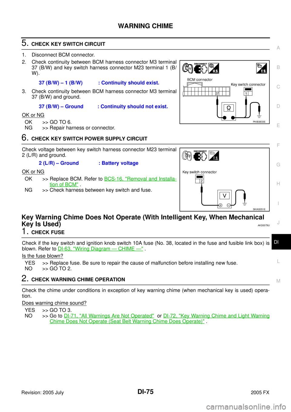
5. CHECK KEY SWITCH CIRCUIT
1. Disconnect BCM connector.
2. Check continuity between BCM harness connector M3 terminal 37 (B/W) and key switch harness connector M23 terminal 1 (B/
W).
3. Check continuity between BCM harness connector M3 terminal 37 (B/W) and ground.
OK or NG
OK >> GO TO 6.
NG >> Repair harness or connector.
6. CHECK KEY SWITCH POWER SUPPLY CIRCUIT
Check voltage between key switch harness connector M23 terminal
2 (L/R) and ground.
OK or NG
OK >> Replace BCM. Refer to BCS-16, "Removal and Installa-
tion of BCM" .
NG >> Check harness between key switch and fuse.
Key Warning Chime Does Not Operate (With Intelligent Key, When Mechanical
Key Is Used)
AKS0079U
1. CHECK FUSE
Check if the key switch and ignition knob switch 10A fuse (No. 38, located in the fuse and fusible link box) is
blown. Refer to DI-63, "
Wiring Diagram — CHIME —" .
Is the fuse blown?
YES >> Replace fuse. Be sure to repair the cause of malfunction before installing new fuse.
NO >> GO TO 2.
2. CHECK WARNING CHIME OPERATION
Check the chime under conditions in exception of key warning chime (when mechanical key is used) opera-
tion.
Does warning chime sound?
YES >> GO TO 3.
NO >> Go to DI-71, "
All Warnings Are Not Operated" or DI-72, "Key Warning Chime and Light Warning
Chime Does Not Operate (Seat Belt Warning Chime Does Operate)" .
37 (B/W) – 1 (B/W) : Continuity should exist.
37 (B/W) – Ground : Continuity should not exist.
PKIB3833E
2 (L/R) – Ground : Battery voltage
SKIA5051E
Page 1394 of 4731
EC-1
ENGINE CONTROL SYSTEM
B ENGINE
CONTENTS
C
D E
F
G H
I
J
K L
M
SECTION EC
A
EC
Revision: 2005 July 2005 FX
ENGINE CONTROL SYSTEM
VQ35DE
INDEX FOR DTC ...................................................... 15
DTC No. Index .................................................... ... 15
Alphabetical Index ............................................... ... 19
PRECAUTIONS ..................................................... ... 23
Precautions for Supplemental Restraint System
(SRS) “AIR BAG” and “SEAT BELT PRE-TEN-
SIONER” ............................................................. ... 23
On Board Diagnostic (OBD) System of Engine and
A/T ....................................................................... ... 23
Precaution ........................................................... ... 23
PREPARATION ...................................................... ... 27
Special Service Tools .......................................... ... 27
Commercial Service Tools ................................... ... 29
ENGINE CONTROL SYSTEM ............................... ... 30
System Diagram .................................................. ... 30
Multiport Fuel Injection (MFI) System ................. ... 31
Electronic Ignition (EI) System ............................ ... 33
Fuel Cut Control (at No Load and High Engine
Speed) ................................................................. ... 34
AIR CONDITIONING CUT CONTROL .................. ... 35
Input/Output Signal Chart .................................... ... 35
System Description ............................................. ... 35
AUTOMATIC SPEED CONTROL DEVICE (ASCD) ... 36
System Description ............................................. ... 36
Component Description ....................................... ... 37
CAN COMMUNICATION ....................................... ... 38
System Description ............................................. ... 38
EVAPORATIVE EMISSION SYSTEM .................... ... 39
Description .......................................................... ... 39
Component Inspection ........................................ ... 42
Removal and Installation ..................................... ... 43
How to Detect Fuel Vapor Leakage .................... ... 43
ON BOARD REFUELING VAPOR RECOVERY
(ORVR) ................................................................... ... 46
System Description ............................................. ... 46
Diagnostic Procedure .......................................... ... 47
Component Inspection ........................................ ... 49 POSITIVE CRANKCASE VENTILATION ..............
... 51
Description ........................................................... ... 51
Component Inspection ......................................... ... 51
IVIS (INFINITI VEHICLE IMMOBILIZER SYSTEM-
NATS) ..................................................................... ... 53
Description ........................................................... ... 53
ON BOARD DIAGNOSTIC (OBD) SYSTEM ......... ... 54
Introduction .......................................................... ... 54
Two Trip Detection Logic ..................................... ... 54
Emission-Related Diagnostic Information ............ ... 55
Malfunction Indicator Lamp (MIL) ........................ ... 69
OBD System Operation Chart ............................. ... 72
BASIC SERVICE PROCEDURE ............................ ... 78
Basic Inspection .................................................. ... 78
Idle Speed and Ignition Timing Check ................. ... 83
Idle Mixture Ratio Adjustment .............................. ... 85
VIN Registration .................................................. ... 96
Accelerator Pedal Released Position Learning ... ... 96
Throttle Valve Closed Position Learning .............. ... 96
Idle Air Volume Learning ..................................... ... 97
Fuel Pressure Check ........................................... ... 99
TROUBLE DIAGNOSIS ......................................... .101
Trouble Diagnosis Introduction ............................ .101
DTC Inspection Priority Chart .............................. .107
Fail-Safe Chart .................................................... .109
Symptom Matrix Chart ......................................... .110
Engine Control Component Parts Location ......... .114
Vacuum Hose Drawing ........................................ .120
Circuit Diagram .................................................... .121
ECM Harness Connector Terminal Layout .......... .123
ECM Terminals and Reference Value .................. .123
CONSULT-II Function (ENGINE) ......................... .132
Generic Scan Tool (GST) Function ...................... .144
CONSULT-II Reference Value in Data Monitor .... .147
Major Sensor Reference Graph in Data Monitor
Mode .................................................................... .151
TROUBLE DIAGNOSIS - SPECIFICATION VALUE .153
Description ........................................................... .153
Testing Condition ................................................. .153
Page 1401 of 4731

EC-8Revision: 2005 July 2005 FX
VK45DE
INDEX FOR DTC .....................................................707
DTC No. Index ..................................................... .707
Alphabetical Index ............................................... .711
PRECAUTIONS ...................................................... .715
Precautions for Supplemental Restraint System
(SRS) “AIR BAG” and “SEAT BELT PRE-TEN-
SIONER” .............................................................. .715
On Board Diagnostic (OBD) System of Engine and
A/T ....................................................................... .715
Precaution ........................................................... .715
PREPARATION ...................................................... .719
Special Service Tools .......................................... .719
Commercial Service Tools ................................... .720
ENGINE CONTROL SYSTEM ............................... .721
System Diagram .................................................. .721
Multiport Fuel Injection (MFI) System .................. .722
Electronic Ignition (EI) System ............................ .724
Fuel Cut Control (at No Load and High Engine
Speed) ................................................................. .725
AIR CONDITIONING CUT CONTROL ................... .726
Input/Output Signal Chart .................................... .726
System Description .............................................. .726
AUTOMATIC SPEED CONTROL DEVICE (ASCD) .727
System Description .............................................. .727
Component Description ....................................... .728
CAN COMMUNICATION ........................................ .729
System Description .............................................. .729
EVAPORATIVE EMISSION SYSTEM .................... .730
Description ........................................................... .730
Component Inspection ......................................... .733
Removal and Installation ..................................... .734
How to Detect Fuel Vapor Leakage ..................... .734
ON BOARD REFUELING VAPOR RECOVERY
(ORVR) ................................................................... .737
System Description .............................................. .737
Diagnostic Procedure .......................................... .738
Component Inspection ......................................... .740
POSITIVE CRANKCASE VENTILATION .............. .742
Description ........................................................... .742
Component Inspection ......................................... .742
IVIS (INFINITI VEHICLE IMMOBILIZER SYSTEM-
NATS) ..................................................................... .744
Description ........................................................... .744
ON BOARD DIAGNOSTIC (OBD) SYSTEM ......... .745
Introduction .......................................................... .745
Two Trip Detection Logic ..................................... .745
Emission-Related Diagnostic Information ............ .746
Malfunction Indicator Lamp (MIL) ........................ .760
OBD System Operation Chart ............................. .764
BASIC SERVICE PROCEDURE ............................ .769
Basic Inspection .................................................. .769
Idle Speed and Ignition Timing Check ................. .774
Idle Mixture Ratio Adjustment .............................. .775
VIN Registration .................................................. .786
Accelerator Pedal Released Position Learning ... .786
Throttle Valve Closed Position Learning .............. .786 Idle Air Volume Learning ......................................
.787
Fuel Pressure Check ........................................... .789
TROUBLE DIAGNOSIS ......................................... .791
Trouble Diagnosis Introduction ............................ .791
DTC Inspection Priority Chart .............................. .797
Fail-Safe Chart ..................................................... .799
Symptom Matrix Chart ......................................... .800
Engine Control Component Parts Location .......... .804
Vacuum Hose Drawing ........................................ .810
Circuit Diagram .................................................... .811
ECM Harness Connector Terminal Layout ........... .813
ECM Terminals and Reference Value .................. .813
CONSULT-II Function (ENGINE) ......................... .822
Generic Scan Tool (GST) Function ...................... .835
CONSULT-II Reference Value in Data Monitor .... .838
Major Sensor Reference Graph in Data Monitor
Mode .................................................................... .842
TROUBLE DIAGNOSIS - SPECIFICATION VALUE .844
Description ........................................................... .844
Testing Condition ................................................. .844
Inspection Procedure ........................................... .844
Diagnostic Procedure ........................................... .845
TROUBLE DIAGNOSIS FOR INTERMITTENT INCI-
DENT ...................................................................... .854
Description ........................................................... .854
Diagnostic Procedure ........................................... .854
POWER SUPPLY AND GROUND CIRCUIT .......... .855
Wiring Diagram .................................................... .855
Diagnostic Procedure ........................................... .856
Ground Inspection ................................................ .861
DTC U1000, U1001 CAN COMMUNICATION LINE .862
Description ........................................................... .862
On Board Diagnosis Logic ................................... .862
DTC Confirmation Procedure ............................... .862
Wiring Diagram .................................................... .863
Diagnostic Procedure ........................................... .864
DTC P0011, P0021 IVT CONTROL ........................ .865
Description ........................................................... .865
CONSULT-II Reference Value in Data Monitor Mode .866
On Board Diagnosis Logic ................................... .866
DTC Confirmation Procedure ............................... .867
Wiring Diagram .................................................... .868
Diagnostic Procedure ........................................... .871
Component Inspection ......................................... .875
Removal and Installation ...................................... .876
DTC P0031, P0032, P0051, P0052 HO2S1 HEATER .877
Description ........................................................... .877
CONSULT-II Reference Value in Data Monitor Mode .877
On Board Diagnosis Logic ................................... .877
DTC Confirmation Procedure ............................... .878
Wiring Diagram .................................................... .879
Diagnostic Procedure ........................................... .882
Component Inspection ......................................... .884
Removal and Installation ...................................... .884
DTC P0037, P0038, P0057, P0058 HO2S2 HEATER .885
Description ........................................................... .885
CONSULT-II Reference Value in Data Monitor Mode