ground INFINITI FX35 2006 Service Manual
[x] Cancel search | Manufacturer: INFINITI, Model Year: 2006, Model line: FX35, Model: INFINITI FX35 2006Pages: 4462, PDF Size: 57.74 MB
Page 1 of 4462
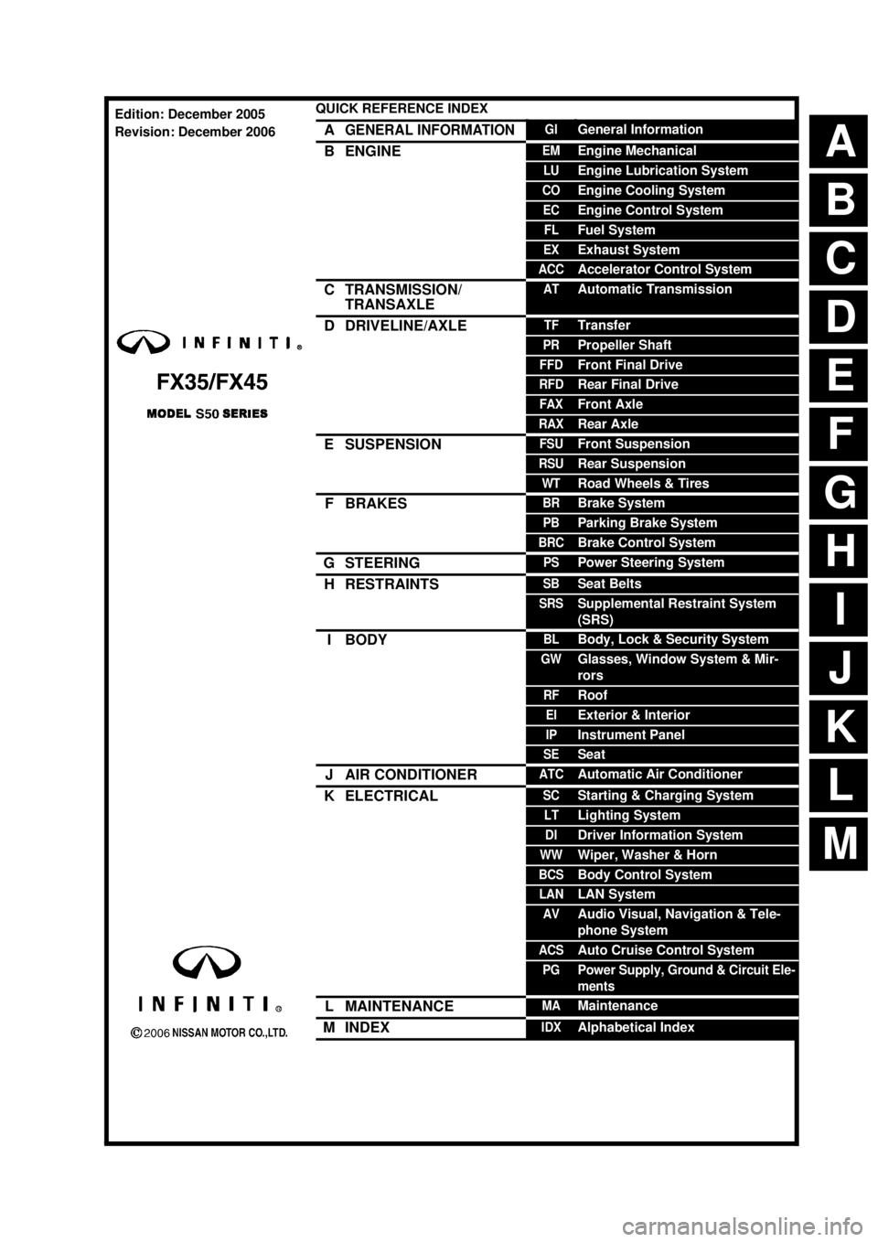
ABCDEFGHIJKMLQUICK REFERENCE INDEX AGENERAL INFORMATIONGIGeneral InformationBENGINEEMEngine MechanicalLUEngine Lubrication SystemCOEngine Cooling SystemECEngine Control SystemFLFuel SystemEXExhaust SystemACCAccelerator Control SystemCTRANSMISSION/
TRANSAXLEATAutomatic TransmissionDDRIVELINE/AXLETFTransferPRPropeller ShaftFFDFront Final DriveRFDRear Final DriveFAXFront AxleRAXRear AxleESUSPENSIONFSUFront SuspensionRSURear SuspensionWTRoad Wheels & TiresFBRAKESBRBrake SystemPBParking Brake SystemBRCBrake Control SystemGSTEERINGPSPower Steering SystemHRESTRAINTSSBSeat BeltsSRSSupplemental Restraint System
(SRS)IBODYBLBody, Lock & Security SystemGWGlasses, Window System & Mir-
rorsRFRoofEIExterior & InteriorIPInstrument PanelSESeatJAIR CONDITIONERATCAutomatic Air ConditionerKELECTRICALSCStarting & Charging SystemLTLighting SystemDIDriver Information SystemWWWiper, Washer & HornBCSBody Control SystemLANLAN SystemAVAudio Visual, Navigation & Tele-
phone SystemACSAuto Cruise Control SystemPGPower Supply, Ground & Circuit Ele-
mentsLMAINTENANCEMAMaintenanceMINDEXIDXAlphabetical IndexEdition: December 2005
Revision: December 2006
Page 23 of 4462
![INFINITI FX35 2006 Service Manual LASER BEAM AIMING ADJUSTMENT ACS-15
[ICC]
C
D E
F
G H
I
J
L
M A
B
ACS
Revision: 2006 December 2006 FX35/FX45
2. Adjust the height of the target board stand so that the point of the triang](/img/42/57019/w960_57019-22.png "INFINITI FX35 2006 Service Manual LASER BEAM AIMING ADJUSTMENT ACS-15
[ICC]
C
D E
F
G H
I
J
L
M A
B
ACS
Revision: 2006 December 2006 FX35/FX45
2. Adjust the height of the target board stand so that the point of the triang")
LASER BEAM AIMING ADJUSTMENT ACS-15
[ICC]
C
D E
F
G H
I
J
L
M A
B
ACS
Revision: 2006 December 2006 FX35/FX45
2. Adjust the height of the target board stand so that the point of the triangle aims the center of the ICC sensor.
ADJUSTING THE RIGHT-LEFT POSITION OF THE TARGET
1. Attach a scale [at least 350 mm (14 in) or longer] or stick asshown in the figure.
2. Suspend a thread with weight on the tip of the thread to 310 mm (12.2 in) left side of the target board from the center of the tar-
get board on top.
SETTING THE TARGET
1. Suspend a thread with weight on tip to splice the center of the front and rear bumpers. Then, mark the
center point on the ground as each weight points.
2. Link the front and rear bumpers center points marked on the ground, and mark a point 5 m (16.4 ft) ahead of the sensor, on the extended line of the previous link line of the bumper center points. Then, adjust the
position of the target board so that the weight come on the top of the marked point [5 m (16.4 ft) ahead of
the sensor] and face to the vehicle.
3. Adjust the position of the target board so that the extended line that links the center of the rear window glass (the center of the
rear window defogger pattern) and the center of the windshield
(the setting part of the room mirror) align with the weight sus-
pended from the board.
4. Remove the thread suspended to the left side of board and sus- pend a thread with weight on tip on the center of the target
board. Then mark the point of weight on the ground.
SKIA6180E
SKIA1211E
SKIA5975E
SKIA1213E
Page 36 of 4462
![INFINITI FX35 2006 Service Manual ACS-28
[ICC]
TERMINALS AND REFERENCE VALUE
Revision: 2006 December 2006 FX35/FX45
TERMINALS AND REFERENCE VALUEPFP:00000
Terminals and Reference Value for ICC UnitNKS003EY
Terminals
(Wire color) Ite](/img/42/57019/w960_57019-35.png "INFINITI FX35 2006 Service Manual ACS-28
[ICC]
TERMINALS AND REFERENCE VALUE
Revision: 2006 December 2006 FX35/FX45
TERMINALS AND REFERENCE VALUEPFP:00000
Terminals and Reference Value for ICC UnitNKS003EY
Terminals
(Wire color) Ite")
ACS-28
[ICC]
TERMINALS AND REFERENCE VALUE
Revision: 2006 December 2006 FX35/FX45
TERMINALS AND REFERENCE VALUEPFP:00000
Terminals and Reference Value for ICC UnitNKS003EY
Terminals
(Wire color) Item Condition
Voltage (V)
+– Ignition
switch Operation
1 (R/W)
2 (R/W)
Ground Battery power supply OFF — Battery voltage
5 (P) CAN-L — — —
6 (GY/L) Release switch power supply ON — Approx. 10
7 (GY/R) NEUT-SW ON Selector lever in “N” or “P” posi-
tions Approx. 12
Selector lever in other positions Approx. 0
8 (G) 24 (R) Brake pressure sensor power
supply ON — Approx. 5
10 (B/R)
Ground Brake booster solenoid
(+) side ON — Approx. 12
12 (L/W) Brake booster solenoid
(–) side ON Solenoid operating
Solenoid not operating Approx. 12
14 (L) CAN-H — — —
15 (LG/B) Brake release switch
(normal closed) ON Depress the brake pedal Approx. 0
Release the brake pedal Approx. 10
17 (BR) 24 (R) Brake pressure sensor signal ON Release the brake pedal Approx. 0.5
Depress the brake pedal Approx. 0.5 - 3
(Note) Voltage becomes higher depending on effectiveness of
depressing brakes.
19 (B)
20 (B)
46 (B)
Ground Ground ON — Approx. 0
22 (G/Y) Brake release switch
(normally open) ON Depress the brake pedal Approx. 10
Release the brake pedal Approx. 0
29 (SB) ICC brake switch
(normal closed) ON Selector
lever: Not
in “N” or
“P” posi-
tion Depress the brake
pedal Approx. 0
Release the brake
pedal Approx. 12
30 (Y) DDL-TX — — —
33 (W)
42 (W) Ignition switch ON or START ON — Battery voltage
38 (P/B) Stop lamp switch
(normally open) ON Depress the brake pedal Approx. 12
Release the brake pedal Approx. 0
39
(G/OR) DDL-RX — — —
PKIA9673E
Page 37 of 4462
![INFINITI FX35 2006 Service Manual TERMINALS AND REFERENCE VALUE ACS-29
[ICC]
C
D E
F
G H
I
J
L
M A
B
ACS
Revision: 2006 December 2006 FX35/FX45
Terminals and Reference Value for ICC SensorNKS003EZ
40
(PU/W)
Ground Parki](/img/42/57019/w960_57019-36.png "INFINITI FX35 2006 Service Manual TERMINALS AND REFERENCE VALUE ACS-29
[ICC]
C
D E
F
G H
I
J
L
M A
B
ACS
Revision: 2006 December 2006 FX35/FX45
Terminals and Reference Value for ICC SensorNKS003EZ
40
(PU/W)
Ground Parki")
TERMINALS AND REFERENCE VALUE ACS-29
[ICC]
C
D E
F
G H
I
J
L
M A
B
ACS
Revision: 2006 December 2006 FX35/FX45
Terminals and Reference Value for ICC SensorNKS003EZ
40
(PU/W)
Ground Parking brake signal ON
Depress the parking brake Approx. 0
Release the parking brake Approx. 12
47 (W/R) Stop lamp drive output signal ON Brake operating with ICC sys-
tem Approx. 12
Brake not operating with ICC
system Approx. 0
Terminals
(Wire color) Item Condition
Voltage (V)
+– Ignition
switch Operation
Terminals
(Wire color) Item Condition
Voltage (V)
+– Ignition
switch Operation
1 (Y)
Ground ICC sensor power ON — Battery voltage
3 (L) CAN-H — — —
4 (B) Ground — — Approx. 0
6 (R) CAN-L — — —
Page 47 of 4462
![INFINITI FX35 2006 Service Manual TROUBLE DIAGNOSIS — GENERAL DESCRIPTION ACS-39
[ICC]
C
D E
F
G H
I
J
L
M A
B
ACS
Revision: 2006 December 2006 FX35/FX45
SELF-DIAGNOSIS BY ICC SYSTEM DISPLAY WILL NOT RUN
Possible Irregu](/img/42/57019/w960_57019-46.png "INFINITI FX35 2006 Service Manual TROUBLE DIAGNOSIS — GENERAL DESCRIPTION ACS-39
[ICC]
C
D E
F
G H
I
J
L
M A
B
ACS
Revision: 2006 December 2006 FX35/FX45
SELF-DIAGNOSIS BY ICC SYSTEM DISPLAY WILL NOT RUN
Possible Irregu")
TROUBLE DIAGNOSIS — GENERAL DESCRIPTION ACS-39
[ICC]
C
D E
F
G H
I
J
L
M A
B
ACS
Revision: 2006 December 2006 FX35/FX45
SELF-DIAGNOSIS BY ICC SYSTEM DISPLAY WILL NOT RUN
Possible Irregular Condition
1. CHECK FUSES
Check that any of the fuses is blown.
OK or NG
OK >> GO TO 2.
NG >> If fuse is blown, be sure to eliminate cause of malfunction before installing new fuse.
2. CHECK ICC SYSTEM DISPLAY
1. Turn ignition switch ON.
2. Check if all displays illuminate.
Do all displays illuminate?
YES >> GO TO 3.
NO >> GO TO 6.
PKIB4144E
Open or short lines Symptoms Malfunction causes
ICC unit power supply malfunction No voltage supply from ignition switch Fuse blown
Harness open
Harness shorted
Ground cable not connected Harness open Harness shorted
ICC steering switch malfunction No signal transmitted Harness open Harness shorted
Spiral cable open
Spiral cable shorted
Switch or ECM malfunction
CAN communication system malfunction Signal not transmitted Harness open Harness shorted
CAN communication outside the standard.
Combination meter system malfunction Indication not possible Indicator display malfunction ICC system display segments disappear.
ICC unit malfunction ICC unit internal malfunction.
Unit Power source Fuse No.
ICC unit Ignition switch (ON) 12
Battery 35
Page 48 of 4462
![INFINITI FX35 2006 Service Manual ACS-40
[ICC]
TROUBLE DIAGNOSIS — GENERAL DESCRIPTION
Revision: 2006 December 2006 FX35/FX45
3. CHECK HARNESS BETWEEN ECM AND ICC STEERING SWITCH
1. Turn ignition switch OFF.
2. Disconnect ECM conn](/img/42/57019/w960_57019-47.png "INFINITI FX35 2006 Service Manual ACS-40
[ICC]
TROUBLE DIAGNOSIS — GENERAL DESCRIPTION
Revision: 2006 December 2006 FX35/FX45
3. CHECK HARNESS BETWEEN ECM AND ICC STEERING SWITCH
1. Turn ignition switch OFF.
2. Disconnect ECM conn")
ACS-40
[ICC]
TROUBLE DIAGNOSIS — GENERAL DESCRIPTION
Revision: 2006 December 2006 FX35/FX45
3. CHECK HARNESS BETWEEN ECM AND ICC STEERING SWITCH
1. Turn ignition switch OFF.
2. Disconnect ECM connector, and check terminals for bend and looseness.
3. Check continuity between ECM harness connector terminals.
4. Check continuity between ECM harness connector and ground.
OK or NG
OK >> GO TO 5.
NG >> GO TO 4.
4. CHECK ICC STEERING SWITCH
Check ICC steering switch. Refer to ACS-73, "
ICC Steering Switch" .
OK or NG
OK >> 1. Repair or replace harness between ECM and ICC steering switch. 2. Perform self-diagnosis mode for ICC system.
NG >> 1. Replace ICC steering switch.
2. Perform self-diagnosis mode for ICC system.
5. CHECK SELF-DIAGNOSIS
1. Connect ECM connector.
2. Turn ignition switch ON.
3. Perform self-diagnosis mode for ICC system.
OK or NG
OK >> INSPECTION END
NG >> GO TO 6.
6. CHECK CONNECTOR FOR ICC UNIT
1. Turn ignition switch OFF.
2. Disconnect ICC unit connector, and check terminals for bend and looseness.
3. Connect ICC unit connector.
4. Turn ignition switch ON.
5. Check if all displays illuminate.
Do all displays illuminate?
YES >> Perform self-diagnosis again.
NO >> GO TO 7.
ECM connector Terminal Condition Resistance
(Approx.)
M90 82 99 When MAIN switch pressed 0
Ω
When MAIN switch released 5.5 k Ω
PKIB4145E
ECM connector Terminal
Ground Continuity
M90 82
No
99
PKIB4146E
Page 49 of 4462
![INFINITI FX35 2006 Service Manual TROUBLE DIAGNOSIS — GENERAL DESCRIPTION ACS-41
[ICC]
C
D E
F
G H
I
J
L
M A
B
ACS
Revision: 2006 December 2006 FX35/FX45
7. CHECK POWER SUPPLY CIRCUIT FOR ICC UNIT
Check voltage between](/img/42/57019/w960_57019-48.png "INFINITI FX35 2006 Service Manual TROUBLE DIAGNOSIS — GENERAL DESCRIPTION ACS-41
[ICC]
C
D E
F
G H
I
J
L
M A
B
ACS
Revision: 2006 December 2006 FX35/FX45
7. CHECK POWER SUPPLY CIRCUIT FOR ICC UNIT
Check voltage between")
TROUBLE DIAGNOSIS — GENERAL DESCRIPTION ACS-41
[ICC]
C
D E
F
G H
I
J
L
M A
B
ACS
Revision: 2006 December 2006 FX35/FX45
7. CHECK POWER SUPPLY CIRCUIT FOR ICC UNIT
Check voltage between ICC unit harness connector terminals.
OK or NG
OK >> GO TO 8.
NG >> Repair ICC unit power supply harness.
8. CHECK GROUND CIRCUIT FOR ICC UNIT
1. Turn ignition switch OFF.
2. Disconnect ICC unit connector.
3. Check continuity between ICC unit harness connector and ground.
OK or NG
OK >> GO TO 9.
NG >> Repair ICC unit ground harness.
9. CHECK DISPLAYS
1. Connect ICC unit connector.
2. Turn ignition switch ON.
3. Check if all displays illuminate.
Do all displays illuminate?
YES >> Perform self-diagnosis again.
NO >> GO TO 10.
10. CHECK CAN COMMUNICATION
Perform self-diagnosis with CONSULT-II, and check CAN communication system for malfunction.
OK or NG
OK >> Replace combination meter.
NG >> CAN communication inspection. Refer to ACS-44, "
DTC 20 CAN COMM CIRCUIT" .
ICC unit connector Terminal
Voltage (Approx.)
(+) ( −)
M89 33
Ground Battery voltage
42
SKIA1173E
ICC unit connector Terminal
Ground Continuity
M88 19
Ye s
20
M89 46
SKIA6650E
Page 52 of 4462
![INFINITI FX35 2006 Service Manual ACS-44
[ICC]
TROUBLE DIAGNOSIS FOR SELF-DIAGNOSTIC ITEMS
Revision: 2006 December 2006 FX35/FX45
DTC 11 CONTROL UNITNKS003F4
1. CHECK ICC UNIT SELF-DIAGNOSIS
1. Perform self-diagnosis.
2. Check if an](/img/42/57019/w960_57019-51.png "INFINITI FX35 2006 Service Manual ACS-44
[ICC]
TROUBLE DIAGNOSIS FOR SELF-DIAGNOSTIC ITEMS
Revision: 2006 December 2006 FX35/FX45
DTC 11 CONTROL UNITNKS003F4
1. CHECK ICC UNIT SELF-DIAGNOSIS
1. Perform self-diagnosis.
2. Check if an")
ACS-44
[ICC]
TROUBLE DIAGNOSIS FOR SELF-DIAGNOSTIC ITEMS
Revision: 2006 December 2006 FX35/FX45
DTC 11 CONTROL UNITNKS003F4
1. CHECK ICC UNIT SELF-DIAGNOSIS
1. Perform self-diagnosis.
2. Check if any item other than “DTC 11 CONTROL UNIT” is indicated on self-diagnosis display.
Is any indicated?
YES >> 1. Repair or replace applicable item. 2. Erase DTC and perform ICC system running test. Then perform self-diagnosis of ICC system again.
NO >> 1. Replace ICC unit. 2. Erase DTC and perform ICC system running test. Then perform self-diagnosis of ICC system again.
DTC 20 CAN COMM CIRCUITNKS003F5
1. CHECK CAN COMMUNICATION
With CONSULT-II
1. Perform self-diagnosis.
2. Print self-diagnostic result.
>> After printing self-diagnostic result, go to “CAN system”. Refer to LAN-3, "
Precautions When
Using CONSULT-II" .
DTC 31 POWER SUPPLY CIR, DTC 34 POWER SUPPLY CIR 2NKS003F6
1. CHECK CONNECTOR ICC UNIT
1. Turn ignition switch OFF.
2. Disconnect ICC unit connector, and connect it securely again.
3. Erase DTC and perform ICC running test. Then perform self-diagnosis of ICC system again.
Is malfunction indicated?
YES >> GO TO 2.
NO >> Poor connector connection
1. Check connector. (Check connector housing for disconnected, loose, bent, and collapsed ter- minals. If any malfunction is detected, repair applicable part.)
2. Erase DTC and perform ICC running test. Then perform self-diagnosis of ICC system again.
2. CHECK POWER SUPPLY CIRCUIT FOR ICC UNIT
1. Turn ignition switch ON.
2. Check voltage between ICC unit harness connector and ground.
OK or NG
OK >> GO TO 3.
NG >> 1. Repair ICC unit power supply harness. 2. Erase DTC and perform ICC system running test. Then perform self-diagnosis of ICC system again.
ICC unit connector Terminal
Voltage (Approx.)
(+) ( −)
M89 33
Ground Battery voltage
42
SKIA1173E
Page 53 of 4462
![INFINITI FX35 2006 Service Manual TROUBLE DIAGNOSIS FOR SELF-DIAGNOSTIC ITEMS ACS-45
[ICC]
C
D E
F
G H
I
J
L
M A
B
ACS
Revision: 2006 December 2006 FX35/FX45
3. CHECK GROUND CIRCUIT FOR ICC UNIT
1. Turn ignition switch OF](/img/42/57019/w960_57019-52.png "INFINITI FX35 2006 Service Manual TROUBLE DIAGNOSIS FOR SELF-DIAGNOSTIC ITEMS ACS-45
[ICC]
C
D E
F
G H
I
J
L
M A
B
ACS
Revision: 2006 December 2006 FX35/FX45
3. CHECK GROUND CIRCUIT FOR ICC UNIT
1. Turn ignition switch OF")
TROUBLE DIAGNOSIS FOR SELF-DIAGNOSTIC ITEMS ACS-45
[ICC]
C
D E
F
G H
I
J
L
M A
B
ACS
Revision: 2006 December 2006 FX35/FX45
3. CHECK GROUND CIRCUIT FOR ICC UNIT
1. Turn ignition switch OFF.
2. Disconnect ICC unit connector.
3. Check continuity between ICC unit harness connector and ground.
OK or NG
OK >> 1. Replace ICC unit. 2. Erase DTC and perform ICC system running test. Then perform self-diagnosis of ICC system again.
NG >> 1. Repair ICC unit ground harness. 2. Erase DTC and perform ICC system running test. Then perform self-diagnosis of ICC system again.
DTC 41 VHCL SPEED SE CIRCNKS003F7
1. CHECK ICC UNIT SELF-DIAGNOSIS
1. Perform self-diagnosis.
2. Check if “DTC 43 ABS/TCS/VDC CIRC” or “DTC 20 CAN COMM CIRCUIT” other than “DTC 41 VHCL SPEED SE CIRC” is indicated in self-diagnosis item in the display.
Is any indicated?
YES >> 1. Repair or replace applicable item. 2. Erase DTC and perform ICC system running test. Then perform self-diagnosis of ICC system again.
NO >> GO TO 2.
2. CHECK AT VEHICLE SPEED SENSOR
With CONSULT-II
With “DATA MONITOR”, check “VHCL SPD AT” operates normally. Refer to ACS-33, "
DATA MONITOR" .
OK or NG
OK >> 1. Replace ICC unit. 2. Erase DTC and perform ICC system running test. Then perform self-diagnosis of ICC system again.
NG >> 1. Perform “A/T” self-diagnosis. 2. After repairing or replacing applicable item, erase DTC and perform ICC system running test. Then perform self-diagnosis of ICC system again.
ICC unit con-
nector Terminal
Ground Continuity
M88 19
Ye s
20
M89 46
SKIA6650E
Page 56 of 4462
![INFINITI FX35 2006 Service Manual ACS-48
[ICC]
TROUBLE DIAGNOSIS FOR SELF-DIAGNOSTIC ITEMS
Revision: 2006 December 2006 FX35/FX45
7. CHECK ICC BRAKE HOLD RELAY CIRCUIT
1. Disconnect ICC unit connector and stop lamp switch connector.](/img/42/57019/w960_57019-55.png "INFINITI FX35 2006 Service Manual ACS-48
[ICC]
TROUBLE DIAGNOSIS FOR SELF-DIAGNOSTIC ITEMS
Revision: 2006 December 2006 FX35/FX45
7. CHECK ICC BRAKE HOLD RELAY CIRCUIT
1. Disconnect ICC unit connector and stop lamp switch connector.")
ACS-48
[ICC]
TROUBLE DIAGNOSIS FOR SELF-DIAGNOSTIC ITEMS
Revision: 2006 December 2006 FX35/FX45
7. CHECK ICC BRAKE HOLD RELAY CIRCUIT
1. Disconnect ICC unit connector and stop lamp switch connector.
2. Check continuity between ICC unit harness connector and ICC brake hold relay harness connector.
3. Check continuity between ICC unit harness connector and ground.
OK or NG
OK >> GO TO 8.
NG >> 1. Repair harness between ICC unit and ICC brake hold relay.
2. Erase DTC and perform ICC system running test. Then perform self-diagnosis of ICC system again.
8. CHECK STOP LAMP SWITCH CIRCUIT
Check continuity between ICC unit harness connector and stop lamp
switch harness connector.
OK or NG
OK >> 1. Replace ICC unit. 2. Erase DTC and perform ICC system running test. Then perform self-diagnosis of ICC system again.
NG >> 1. Repair harness between ICC unit and stop lamp switch.
2. Erase DTC and perform ICC system running test. Then perform self-diagnosis of ICC system again.
DTC 46 OPERATION SW CIRCNKS003FA
1. CHECK CONNECTOR FOR ECM
1. Turn ignition switch OFF.
2. Disconnect ECM connector, and connect it securely again.
3. Erase DTC and perform ICC system running test. Then perform self-diagnosis of ICC system again.
Is malfunction indicated?
YES >> GO TO 2.
NO >> Poor connector connection
1. Check connector. (Check connector housing for disconnected, loose, bent, and collapsed ter- minals. If any malfunction is detected, repair applicable part.)
2. Erase DTC and perform ICC system running test. Then perform self-diagnosis of ICC system again.
ICC unit connector Terminal ICC brake hold
relay connector Terminal Continuity
M89 38 E14 7 Yes
ICC unit connector Terminal Ground Continuity
M89 38 No
PKIA9907E
ICC unit connector Terminal Stop lamp switch
connector Terminal Continuity
M89 38 E210 2 Yes
PKIB4163E