sensor INFINITI G-CONVERTIBLE 2012 User Guide
[x] Cancel search | Manufacturer: INFINITI, Model Year: 2012, Model line: G-CONVERTIBLE, Model: INFINITI G-CONVERTIBLE 2012Pages: 474, PDF Size: 3.63 MB
Page 103 of 474
2-32Instruments and controls
SIC4190
RAIN-SENSING AUTO WIPER SYS-
TEM (if so equipped)
GUID-EB521BF0-F37C-4C72-84C3-DC52EDE8D8E0The rain-sensing auto wiper system can
automatically turn on the wipers and
adjust the wiper speed depending on the
rainfall and the vehicle speed by using the
rain sensor located on the upper part of
the windshield.
To set the rain-sensing auto wiper system,
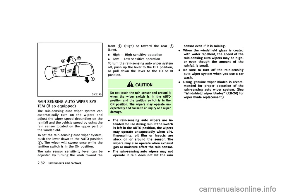
push the lever down to the AUTO position
*1. The wiper will sweep once while the
ignition switch is in the ON position.
The rain sensor sensitivity level can be
adjusted by turning the knob toward the front
*2(High) or toward the rear*3(Low).
.
High —High sensitive operation
. Low —Low sensitive operation
To turn the rain-sensing auto wiper system
off, push up the lever to the OFF position,
or pull down the lever to the LO or HI
position.
CAUTION
Do not touch the rain sensor and around it
when the wiper switch is in the AUTO
position and the ignition switch is in the
ON position. The wipers may operate un-
expectedly and cause to an injury or a wiper
damage.
. The rain-sensing auto wipers are in-
tended for use during rain. If the switch
is left in the AUTO position, the wipers
may operate unexpectedly when dirt,
fingerprints, oil film or insects are
stuck on or around the sensor. The
wipers may also operate when exhaust
gas or moisture affect the rain sensor.
. The rain-sensing auto wipers may not
operate if rain does not hit the rain sensor even if it is raining.
. When the windshield glass is coated
with water repellent, the speed of the
rain-sensing auto wipers may be high-
er even though the amount of the
rainfall is small.
. Be sure to turn off the rain-sensing
auto wiper system when you use a car
wash.
. Using genuine wiper blades is recom-
mended for proper operation of the
rain-sensing auto wiper system. (See
“Windshield wiper blades” (P.8-20) for
wiper blade replacement.)
Page 106 of 474
SIC4192
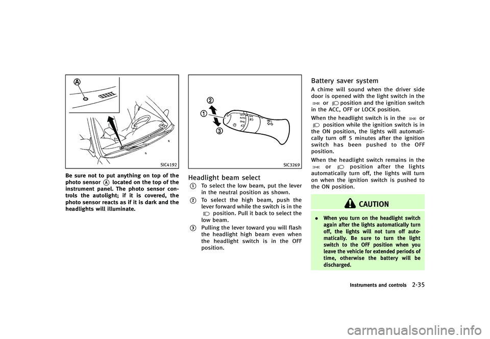
Be sure not to put anything on top of the
photo sensor
*Alocated on the top of the
instrument panel. The photo sensor con-
trols the autolight; if it is covered, the
photo sensor reacts as if it is dark and the
headlights will illuminate.
SIC3269
Headlight beam selectGUID-A356FC5F-5977-428C-9511-7C0A81EB4995*1To select the low beam, put the lever
in the neutral position as shown.
*2To select the high beam, push the
lever forward while the switch is in the
position. Pull it back to select the
low beam.
*3Pulling the lever toward you will flash
the headlight high beam even when
the headlight switch is in the OFF
position.
Battery saver systemGUID-F8729D36-FA75-4013-8DEE-B286CA93AFCAA chime will sound when the driver side
door is opened with the light switch in the
orposition and the ignition switch
in the ACC, OFF or LOCK position.
When the headlight switch is in the
orposition while the ignition switch is in
the ON position, the lights will automati-
cally turn off 5 minutes after the ignition
switch has been pushed to the OFF
position.
When the headlight switch remains in the
orposition after the lights
automatically turn off, the lights will turn
on when the ignition switch is pushed to
the ON position.
CAUTION
. When you turn on the headlight switch
again after the lights automatically turn
off, the lights will not turn off auto-
matically. Be sure to turn the light
switch to the OFF position when you
leave the vehicle for extended periods of
time, otherwise the battery will be
discharged.
Instruments and controls2-35
Page 165 of 474
3-36Pre-driving checks and adjustments
The indicator light will turn off. Push the“I”
switch
*Dto turn the system on.
Do not allow any object to cover the
sensors
*Eor apply glass cleaner on
them. Doing so will reduce the sensitivity
of the sensor, resulting in improper
operation.
For the HomeLink
®Universal Transceiver (if
so equipped) operation, see “HomeLink®
Universal Transceiver”(P.2-53).
SPA2309
OUTSIDE MIRRORSGUID-6F52A95C-0B73-41C8-998E-F096A254E170
WARNING
Objects viewed in the outside mirror on the
passenger side are closer than they appear.
Be careful when moving to the right. Using
only this mirror could cause an accident.
Use the inside mirror or glance over your
shoulder to properly judge distances to
other objects.
Adjusting outside mirrorsGUID-F6C40348-C87B-475F-A9A3-73964F05FB99The outside mirror control switch is located
on the armrest.
The outside mirror will operate only when
the ignition switch is in the ACC or ON
position.
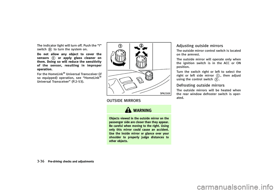
Turn the switch right or left to select the
right or left side mirror
*1, then adjust
using the control switch
*2.
Defrosting outside mirrorsGUID-C468B597-65A8-40CE-9C16-2935D2F48E8FThe outside mirrors will be heated when
the rear window defroster switch is oper-
ated.
Page 207 of 474
4-36Monitor, climate, audio, phone and voice recognition systems
perature is above 238F (−58C) to
defog the windshield. The air recir-
culation mode will automatically
turn off. The outside air circulation
mode will be selected to improve the
defogging performance.
Manual operationGUID-04AA3772-8A3E-4810-97DF-F91772D228AFThe manual mode can be used to control
the heater and air conditioner to your
desired settings.
To turn off the heater and air conditioner,
push the“OFF”button.
Fan speed control:
GUID-D73A39BF-43C8-459F-9C24-47B7F579C407Push the fan speed control button “”to
increase the fan speed.
Push the fan speed control button “
”to
decrease the fan speed.
Push the “AUTO”button to change the fan
speed to the automatic mode. Air flow control:
GUID-D73A39BF-43C8-459F-9C24-47B7F579C407Push the
“MODE”button to change the air
flow mode.
: Air flows from the center and side ventila- tors.
: Air flows from the center and side ventila-tors, and foot outlets.
: Air flows mainly from the foot outlets.
: Air flows from the defroster and footoutlets.
Temperature control:GUID-D73A39BF-43C8-459F-9C24-47B7F579C407Turn the temperature control dial to set the
desired temperature.
.The temperature can be set within the
following range.
— For U.S.: 60 to 908F (16 to 328C)
— For Canada: 64 to 908F (18 to 328C)
Air recirculation:
GUID-D73A39BF-43C8-459F-9C24-47B7F579C407Push the intake air control button to
recirculate interior air inside the vehicle.
The indicator light on the “
”side will
illuminate.
The air recirculation mode cannot be
activated when the air conditioner is in
the front defrosting mode “
”.Outside air circulation:
GUID-D73A39BF-43C8-459F-9C24-47B7F579C407Push the intake air control button to draw
outside air into the passenger compart-
ment.
The indicator light on the
“
”side and
“” side will turn off.
Automatic intake air control:
GUID-D73A39BF-43C8-459F-9C24-47B7F579C407In the AUTO mode, the intake air will be
controlled automatically. To manually con-
trol the intake air, push the intake air
control button.
To return to the automatic control mode,
push the intake air control button until the
indicator light on the “
”side illumi-
nates. The advanced climate control sys-
tem turns on and the intake air will be
controlled automatically.
To turn system offGUID-4BE2C565-51C3-4AA2-91D6-69A80D4BEE3EPush the OFF button.
Advanced climate control systemGUID-5F68BE68-BCD7-4189-97D3-A21DBC936BB0The advanced climate control system keeps
the air inside of the vehicle clean, using
the ion control and the automatic air intake
control with outside odor and exhaust gas
detecting sensor.
Page 208 of 474
SAA2734
Models with navigation system
SAA2735
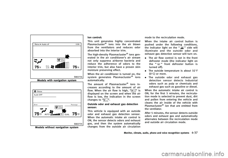
Models without navigation systemIon control:
GUID-D73A39BF-43C8-459F-9C24-47B7F579C407This unit generates highly concentrated
Plasmacluster®ions into the air blown
from the ventilators and reduces odor
absorbed into the interior trim.
The high-density Plasmacluster
®ions gen-
erated in the air conditioner’s air stream
not only suppress airborne bacteria and
reduce the adherence of odors to the
interior trim, but also have a proven skin
moisture preserving effect.
When the air conditioner is turned on, the
system generates Plasmacluster
®ions
automatically.
The amount of Plasmacluster
®ions in-
creases according to the amount of air
flow. When the air flow is high, “
”is
displayed on the screen and when the air
flow is low, the indication in the screen
changes to “
”.
Outside odor and exhaust gas detection
sensor:
GUID-D73A39BF-43C8-459F-9C24-47B7F579C407This vehicle is equipped with an outside
odor and exhaust gas detection sensor.
When the automatic intake air control is
ON, the sensor detects odors and exhaust
gas, and then the system automatically
changes from the outside air circulation mode to the recirculation mode.
When the intake air control button is
pushed under the following conditions,
the indicator light on the
“
”side will
illuminate and the outside odor and
exhaust gas detection sensor will turn on.
. The air flow control is not in the front
defroster mode (the indicator light on
the “
”front defroster button is
turned off).
. The outside temperature is about 328F
(08C) or more.
. The outside odor and exhaust gas
detection sensor detects industrial
odors such as pulp or chemicals and
exhaust gas such as gasoline or diesel.
When the automatic intake air control is
ON, for the first 5 minutes, the recircula-
tion mode is selected to prevent dust, dirt
and pollen from entering the vehicle and
cleans the air inside of the vehicle with
Plasmacluster
®ion that are emitted from
the ventilator.
After 5 minutes, the sensor detects outside
odors and exhaust gas and automatically
alternates between the recirculation mode
and outside air circulation mode.
Monitor, climate, audio, phone and voice recognition systems4-37
Page 209 of 474
4-38Monitor, climate, audio, phone and voice recognition systems
OPERATING TIPSGUID-49AF0854-A2A0-4F7D-B7F0-98CA4B08BF2EWhen the engine coolant temperature and
outside air temperature are low, the air
flow from the foot outlets may not operate
for a maximum of 150 seconds. This is not
a malfunction. After the coolant tempera-
ture warms up, air will flow normally from
the foot outlets.
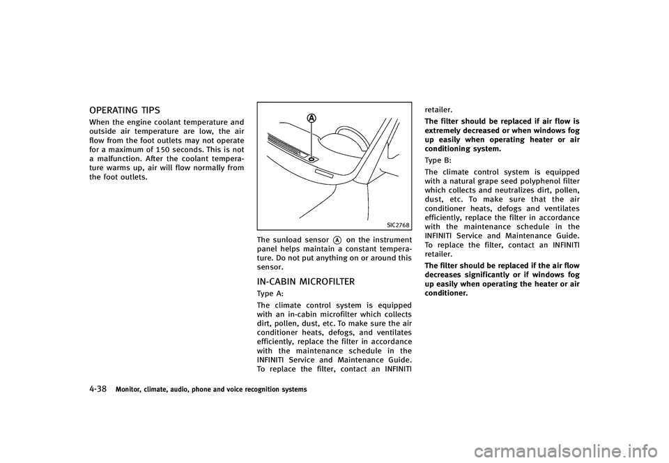
SIC2768
The sunload sensor*Aon the instrument
panel helps maintain a constant tempera-
ture. Do not put anything on or around this
sensor.
IN-CABIN MICROFILTERGUID-070CF22D-F703-4656-9B6D-17B643627103Type A:
The climate control system is equipped
with an in-cabin microfilter which collects
dirt, pollen, dust, etc. To make sure the air
conditioner heats, defogs, and ventilates
efficiently, replace the filter in accordance
with the maintenance schedule in the
INFINITI Service and Maintenance Guide.
To replace the filter, contact an INFINITI retailer.
The filter should be replaced if air flow is
extremely decreased or when windows fog
up easily when operating heater or air
conditioning system.
Type B:
The climate control system is equipped
with a natural grape seed polyphenol filter
which collects and neutralizes dirt, pollen,
dust, etc. To make sure that the air
conditioner heats, defogs and ventilates
efficiently, replace the filter in accordance
with the maintenance schedule in the
INFINITI Service and Maintenance Guide.
To replace the filter, contact an INFINITI
retailer.
The filter should be replaced if the air flow
decreases significantly or if windows fog
up easily when operating the heater or air
conditioner.
Page 315 of 474

5-6Starting and driving
.When a spare tire is mounted or a wheel
is replaced, the TPMS will not function
and the low tire pressure warning light
will flash for approximately 1 minute.
The light will remain on after 1 minute.
Contact your INFINITI retailer as soon as
possible for tire replacement and/or
system resetting.
. Replacing tires with those not originally
specified by INFINITI could affect the
proper operation of the TPMS.
. Do not inject any tire liquid or aerosol
tire sealant into the tires, as this may
cause a malfunction of the tire pressure
sensors (for models not equipped with
the emergency tire puncture repair kit).
. If you used the Emergency Tire Sealant
to repair a minor tire puncture, your
INFINITI retailer will also need to replace
the TPMS sensor in addition to repairing
or replacing the tire (for models
equipped with the emergency tire punc-
ture repair kit).
. INFINITI recommends using only INFINITI
Genuine Emergency Tire Sealant pro-
vided with your vehicle. Other tire
sealants may damage the valve stem
seal which can cause the tire to lose air pressure (for models equipped with the
emergency tire puncture repair kit).
CAUTION
.
The TPMS may not function properly
when the wheels are equipped with tire
chains or the wheels are buried in snow.
. Do not place metalized film or any metal
parts (antenna, etc.) on the windows.
This may cause poor reception of the
signals from the tire pressure sensors,
and the TPMS will not function properly.
Some devices and transmitters may tem-
porarily interfere with the operation of the
TPMS and cause the low tire pressure
warning light to illuminate. Some exam-
ples are:
.Facilities or electric devices using simi-
lar radio frequencies are near the
vehicle.
. If a transmitter set to similar frequen-
cies is being used in or near the
vehicle.
. If a computer (or similar equipment) or
a DC/AC converter is being used in or near the vehicle.
FCC Notice:
For USA:
This device complies with Part 15 of the
FCC Rules. Operation is subject to the
following two conditions: (1) This device
may not cause harmful interference, and
(2) this device must accept any interfer-
ence received, including interference that
may cause undesired operation.
Note: Changes or modifications not ex-
pressly approved by the party responsible
for compliance could void the user’s
authority to operate the equipment.
For Canada:
This device complies with RSS-210 of
Industry Canada. Operation is subject to
the following two conditions: (1) this
device may not cause interference, and
(2) this device must accept any interfer-
ence, including interference that may
cause undesired operation of the device.
Page 334 of 474

SSD0662
Type A
SSD1169
Type B
PRECAUTIONS ON VEHICLE-TO-VE-
HICLE DISTANCE CONTROL MODE
GUID-9966B4DC-07EB-4AC3-A4FD-BEAF6B7FD5F3The system is intended to enhance the
operation of the vehicle when following a
vehicle traveling in the same lane and
direction.
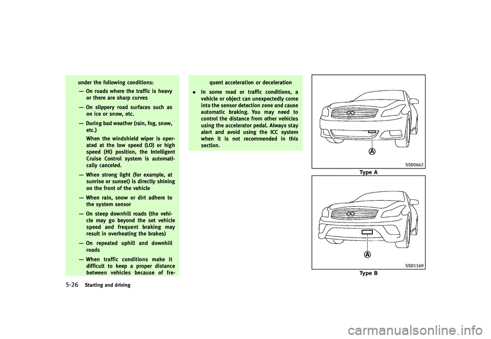
If the distance sensor
*Adetects a slower
moving vehicle ahead, the system will
reduce the vehicle speed so that your
vehicle follows the vehicle in front at the
selected distance.
The system automatically controls the
throttle and applies the brakes (up to
25% of vehicle braking power) if neces-
sary.
The detection range of the sensor is
approximately 390 ft (120 m) ahead.
The distance sensor will not detect under
most conditions:
. Stationary and slow moving vehicles
. Pedestrians or objects in the roadway
. Oncoming vehicles in the same lane
. Motorcycles traveling offset in the travel
lane This system will not automatically brake
the vehicle to a stop.
WARNING
.
As there is a performance limit to the
distance control function, never rely
solely on the Intelligent Cruise Control
system. This system does not correct
careless, inattentive or absent-minded
driving, or overcome poor visibility in
rain, fog, or other bad weather. Decele-
rate the vehicle speed by depressing the
brake pedal, depending on the distance
to the vehicle ahead and the surround-
ing circumstances in order to maintain a
safe distance between vehicles.
. Although the brake operation is con-
trolled by the system, the system does
not automatically stop the vehicle. If the
vehicle speed falls below approximately
20 MPH (32 km/h), the Intelligent Cruise
Control system is automatically canceled
and a warning chime sounds. (The brake
control is also canceled.)
. The system may not detect the vehicle in
front of you in certain road or weather
conditions. To avoid accidents, never use
the Intelligent Cruise Control system
Starting and driving5-25
Page 335 of 474
5-26Starting and driving
under the following conditions:
—On roads where the traffic is heavyor there are sharp curves
—On slippery road surfaces such ason ice or snow, etc.
—During bad weather (rain, fog, snow,
etc.)
When the windshield wiper is oper-
ated at the low speed (LO) or high
speed (HI) position, the Intelligent
Cruise Control system is automati-
cally canceled.
—When strong light (for example, atsunrise or sunset) is directly shining
on the front of the vehicle
—When rain, snow or dirt adhere tothe system sensor
—On steep downhill roads (the vehi-
cle may go beyond the set vehicle
speed and frequent braking may
result in overheating the brakes)
—On repeated uphill and downhillroads
—When traffic conditions make itdifficult to keep a proper distance
between vehicles because of fre- quent acceleration or deceleration
. In some road or traffic conditions, a
vehicle or object can unexpectedly come
into the sensor detection zone and cause
automatic braking. You may need to
control the distance from other vehicles
using the accelerator pedal. Always stay
alert and avoid using the ICC system
when it is not recommended in this
section.
SSD0662
Type A
SSD1169
Type B
Page 336 of 474
VEHICLE-TO-VEHICLE DISTANCE
CONTROL MODE OPERATION
GUID-C59C0E1C-58CB-446E-BFDE-56FE6CA41124Always pay attention to the operation of
the vehicle and be ready to manually
control the proper following distance. The
vehicle-to-vehicle distance control mode of
the Intelligent Cruise Control (ICC) system
may not be able to maintain the selected
distance between vehicles (following dis-
tance) or selected vehicle speed under
some circumstances.
The vehicle-to-vehicle distance control
mode uses a sensor
*Alocated on the
front of the vehicle to detect vehicles
traveling ahead. The sensor generally
detects the signals returned from the
reflectors on a vehicle ahead. Therefore, if
the sensor cannot detect the reflector on
the vehicle ahead, the ICC system may not
maintain the selected distance.
The following are some conditions in which
the sensor cannot detect the signals:
. When the reflector of the vehicle ahead
is positioned high on the vehicle
(trailer, etc.)
. When the reflector on the vehicle ahead
is missing, damaged or covered .
When the reflector of the vehicle ahead
is covered with dirt, snow and road
spray
. When the snow or road spray from
traveling vehicles reduces the sensor’s
visibility
. When dense exhaust or other smoke
(black smoke) from vehicles reduces
the sensor’s visibility
. When excessively heavy baggage is
loaded in the rear seat or the trunk of
your vehicle
The ICC system is designed to automati-
cally check the sensor’s operation within
the limitations of the system. When the
sensor is covered with dirt or obstructs, the
system will automatically be canceled. If
the sensor is covered with ice, a transpar-
ent or translucent vinyl bag, etc., the ICC
system may not detect them. In these
instances, the vehicle-to-vehicle distance
control mode may not cancel and may not
be able to maintain the selected following
distance from the vehicle ahead. Be sure to
check and clean the sensor regularly.
The vehicle-to-vehicle distance control
mode is designed to maintain a selected
distance and reduce the speed to match
the slower vehicle ahead; the system will decelerate the vehicle as necessary. How-
ever, the ICC system can only apply up to
25% of the vehicles total braking power.
This system should only be used when
traffic conditions allow vehicle speeds to
remain fairly constant or when vehicle
speeds change gradually. If a vehicle
moves into the traveling lane ahead or if
a vehicle traveling ahead rapidly decele-
rates, the distance between vehicles may
become closer because the ICC system
cannot decelerate the vehicle quickly en-
ough. If this occurs, the ICC system will
sound a warning chime and blink the
system display to notify the driver to take
necessary action.
The system will cancel and a warning
chime will sound if the speed falls below
approximately 20 MPH (32 km/h). The
system will also disengage below the 20
MPH (32 km/h) cut-off speed or over the
maximum set speed.
See
“Approach warning” (P.5-37).
The following items are controlled in the
vehicle-to-vehicle distance control mode:
. When there are no vehicles traveling
ahead, the vehicle-to-vehicle distance
control mode maintains the speed set
by the driver. The set speed range is
Starting and driving5-27