headlights INFINITI G35 2003 Owners Manual
[x] Cancel search | Manufacturer: INFINITI, Model Year: 2003, Model line: G35, Model: INFINITI G35 2003Pages: 256, PDF Size: 3.37 MB
Page 54 of 256

2 Instruments and controls Instrument panel ....................................................... 2-2
Meters and gauges ................................................... 2-3
Speedometer and odometer ................................ 2-4
Tachometer .......................................................... 2-4
Engine coolant temperature gauge ...................... 2-5
Fuel gauge ........................................................... 2-5
Compass display ...................................................... 2-6
Warning/indicator lights and audible reminders ........ 2-9
Checking bulbs ..................................................... 2-9
Warning lights....................................................... 2-9
Indicator lights .................................................... 2-11
Audible reminders .............................................. 2-13
Security systems ..................................................... 2-13
Vehicle security system ...................................... 2-13
Infiniti Vehicle Immobilizer System ................... 2-14
Windshield wiper and washer switch ...................... 2-16
Rear window and outside mirror (if so equipped)
defroster switch ....................................................... 2-16
Headlight and turn signal switch ............................. 2-17
Xenon headlights (if so equipped) ..................... 2-17
Headlight switch ................................................. 2-17
Turn signal switch .............................................. 2-19
Fog light switch ....................................................... 2-20
Hazard warning flasher switch ................................ 2-20 Horn......................................................................... 2-21
Heated seats (if so equipped) ................................. 2-21
Vehicle dynamics control (VDC) off switch ............ 2-22
Clock ....................................................................... 2-23
Adjusting the time............................................... 2-23
Power outlet ............................................................ 2-23
Cigarette lighter and ashtray (accessory) ............... 2-24
Storage .................................................................... 2-25
Instrument pocket (Except for Navigation system
equipped models) ............................................... 2-25
Pocket (Manual transmission model) ................. 2-25
Glasses case ...................................................... 2-26
Cup holder .......................................................... 2-26
Glove box ........................................................... 2-27
Upper glove box (Except for Navigation system
equipped models) ............................................... 2-28
Console box ....................................................... 2-28
Rear armrest pocket ........................................... 2-29
Cargo net............................................................ 2-29
Coat hook (Coupe) ............................................. 2-30
Stowing golf bags ............................................... 2-30
Windows .................................................................. 2-31
Power windows .................................................. 2-31
Automatic adjusting function (Coupe) ................ 2-33
Z 02.7.29/V35-D/V5.0
X
Page 68 of 256

How to activate the vehicle security
system 1. Close all windows.
The system can be activated even if the
windows are open.
2. Remove the key from the ignition switch.
3. Close and lock all doors, hood and trunk lid.
Lock all doors by pressing the LOCK button
on the keyfob. When using the keyfob, the
hazard indicators flash twice to indicate all
doors are locked. 4. Confirm that the SECURITY indicator light
comes on. The SECURITY indicator light
glows for about 30 seconds and then blinks.
The system is now activated. If, during this
30 second time period, the door is unlocked
by the key or the keyfob, or the ignition key
is turned to ACC or ON, the system will not
activate.
Even when the driver and/or passengers
are in the vehicle, the system will activate
with all doors, hood and trunk lid locked
and ignition key off. Turn the ignition key to
ACC to turn off the system.
Vehicle security system operation The security system will give the following
alarm:
O The headlights blink and the horn sounds
intermittently.
O The alarm automatically turns off after ap-
proximately 1 minute. However, the alarm
reactivates if the vehicle is tampered with
again. The alarm can be shut off by unlock-
ing a door with the key, or by pressing the
UNLOCK button on the keyfob.
The alarm is activated by:
O Opening the door without using the key or
keyfob. O Opening the trunk lid without using the key
or keyfob.
O Opening the hood.
How to stop alarm The alarm will stop only by unlocking a door
with the key, or by pressing the UNLOCK
button on keyfob. The alarm will not stop if the
ignition switch is turned to ACC or ON.
If the system does not operate as de-
scribed above, have it checked by your
INFINITI retailer.
INFINITI VEHICLE IMMOBILIZER
SYSTEM The Infiniti Vehicle Immobilizer System will not
allow the engine to start without the use of the
registered Infiniti Vehicle Immobilizer System
key.
If the engine fails to start using the registered
Infiniti Vehicle Immobilizer System key, it may
be due to interference caused by another
Infiniti Vehicle Immobilizer System key, an
automated toll road device or automated pay-
ment device on the key ring. Restart the en-
gine using the following procedures:
1. Leave the ignition switch in the ON position
for approximately 5 seconds.SIC1442
2-14 Instruments and controls
Z 02.7.29/V35-D/V5.0
X
Page 71 of 256

XENON HEADLIGHTS (if so
equipped)
WARNING HIGH VOLTAGE
O When xenon headlights are on, they
produce a high voltage. To prevent an
electric shock, never attempt to
modify or disassemble. Always have
your xenon headlights replaced at an authorized INFINITI retailer.
O Xenon headlights provide consider-
ably more light than conventional
headlights. If they are not correctly
aimed, they might temporarily blind
an oncoming driver or the driver
ahead of you and cause a serious
accident. If headlights are not aimed
correctly, immediately take your ve-
hicle to an authorized INFINITI retailer
and have the headlights adjusted
correctly. When the xenon headlight is initially turned on,
its brightness or color varies slightly. However,
the color and brightness will soon stabilize.
O The life of xenon headlights will be
shortened by frequent on-off operation.
It is generally desirable not to turn off
the headlights for short intervals (for
example, when the vehicle stops at a
traffic signal). Even when the daytime
running lights are active (Canada only),
the xenon headlights do not turn on.
This way the life of the xenon headlights
is not reduced.
O If a xenon headlight bulb is close to
burning out, the brightness will drasti-
cally decrease, the light will start blink-
ing, or the color of the light will become
reddish. If one or more of the above
signs appear, contact an INFINITI re-
tailer.
HEADLIGHT SWITCH
Lighting Turn the switch to the AUTO position:
When the ignition key is in the ON position, the
tail lights, headlights, instrument lights and
other lights turn on automatically, depending
on the brightness of the surroundings. The SIC1834
HEADLIGHT AND TURN SIGNAL
SWITCH
Instruments and controls
2-17
Z 02.7.29/V35-D/V5.0
X
Page 72 of 256

headlights will automatically turn off 5 minutes
after the ignition switch is turned to the OFF
position and the driver's or front passenger's
door is opened.
The headlight will also automatically turn off 45
seconds after a front door is opened and
closed.
When the light switch is turned to the po-
sition, the headlight low or high beam will turn
off.
Turn the switch to the position:
The front clearance, side marker, tail, license
plate and instrument lights will come on.
Turn the switch to the position:
Headlights will come on and all the other lights
remain on. Be sure not to put anything on top of the
photo sensor located on the top left-hand
side of the instrument panel. The photo
sensor controls the autolamp; if it is cov-
ered, the photo sensor reacts as if it is dark
and the headlights will illuminate.
Battery saver system O When the headlight switch is in the or
position while the ignition switch is in
the ON position, the lights (including the
front fog light) will automatically turn off 5
minutes after the ignition switch has been
turned to the OFF position. O When the headlight switch remains in the
or position after the lights auto-
matically turn off, the lights will turn on for 5
minutes when the headlight switch is turned
to the OFF position and turn to the or
position.
CAUTION O Be sure to turn the light switch to the
OFF position when you leave the ve-
hicle for extended periods of time,
otherwise the battery will go dead.
O Never leave the light switch on when
the engine is not running for ex-
tended periods of time even if the
headlights turn off automatically. SIC1230
2-18 Instruments and controls
Z 02.7.29/V35-D/V5.0
X
Page 73 of 256

Instrument brightness control The instrument brightness control operates
when the light switch is in the or
position.
Turn the control to adjust the brightness of
instrument panel lights and clock (except
power window switch lights).
When the control is turned upward until it
stops, the light intensity will be at maximum.
When the control is turned downward until it
stops, the light will be turned off. Headlight beam select To select the high beam, push the lever for-
ward. Pull it back to select the low beam.
Flashing signal Pulling the lever toward you will flash the
headlight high beam.
Daytime running light system
(Canada only) The headlights automatically illuminate at a
reduced intensity when the engine is started
with the parking brake released. The daytime
running lights operate with the headlight switch
in the OFF position or in the position.
Turn the headlight switch to the position
for full illumination when driving at night.
If the parking brake is applied before the
engine is started, the daytime running lights do
not illuminate. The daytime running lights illu-
minate once the parking brake is released.
The daytime running lights will remain on until
the ignition switch is turned off. WARNING When the daytime running light system
is active, tail lights on your vehicle are
not on. It is necessary at dusk to turn on
your headlights. Failure to do so could
cause an accident injuring yourself and
others.
TURN SIGNAL SWITCH
Turn signal Move the lever up or down to signal the turning
direction. When the turn is completed, the turn
signals cancel automatically.
Lane change signal To indicate a lane change, move the lever up
or down to the point where lights begin flash-
ing.SIC0922
Instruments and controls
2-19
Z 02.7.29/V35-D/V5.0
X
Page 74 of 256

To turn the fog lights on, turn the headlight
switch to the position, then turn the
switch to the position. To turn them off,
turn the switch to the OFF position.
The headlights must be on for the fog lights to
operate. Push the switch on to warn other drivers when
you must stop or park under emergency con-
ditions. All turn signal lights will flash.
Some state or provincial laws may prohibit
the use of the hazard warning flasher
switch while driving.
WARNING O If stopping for an emergency, be sure
to move the vehicle well off the road. O Do not use the hazard warning flash-
ers while moving on the highway un-
less unusual circumstances force
you to drive so slowly that your ve-
hicle might become a hazard to other
traffic.
O Turn signals do not work when the
hazard warning flasher lights are on.
The flasher can be actuated with the ignition
switch either off or on.SIC1836 SIC1447
FOG LIGHT SWITCH
HAZARD WARNING FLASHER
SWITCH
2-20 Instruments and controls
Z 02.7.29/V35-D/V5.0
X
Page 77 of 256

If the power supply is disconnected, the
clock will not indicate the correct time.
Readjust the time.
ADJUSTING THE TIME To adjust the time, turn the adjusting knob. The power outlet is for powering electrical
accessories such as cellular telephones.
CAUTION O Use caution as the socket and plug
may be hot during or immediately
after use.
O This power outlet is not designed for
use with a cigarette lighter unit.
O Do not use with accessories that ex-
ceed a 12 volt, 120W (10A) power draw. Do not use double adapters or
more than one electrical accessory.
O Use this power outlet with the engine
running. (If the engine is stopped,
this could result in a discharged bat-
tery.)
O Avoid using when the air conditioner,
headlights or rear window defogger
is on.
O Before inserting or disconnecting a
plug, be sure to turn off the powerSIC1855 SIC1840A SIC1803
CLOCK POWER OUTLET
Instruments and controls
2-23
Z 02.7.29/V35-D/V5.0
X
Page 102 of 256

Continue to press the UNLOCK button for 3
seconds. All the door windows will be lowered.
Continue to press the UNLOCK button until
windows are fully open.
To stop lowering the windows, release the
UNLOCK button.
To start lowering the windows, press the UN-
LOCK button again for more than 3 seconds.
The rear door windows will operate 0.5 sec-
onds after the front windows' operation (if so
equipped).
Releasing the trunk lid 1. Push the TRUNK button on the keyfob for
longer than 0.5 seconds with the key re-
moved from the ignition key cylinder.
2. The trunk lid opens.
Using the panic alarm If you are near your vehicle and feel threat-
ened, you may activate the alarm to call atten-
tion as follows:
1. Push the PANIC button on the keyfob for
longer than 0.5 seconds with the key
removed from the ignition key cylinder.
2. The theft warning alarm and headlights will
stay on for 30 seconds. 3. The panic alarm stops when:
O It has run for 30 seconds, or
O The LOCK or the UNLOCK button is
pressed, or
O The PANIC or the TRUNK button is pushed
on the keyfob for longer than 0.5 seconds.
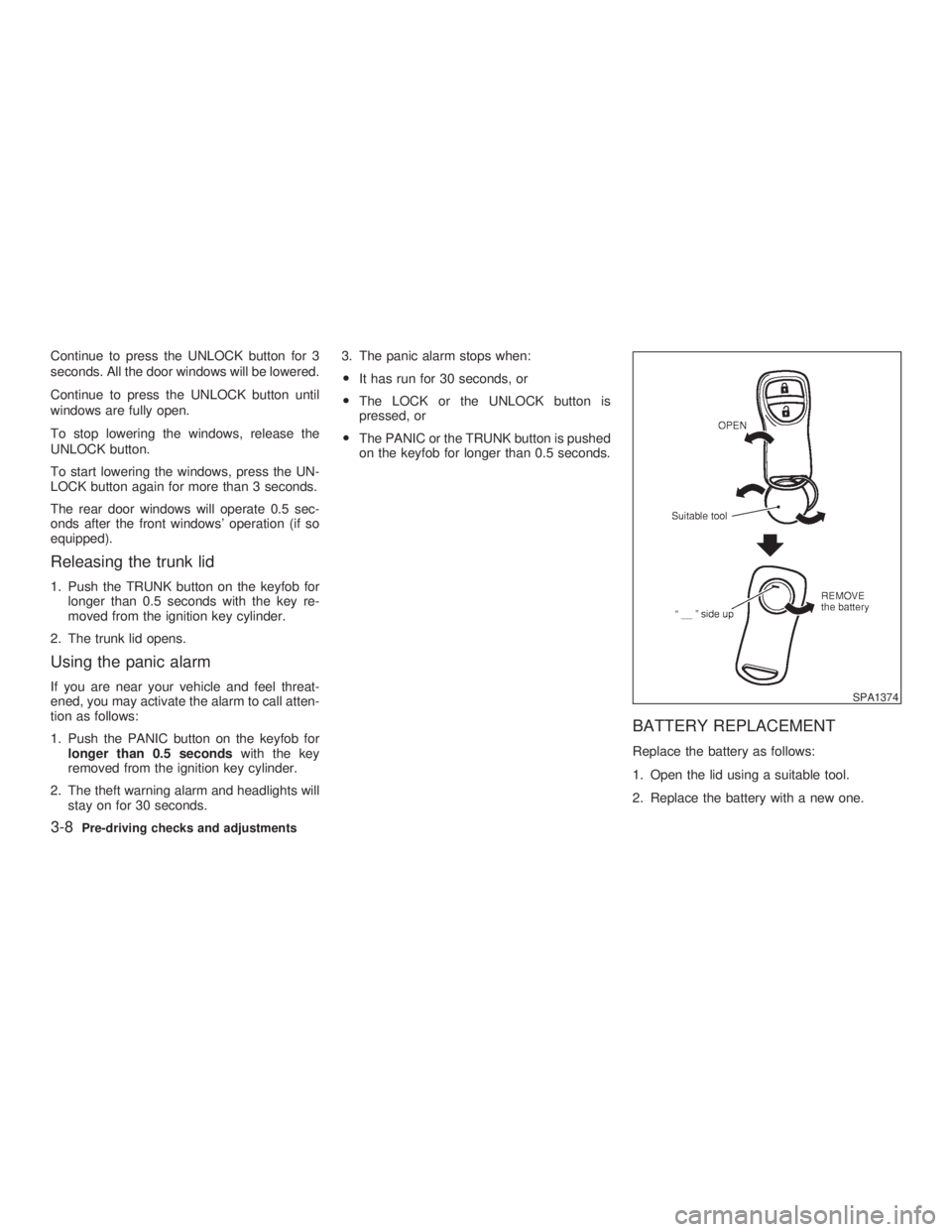
BATTERY REPLACEMENT Replace the battery as follows:
1. Open the lid using a suitable tool.
2. Replace the battery with a new one. SPA1374
3-8 Pre-driving checks and adjustments
Z 02.11.1/V35-D/V5.0
X
Page 111 of 256

CAUTIONStore the main sun visor after storing
the extension sun visor.
AUTOMATIC ANTI-GLARE INSIDE
MIRROR (if so equipped)
WARNING Use the AUTO position only when nec-
essary, because it reduces rear view
clarity.
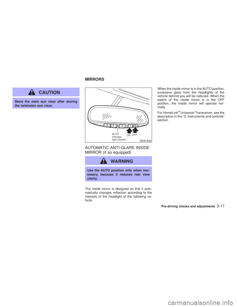
The inside mirror is designed so that it auto-
matically changes reflection according to the
intensity of the headlight of the following ve-
hicle. When the inside mirror is in the AUTO position,
excessive glare from the headlights of the
vehicle behind you will be reduced. When the
switch of the inside mirror is in the OFF
position, the inside mirror will operate nor-
mally.
For HomeLink Universal Transceiver, see the
description in the ª2. Instruments and controlsº
section. SPA1430
MIRRORS
Pre-driving checks and adjustments
3-17
Z 02.7.29/V35-D/V5.0
X
Page 179 of 256

8 Do-it-yourself Maintenance precautions .......................................... 8-2
Engine compartment check locations ....................... 8-4
Engine cooling system .............................................. 8-5
Checking engine coolant level ............................. 8-5
Changing engine coolant ..................................... 8-6
Engine oil .................................................................. 8-7
Checking engine oil level ..................................... 8-7
Changing engine oil and filter .............................. 8-8
Automatic transmission fluid ................................... 8-10
Power steering fluid ................................................ 8-10
Brake and clutch fluid ............................................. 8-11
Brake fluid .......................................................... 8-11
Clutch fluid.......................................................... 8-11
Window washer fluid ............................................... 8-12
Battery ..................................................................... 8-13
Jump starting ...................................................... 8-14
Drive belts ............................................................... 8-14
Spark plugs ............................................................. 8-15
Replacing spark plugs ........................................ 8-15
Air cleaner ............................................................... 8-16
Windshield wiper blades ......................................... 8-16
Cleaning ............................................................. 8-16
Replacing............................................................ 8-17 Parking brake and brake pedal ............................... 8-18
Checking parking brake ..................................... 8-18
Checking brake pedal ........................................ 8-18
Brake booster ..................................................... 8-19
Fuses....................................................................... 8-20
Engine compartment .......................................... 8-20
Passenger compartment .................................... 8-21
Keyfob battery replacement .................................... 8-21
Lights ....................................................................... 8-23
Headlights........................................................... 8-25
Exterior and interior lights .................................. 8-26
Wheels and tires ..................................................... 8-30
Tire pressure ...................................................... 8-30
Types of tires...................................................... 8-30
Tire chains .......................................................... 8-31
Changing wheels and tires ................................. 8-32
Z 02.7.29/V35-D/V5.0
X