coolant temperature INFINITI G35 2006 Owners Manual
[x] Cancel search | Manufacturer: INFINITI, Model Year: 2006, Model line: G35, Model: INFINITI G35 2006Pages: 344, PDF Size: 6.81 MB
Page 17 of 344
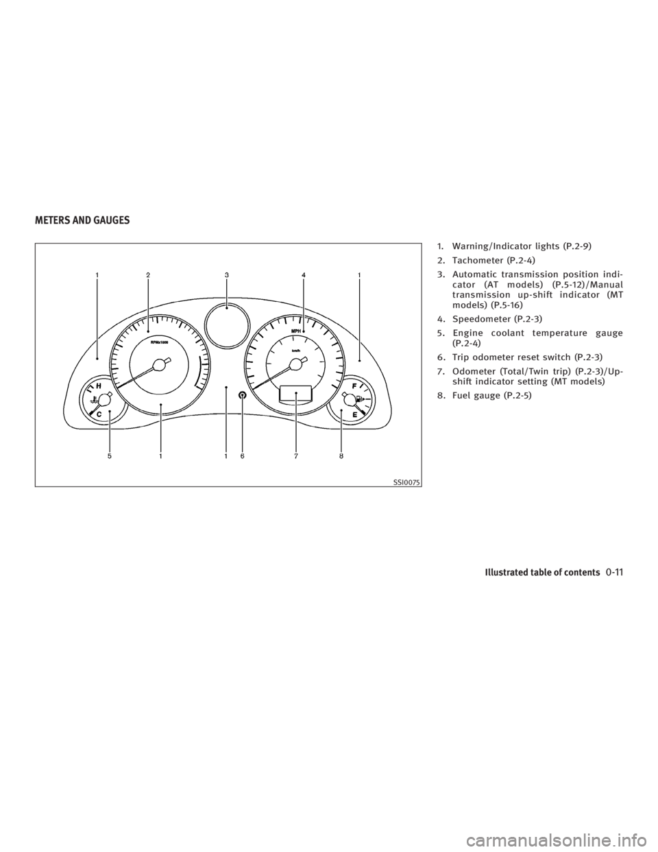
1. Warning/Indicator lights (P.2-9)
2. Tachometer (P.2-4)
3. Automatic transmission position indi-
cator (AT models) (P.5-12)/Manual
transmission up-shift indicator (MT
models) (P.5-16)
4. Speedometer (P.2-3)
5. Engine coolant temperature gauge
(P.2-4)
6. Trip odometer reset switch (P.2-3)
7. Odometer (Total/Twin trip) (P.2-3)/Up-
shift indicator setting (MT models)
8. Fuel gauge (P.2-5)
SSI0075METERS AND GAUGES
Illustrated table of contents
0-11
w 06.1.4/V35-D/V5.0
X
Page 72 of 344
2 Instruments and controls Instrument panel .............................................. 2-2
Meters and gauges ........................................... 2-3
Speedometer and odometer ........................ 2-3
Tachometer ................................................. 2-4
Engine coolant temperature gauge .............. 2-4
Fuel gauge .................................................. 2-5
Compass display .............................................. 2-6
Warning/indicator lights and audible
reminders ......................................................... 2-9
Checking bulbs ........................................... 2-9
Warning lights............................................. 2-9
Indicator lights .......................................... 2-14
Audible reminders ..................................... 2-16
Security systems ............................................. 2-17
Vehicle security system.............................. 2-17
INFINITI Vehicle Immobilizer System .......... 2-18
Windshield wiper and washer switch .............. 2-19
Rear window and outside mirror defroster
switch ............................................................ 2-20
Headlight and turn signal switch..................... 2-21
Xenon headlights ....................................... 2-21
Headlight switch ........................................ 2-21
Turn signal switch ..................................... 2-24
Fog light switch ......................................... 2-25 Hazard warning flasher switch ........................ 2-25
Horn ............................................................... 2-26
Heated seats .................................................. 2-26
SNOW mode switch (if so equipped) ............... 2-27
Vehicle Dynamic Control (VDC) off switch ....... 2-28
Clock .............................................................. 2-29
Adjusting the time..................................... 2-29
Power outlet ................................................... 2-29
Cigarette lighter and ashtray .......................... 2-30
Front ......................................................... 2-30
Rear .......................................................... 2-30
Storage ........................................................... 2-31
Door pocket .............................................. 2-31
Instrument pocket (except for navigation
system equipped models) .......................... 2-31
Sunglasses holder .................................... 2-32
Cup holder ................................................ 2-32
Glove box .................................................. 2-35
Upper glove box (except for navigation
system equipped models).......................... 2-35
Console box .............................................. 2-36
Rear armrest pocket (Sedan) ..................... 2-37
Card holder (driver's side) ......................... 2-38
Coat hook (Coupe) .................................... 2-38
w 06.1.5/V35-D/V5.0
X
Page 75 of 344
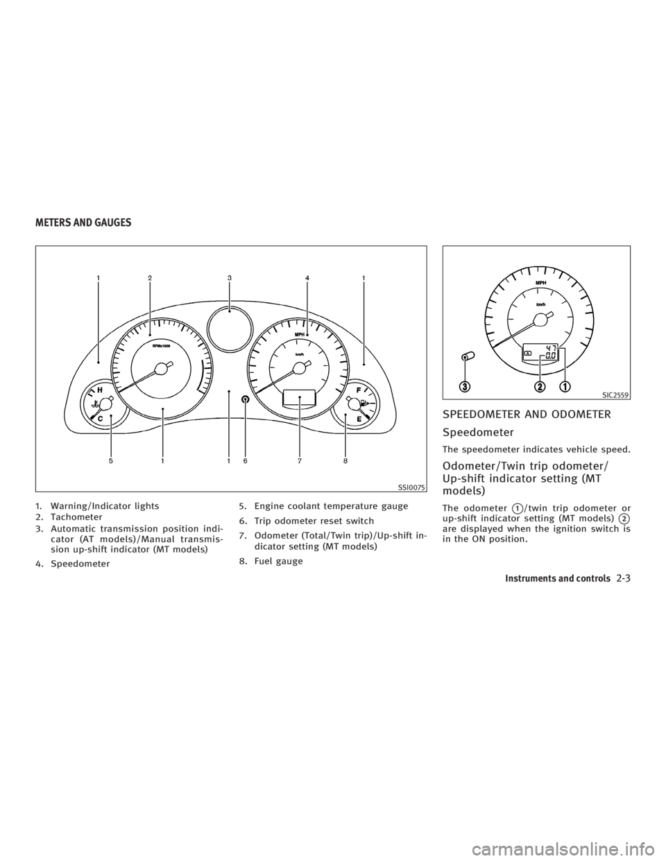
1. Warning/Indicator lights
2. Tachometer
3. Automatic transmission position indi-
cator (AT models)/Manual transmis-
sion up-shift indicator (MT models)
4. Speedometer 5. Engine coolant temperature gauge
6. Trip odometer reset switch
7. Odometer (Total/Twin trip)/Up-shift in-
dicator setting (MT models)
8. Fuel gauge SPEEDOMETER AND ODOMETER
Speedometer The speedometer indicates vehicle speed.
Odometer/Twin trip odometer/
Up-shift indicator setting (MT
models) The odometer
q 1
/twin trip odometer or
up-shift indicator setting (MT models)
q 2
are displayed when the ignition switch is
in the ON position. SSI0075 SIC2559
METERS AND GAUGES
Instruments and controls
2-3
w 06.1.4/V35-D/V5.0
X
Page 76 of 344

The odometer records the total distance
the vehicle has been driven.
The twin trip odometer records the dis-
tance of individual trips.
Changing the display:
Pushing the trip odometer reset switch
q 3
changes the display as follows.
AT models:
TRIP A ! TRIP B ! TRIP A
MT models:
TRIP A ! TRIP B ! Up-shift indicator set-
ting mode ! TRIP A
See ªDriving the vehicleº in the ª5. Start-
ing and drivingº section for the use of the
up-shift indicator.
Resetting the trip odometer:
Pushing the trip odometer reset switch for
more than 1 second resets the trip odom-
eter to zero.
TACHOMETER The tachometer indicates engine speed in
revolutions per minute (rpm). Do not rev
the engine into the red zone
q A
.
CAUTION When engine speed approaches the red
zone, shift to a higher gear. Operating the
engine in the red zone may cause serious en-
gine damage. ENGINE COOLANT TEMPERATURE
GAUGE The gauge indicates the engine coolant
temperature.
The engine coolant temperature is within
the normal range
q A
when the gauge
needle points within the zone shown in
the illustration.
The engine coolant temperature will vary
with the outside air temperature and driv-
ing conditions. SIC2560 SIC2561
2-4 Instruments and controls
w 06.1.4/V35-D/V5.0
X
Page 77 of 344
CAUTIONIf the gauge indicates engine coolant tem-
perature near the hot (H) of the normal
range, reduce vehicle speed to decrease
temperature. If gauge is over the normal
range, stop the vehicle as soon as safely
possible. If the engine is overheated, contin-
ued operation of the vehicle may seriously
damage the engine. See ªIf your vehicle
overheatsº in the ª6. In case of emergencyº
section for immediate action required.
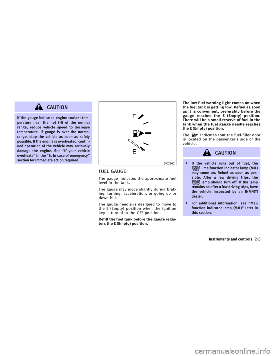
FUEL GAUGE The gauge indicates the approximate fuel
level in the tank.
The gauge may move slightly during brak-
ing, turning, acceleration, or going up or
down hill.
The gauge needle is designed to move to
the E (Empty) position when the ignition
key is turned to the OFF position.
Refill the fuel tank before the gauge regis-
ters the E (Empty) position. The low fuel warning light comes on when
the fuel tank is getting low. Refuel as soon
as it is convenient, preferably before the
gauge reaches the E (Empty) position.
There will be a small reserve of fuel in the
tank when the fuel gauge needle reaches
the E (Empty) position.
The indicates that the fuel-filler door
is located on the passenger's side of the
vehicle.
CAUTION O If the vehicle runs out of fuel, the
malfunction indicator lamp (MIL)
may come on. Refuel as soon as pos-
sible. After a few driving trips, the
lamp should turn off. If the lamp
remains on after a few driving trips, have
the vehicle inspected by an INFINITI
dealer.
O For additional information, see ªMal-
function indicator lamp (MIL)º later in
this section. SIC2562
Instruments and controls
2-5
w 06.1.4/V35-D/V5.0
X
Page 173 of 344

AMBIENT TEMPERATURE The outside ambient temperature will be
shown on the center display.
The ambient temperature sensor is lo-
cated in front of the radiator. The sensor
may be affected by road or engine heat,
wind direction and other driving condi-
tions. The display may differ from the ac-
tual outside temperature or the tempera-
ture displayed on various signs or bill-
boards.
OPERATING TIPS When the engine coolant temperature and
outside air temperature are low, the air
flow from the foot outlets may not operate
for a maximum of 150 seconds. However,
this is not a malfunction. After the coolant
temperature warms up, the air flow from
the foot outlets will operate normally. The sensor
q A
on the instrument panel
helps maintain a constant temperature;
do not put anything on or around this
sensor.
IN-CABIN MICROFILTER The air conditioning system is equipped
with an in-cabin microfilter which collects
dirt, pollen, dust, etc. To make sure air
conditioner heats, defogs, and ventilates
efficiently, replace the filter in accordance
with the maintenance schedule in the
INFINITI Service and maintenance guide.
To replace the filter, contact an INFINITI
dealer. The filter should be replaced if air flow de-
creases significantly or if windows fog up
easily when operating the heater or air
conditioning system.
HA1011-A
Display screen, heater, air conditioner and audio systems
4-13
w 06.1.4/V35-D/V5.0
X
Page 224 of 344
WARNINGDo not use the cruise control when driving
under the following conditions:
O When it is not possible to keep the ve-
hicle at a set speed.
O In heavy traffic or in traffic that varies in
speed.
O On winding or hilly roads.
O On slippery roads (rain, snow, ice, etc.).
O In very windy areas.
Doing so could cause a loss of vehicle con-
trol and result in an accident.
CAUTIONOn manual transmission models, do not shift
into N (Neutral) without depressing the
clutch pedal when the cruise control is set.
Should this occur, depress the clutch pedal
and turn the main switch off immediately.
Failure to do so may cause engine damage. PRECAUTIONS ON CRUISE
CONTROL O If the cruise control system malfunc-
tions, it cancels automatically. The
SET indicator light on the instrument
panel then blinks to warn the driver.
O If the engine coolant temperature be-
comes excessively high, the cruise
control system will be canceled auto-
matically.
O If the SET indicator light blinks, turn
the cruise control MAIN switch off and
have the system checked by an
INFINITI dealer.
O The SET indicator light may blink when
the cruise control MAIN switch is
turned on while pushing the
RESUME/ACCELERATE, SET/COAST, or
CANCEL switch. To properly set the
cruise control system, perform the fol-
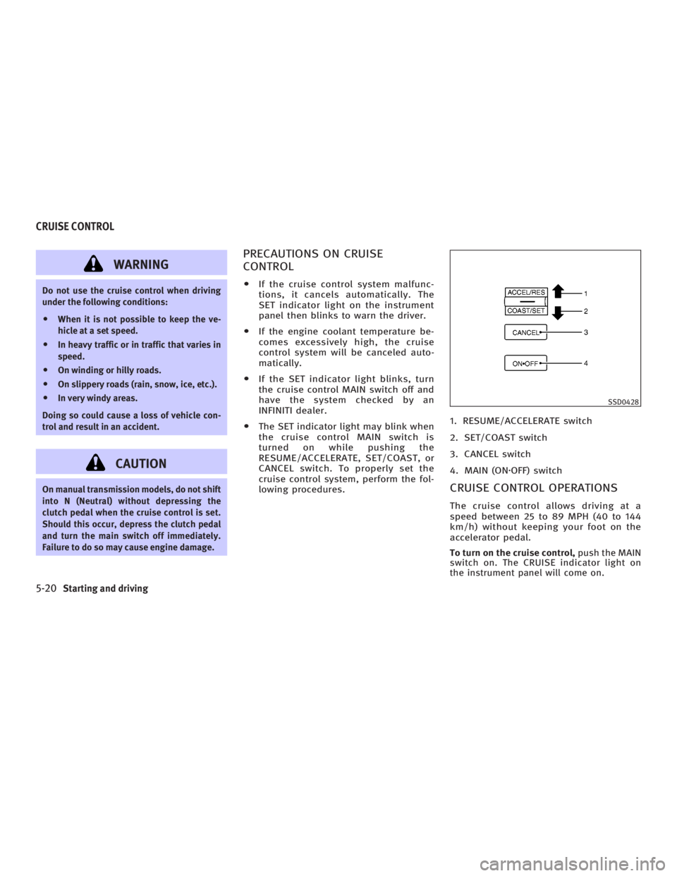
lowing procedures. 1. RESUME/ACCELERATE switch
2. SET/COAST switch
3. CANCEL switch
4. MAIN (ON z OFF) switch
CRUISE CONTROL OPERATIONS The cruise control allows driving at a
speed between 25 to 89 MPH (40 to 144
km/h) without keeping your foot on the
accelerator pedal.
To turn on the cruise control, push the MAIN
switch on. The CRUISE indicator light on
the instrument panel will come on. SSD0428
CRUISE CONTROL
5-20 Starting and driving
w 06.1.4/V35-D/V5.0
X
Page 234 of 344
WARNINGThe RAS system, although a sophisticated
device, cannot prevent accidents resulting
from careless or dangerous driving tech-
niques. Ultimately the responsibility for
safety of self and others rests in the hands of
the driver. Therefore only through attentive
and careful driving methods can the RAS
system be fully appreciated and safety as-
sured. FREEING A FROZEN DOOR LOCK To prevent a door lock from freezing, apply
de-icer or glycerin to it through the key
hole. If the lock becomes frozen, heat the
key before inserting it into the key hole.
ANTI-FREEZE In the winter when it is anticipated that the
temperature will drop below 32ÉF (0ÉC),
check antifreeze to assure proper winter
protection. For additional information, see
ªEngine cooling systemº in the ª8. Mainte-
nance and do-it-yourselfº section.
BATTERY If the battery is not fully charged during
extremely cold weather conditions, the
battery fluid may freeze and damage the
battery. To maintain maximum efficiency,
the battery should be checked regularly.
For additional information, see ªBatteryº
in the ª8. Maintenance and do-it-yourselfº
section.
DRAINING OF COOLANT WATER If the vehicle is to be left outside without
antifreeze, drain the cooling system by
opening the drain plug located under the
radiator. Refill before operating the ve-
hicle. See ªEngine cooling systemº in the ª8. Maintenance and do-it-yourselfº sec-
tion for changing engine coolant.
TIRE EQUIPMENT 1. SUMMER tires are of a tread design to
provide superior performance on dry
pavement. However, the performance
of these tires will be substantially re-
duced in snowy and icy conditions. If
you operate your vehicle on snowy or
icy roads, INFINITI recommends the
use of MUD & SNOW or ALL SEASON
tires on all four wheels. Please consult
an INFINITI dealer for the tire type,
size, speed rating and availability in-
formation.
2. For additional traction on icy roads,
studded tires may be used. However,
some provinces and states prohibit
their use. Check local, state and pro-
vincial laws before installing studded
tires.
Skid and traction capabilities of
studded snow tires, on wet or dry sur-
faces, may be poorer than that of non-
studded snow tires.
3. Tire chains may be used if desired.
Make sure they are of proper size for
the tires on your vehicle and are in-COLD WEATHER DRIVING
5-30 Starting and driving
w 06.1.4/V35-D/V5.0
X
Page 247 of 344
WARNINGO Do not continue to drive if your vehicle
overheats. Doing so could cause engine
damage or a vehicle fire.
O To avoid the danger of being scalded,
never remove the radiator cap while the
engine is still hot. When the radiator cap
is removed, pressurized hot water will
spurt out, possibly causing serious in-
jury.
O Do not open the hood if steam is coming
out.
If your vehicle is overheating (indicated
by an extremely high temperature gauge
reading), or if you feel a lack of engine
power, detect abnormal noise, etc., take
the following steps:
1. Move the vehicle safely off the road,
apply the parking brake and move the
shift lever to the N (Neutral) position
(automatic transmission to the P
(Park) position).
Do not stop the engine. 2. Turn off the air conditioner. Open all
the windows, and move the tempera-
ture control to maximum hot and the
fan control to high speed.
3. If engine overheating is caused by
climbing a long hill on a hot day, run
the engine at a fast idle (approximately
1,500 rpm) until the temperature gauge
indication returns to normal.
4. Get out of the vehicle. Look and listen
for steam or coolant escaping from the
radiator before opening the hood. (If
steam or coolant is escaping, turn off
the engine.) Do not open the hood fur-
ther until no steam or coolant can be
seen.
5. Open the engine hood.
WARNING If steam or water is coming from the engine,
stand clear to prevent getting burned.
6. Visually check if the cooling fan is run-
ning. The radiator hoses and radiator
should not leak water. If coolant is
leaking or the cooling fan does not
run, stop the engine. WARNING O Be careful not to allow your hands, hair,
jewelry or clothing to come into contact
with, or to get caught in, the engine
belts or the engine cooling fan.
O The engine cooling fan can start at any
time when the coolant temperature is
high.
7. After the engine cools down, check
the coolant level in the reservoir tank
with the engine running. Add coolant
to the reservoir tank if necessary.
Have your vehicle repaired at an
INFINITI dealer.
If needed, Roadside Assistance is avail-
able. Please see your Warranty Information
Booklet or Roadside Assistance I.D. Card
for the toll-free number to call (U.S.) or War-
ranty Information Booklet (Canada).IF YOUR VEHICLE OVERHEATS
In case of emergency
6-11
w 06.1.4/V35-D/V5.0
X
Page 266 of 344
The engine cooling system is filled at the
factory with a high-quality, year-round,
anti-freeze coolant solution. The anti-
freeze solution contains rust and corro-
sion inhibitors, therefore additional
cooling system additives are not neces-
sary.
WARNINGO Never remove the radiator or coolant res-
ervoir cap when the engine is hot. Wait
until the engine and radiator cool down.
Serious burns could be caused by high
pressure fluid escaping from the ra-
diator. See precautions in ªIf your ve-
hicle overheatsº found in the ª6. In case
of emergencyº section.
O The radiator is equipped with a pressure
type radiator cap. To prevent engine
damage, use only a genuine NISSAN ra-
diator cap. CAUTION When adding or replacing coolant, be sure to
use only a Genuine Nissan Long Life
Antifreeze/Coolant or equivalent with the
proper mixture ratio of 50% antifreeze and
50% demineralized water/distilled water.
The use of other types of engine coolant may
damage your engine cooling system. Outside temperature
down to
Antifreeze Deminer-
alized
water/
distilled
waterÉC ÉF
þ35 þ30 50% 50%
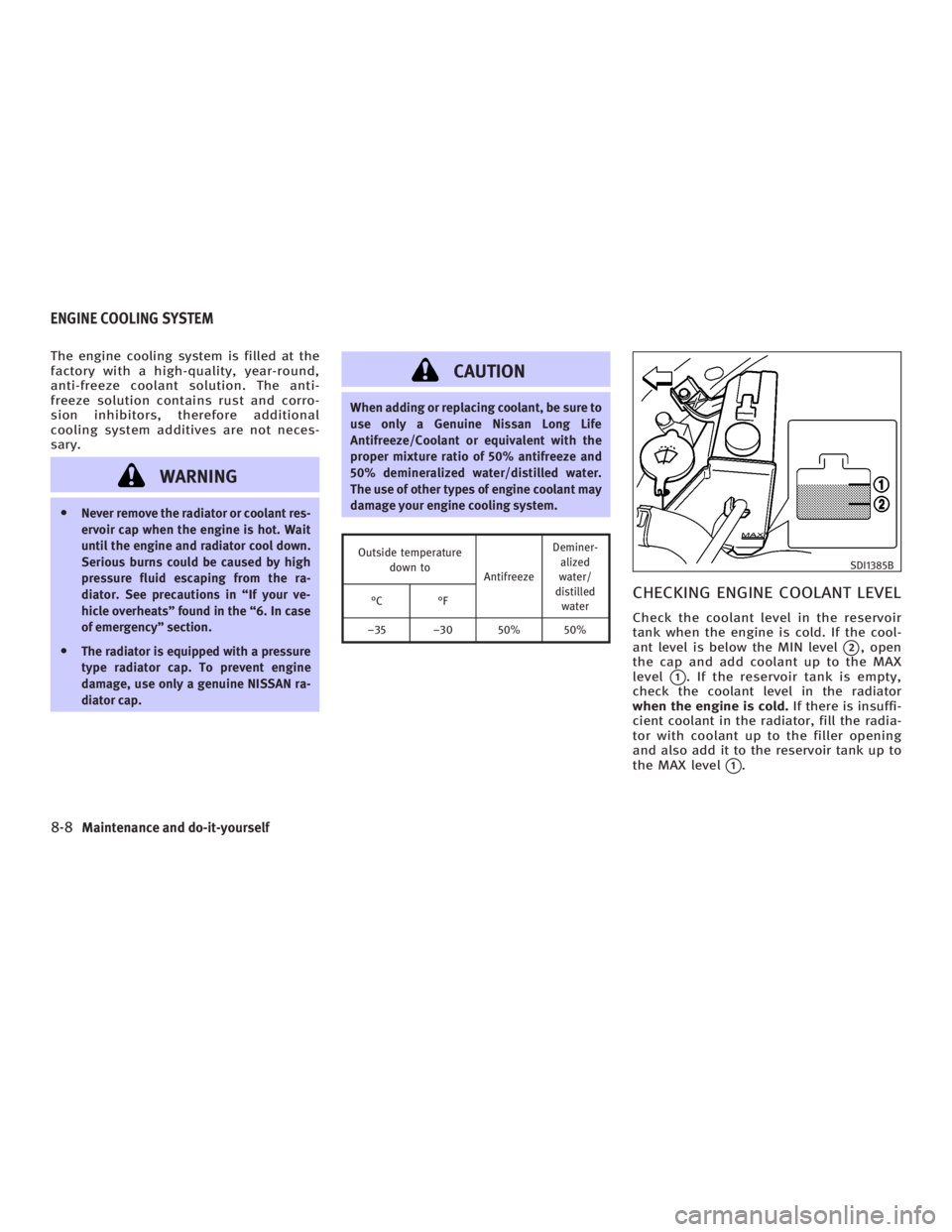
CHECKING ENGINE COOLANT LEVEL Check the coolant level in the reservoir
tank when the engine is cold. If the cool-
ant level is below the MIN level
q 2
, open
the cap and add coolant up to the MAX
level
q 1
. If the reservoir tank is empty,
check the coolant level in the radiator
when the engine is cold. If there is insuffi-
cient coolant in the radiator, fill the radia-
tor with coolant up to the filler opening
and also add it to the reservoir tank up to
the MAX level
q 1
. SDI1385B
ENGINE COOLING SYSTEM
8-8 Maintenance and do-it-yourself
w 06.1.4/V35-D/V5.0
X