engine coolant INFINITI M 2010 Owners Manual
[x] Cancel search | Manufacturer: INFINITI, Model Year: 2010, Model line: M, Model: INFINITI M 2010Pages: 445, PDF Size: 6.15 MB
Page 17 of 445
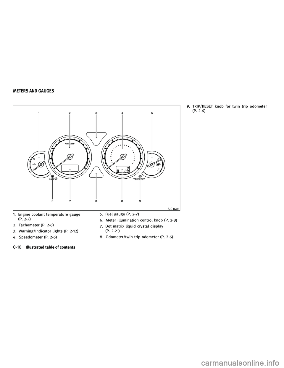
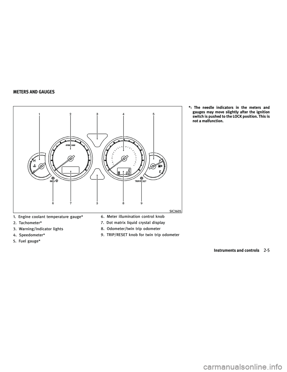
1. Engine coolant temperature gauge(P. 2-7)
2. Tachometer (P. 2-6)
3. Warning/Indicator lights (P. 2-12)
4. Speedometer (P. 2-6) 5. Fuel gauge (P. 2-7)
6. Meter illumination control knob (P. 2-8)
7. Dot matrix liquid crystal display
(P. 2-21)
8. Odometer/twin trip odometer (P. 2-6) 9. TRIP/RESET knob for twin trip odometer
(P. 2-6)
SIC3605
METERS AND GAUGES
0-10Illustrated table of contents
wÐ
Ð
05/19/09Ðtbrooks
X
Page 18 of 445
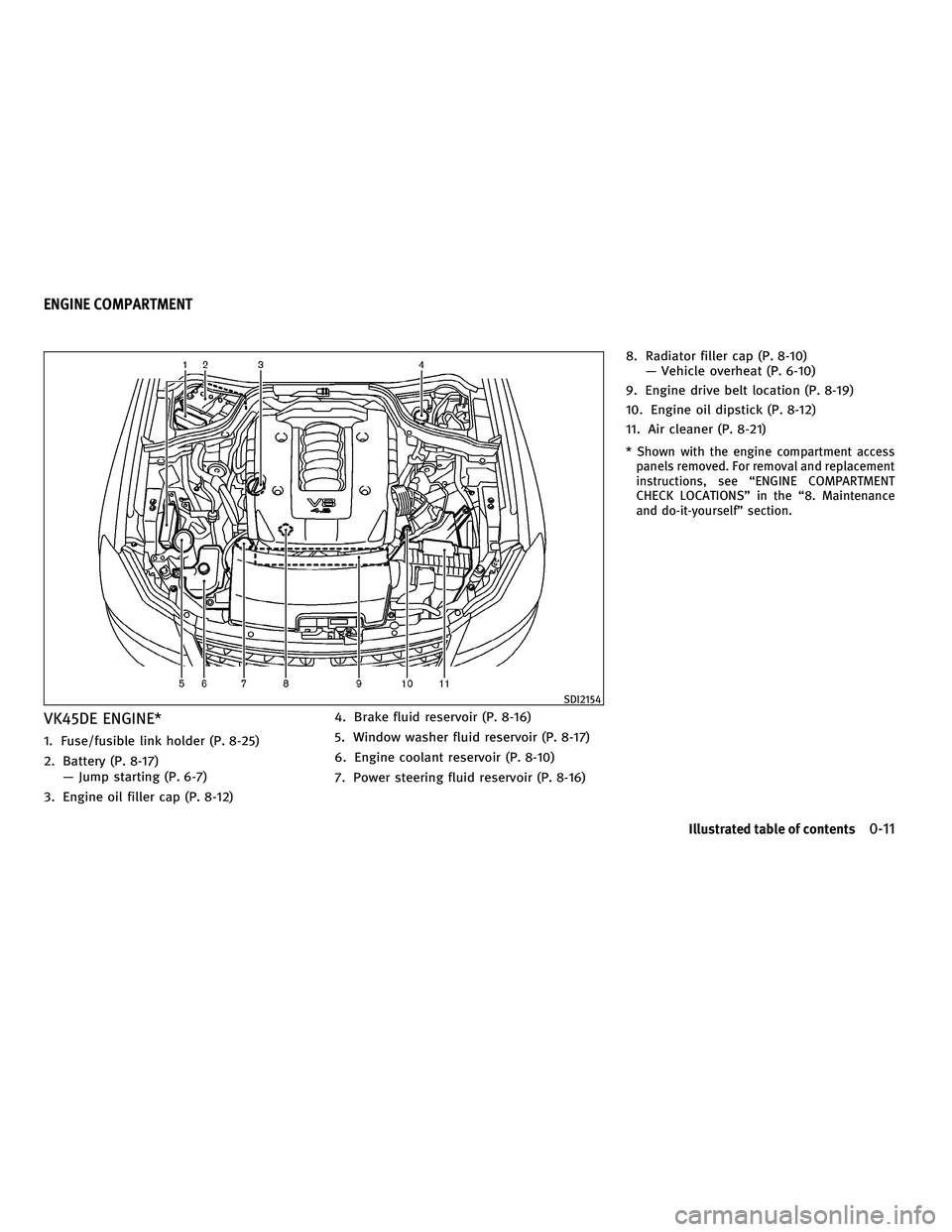
VK45DE ENGINE*
1. Fuse/fusible link holder (P. 8-25)
2. Battery (P. 8-17)Ð Jump starting (P. 6-7)
3. Engine oil filler cap (P. 8-12) 4. Brake fluid reservoir (P. 8-16)
5. Window washer fluid reservoir (P. 8-17)
6. Engine coolant reservoir (P. 8-10)
7. Power steering fluid reservoir (P. 8-16)8. Radiator filler cap (P. 8-10)
Ð Vehicle overheat (P. 6-10)
9. Engine drive belt location (P. 8-19)
10. Engine oil dipstick (P. 8-12)
11. Air cleaner (P. 8-21)
* Shown with the engine compartment access panels removed. For removal and replacement
instructions, see ªENGINE COMPARTMENT
CHECK LOCATIONSº in the ª8. Maintenance
and do-it-yourselfº section.
SDI2154
ENGINE COMPARTMENT
Illustrated table of contents0-11
wÐ
Ð
05/14/09Ðpattie
X
Page 19 of 445
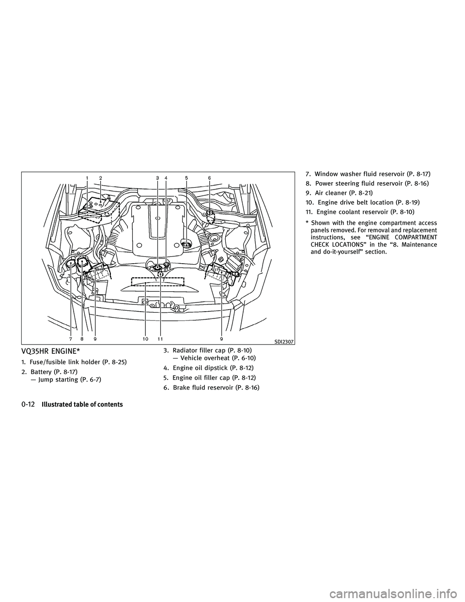
VQ35HR ENGINE*
1. Fuse/fusible link holder (P. 8-25)
2. Battery (P. 8-17)Ð Jump starting (P. 6-7) 3. Radiator filler cap (P. 8-10)
Ð Vehicle overheat (P. 6-10)
4. Engine oil dipstick (P. 8-12)
5. Engine oil filler cap (P. 8-12)
6. Brake fluid reservoir (P. 8-16) 7. Window washer fluid reservoir (P. 8-17)
8. Power steering fluid reservoir (P. 8-16)
9. Air cleaner (P. 8-21)
10. Engine drive belt location (P. 8-19)
11. Engine coolant reservoir (P. 8-10)
* Shown with the engine compartment access
panels removed. For removal and replacement
instructions, see ªENGINE COMPARTMENT
CHECK LOCATIONSº in the ª8. Maintenance
and do-it-yourselfº section.
SDI2307
0-12Illustrated table of contents
wÐ
Ð
05/14/09Ðpattie
X
Page 77 of 445
2 Instruments and controls
Cockpit........................................... 2-2
Instrument panel .................................. 2-3
Meters and gauges ................................ 2-5
Speedometer and odometer ..................... 2-6
Tachometer .................................... 2-6
Engine coolant temperature gauge ............... 2-7
Fuel gauge ..................................... 2-7
Meter/ring illumination and needle sweep ........ 2-8
Compass (if so equipped) .......................... 2-9
Zone variation change procedure ...............2-10
Warning/indicator lights and audible reminders .....2-12
Checking bulbs ............................... 2-13
Warning lights ................................ 2-13
Indicator lights ................................ 2-18
Audible reminders ............................. 2-20
Dot matrix liquid crystal display ...................2-21
Indicators for operation ........................ 2-22
Security systems ................................. 2-24
Vehicle security system ........................ 2-24
INFINITI Vehicle Immobilizer System ............2-25
Windshield wiper and washer switch ...............2-27
Rain-sensing auto wiper system ................2-28
Rear window and outside mirror defroster switch . . . 2-28 Headlight and turn signal switch
..................2-29
Xenon headlights ............................. 2-29
Headlight switch .............................. 2-29
Turn signal switch ............................. 2-33
Fog light switch ............................... 2-33
Hazard warning flasher switch .....................2-33
Horn ............................................ 2-34
Heated seats (rear seats) (if so equipped) ..........2-34
Climate controlled seats (front seats) ..............2-35
Lane Departure Warning (LDW) switch
(if so equipped) .................................. 2-36
SNOW mode switch (if so equipped) ...............2-37
Vehicle Dynamic Control (VDC) OFF switch ..........2-37
Clock ............................................ 2-38
Adjusting the time ............................. 2-38
Power outlets .................................... 2-38
Cigarette lighter and ashtrays .....................2-39
Front ......................................... 2-39
Rear ......................................... 2-39
Storage ......................................... 2-40
Cup holders .................................. 2-40
Sunglasses holder ............................. 2-41
Glove box .................................... 2-41
wÐ
Ð
05/19/09Ðtbrooks
X
Page 82 of 445
1. Engine coolant temperature gauge*
2. Tachometer*
3. Warning/Indicator lights
4. Speedometer*
5. Fuel gauge*6. Meter illumination control knob
7. Dot matrix liquid crystal display
8. Odometer/twin trip odometer
9. TRIP/RESET knob for twin trip odometer
*: The needle indicators in the meters and
gauges may move slightly after the ignition
switch is pushed to the LOCK position. This is
not a malfunction.
SIC3605
METERS AND GAUGES
Instruments and controls2-5
wÐ
Ð
05/19/09Ðtbrooks
X
Page 84 of 445
ENGINE COOLANT TEMPERATURE
GAUGE
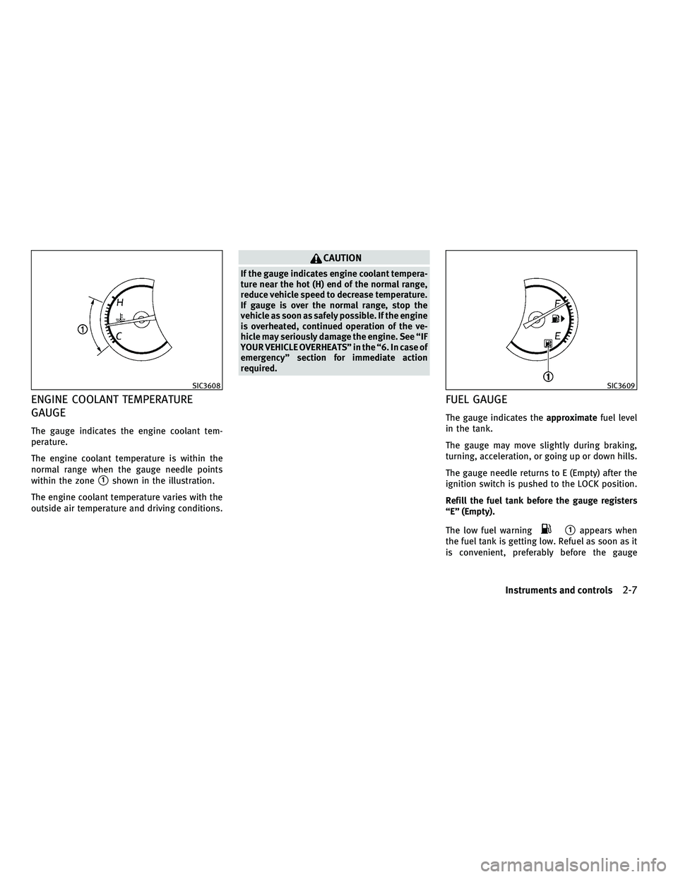
The gauge indicates the engine coolant tem-
perature.
The engine coolant temperature is within the
normal range when the gauge needle points
within the zone
s1shown in the illustration.
The engine coolant temperature varies with the
outside air temperature and driving conditions.
CAUTION
If the gauge indicates engine coolant tempera-
ture near the hot (H) end of the normal range,
reduce vehicle speed to decrease temperature.
If gauge is over the normal range, stop the
vehicle as soon as safely possible. If the engine
is overheated, continued operation of the ve-
hicle may seriously damage the engine. See ªIF
YOUR VEHICLE OVERHEATSº in the ª6. In case of
emergencyº section for immediate action
required.
FUEL GAUGE
The gauge indicates the approximatefuel level
in the tank.
The gauge may move slightly during braking,
turning, acceleration, or going up or down hills.
The gauge needle returns to E (Empty) after the
ignition switch is pushed to the LOCK position.
Refill the fuel tank before the gauge registers
ªEº (Empty).
The low fuel warning
s1appears when
the fuel tank is getting low. Refuel as soon as it
is convenient, preferably before the gauge
SIC3608SIC3609
Instruments and controls2-7
wÐ
Ð
05/14/09Ðpattie
X
Page 196 of 445
REAR SWITCHES FOR CLIMATE
CONTROL (if so equipped)
The rear seat passengers can adjust the climate
control system using the climate controls in the
rear armrest panel.
ªAUTOº button: automatic climate control
mode on
ª
º button: Fan speed control up (Max fan
speed !return to Low fan speed)
ª
º button: Temperature control up/down
OPERATING TIPS
When the engine coolant temperature and out-
side air temperature are low, the air flow from
the foot outlets may not operate for a maximum
of 150 seconds. This is not a malfunction. After
the coolant temperature warms up, air will flow
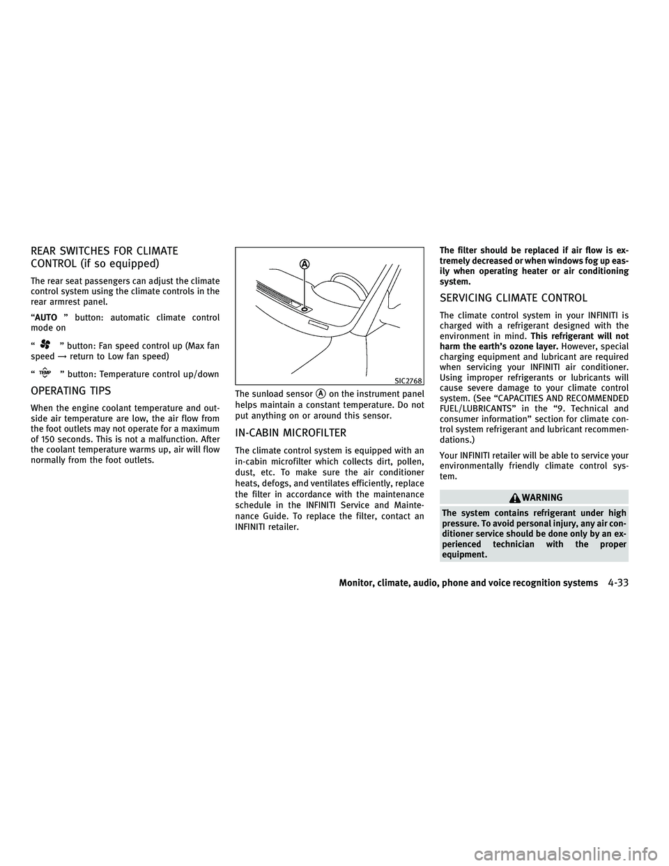
normally from the foot outlets. The sunload sensor
sAon the instrument panel
helps maintain a constant temperature. Do not
put anything on or around this sensor.
IN-CABIN MICROFILTER
The climate control system is equipped with an
in-cabin microfilter which collects dirt, pollen,
dust, etc. To make sure the air conditioner
heats, defogs, and ventilates efficiently, replace
the filter in accordance with the maintenance
schedule in the INFINITI Service and Mainte-
nance Guide. To replace the filter, contact an
INFINITI retailer. The filter should be replaced if air flow is ex-
tremely decreased or when windows fog up eas-
ily when operating heater or air conditioning
system.
SERVICING CLIMATE CONTROL
The climate control system in your INFINITI is
charged with a refrigerant designed with the
environment in mind.
This refrigerant will not
harm the earth's ozone layer. However, special
charging equipment and lubricant are required
when servicing your INFINITI air conditioner.
Using improper refrigerants or lubricants will
cause severe damage to your climate control
system. (See ªCAPACITIES AND RECOMMENDED
FUEL/LUBRICANTSº in the ª9. Technical and
consumer informationº section for climate con-
trol system refrigerant and lubricant recommen-
dations.)
Your INFINITI retailer will be able to service your
environmentally friendly climate control sys-
tem.
WARNING
The system contains refrigerant under high
pressure. To avoid personal injury, any air con-
ditioner service should be done only by an ex-
perienced technician with the proper
equipment.
SIC2768
Monitor, climate, audio, phone and voice recognition systems4-33
wÐ
Ð
05/14/09Ðpattie
X
Page 286 of 445
Brake system.................................... 5-49
Braking precautions ........................... 5-49
Parking brake break-in ......................... 5-50
Brake assist ..................................... 5-50
Brake assist .................................. 5-50
Preview function (for Intelligent Cruise
Control (ICC) system equipped models) ..........5-50
Anti-lock Braking System (ABS) .................5-53
Vehicle Dynamic Control (VDC) system .............5-54
Rear active steer system (if so equipped) ...........5-55Cold weather driving
............................. 5-56
Freeing a frozen door lock .....................5-56
Anti-freeze .................................... 5-56
Battery ....................................... 5-56
Draining of coolant water ......................5-56
Tire equipment ................................ 5-56
Special winter equipment ......................5-56
Driving on snow or ice ......................... 5-56
Engine block heater (if so equipped) ............5-57
wÐ
Ð
05/15/09Ðpattie
X
Page 308 of 445
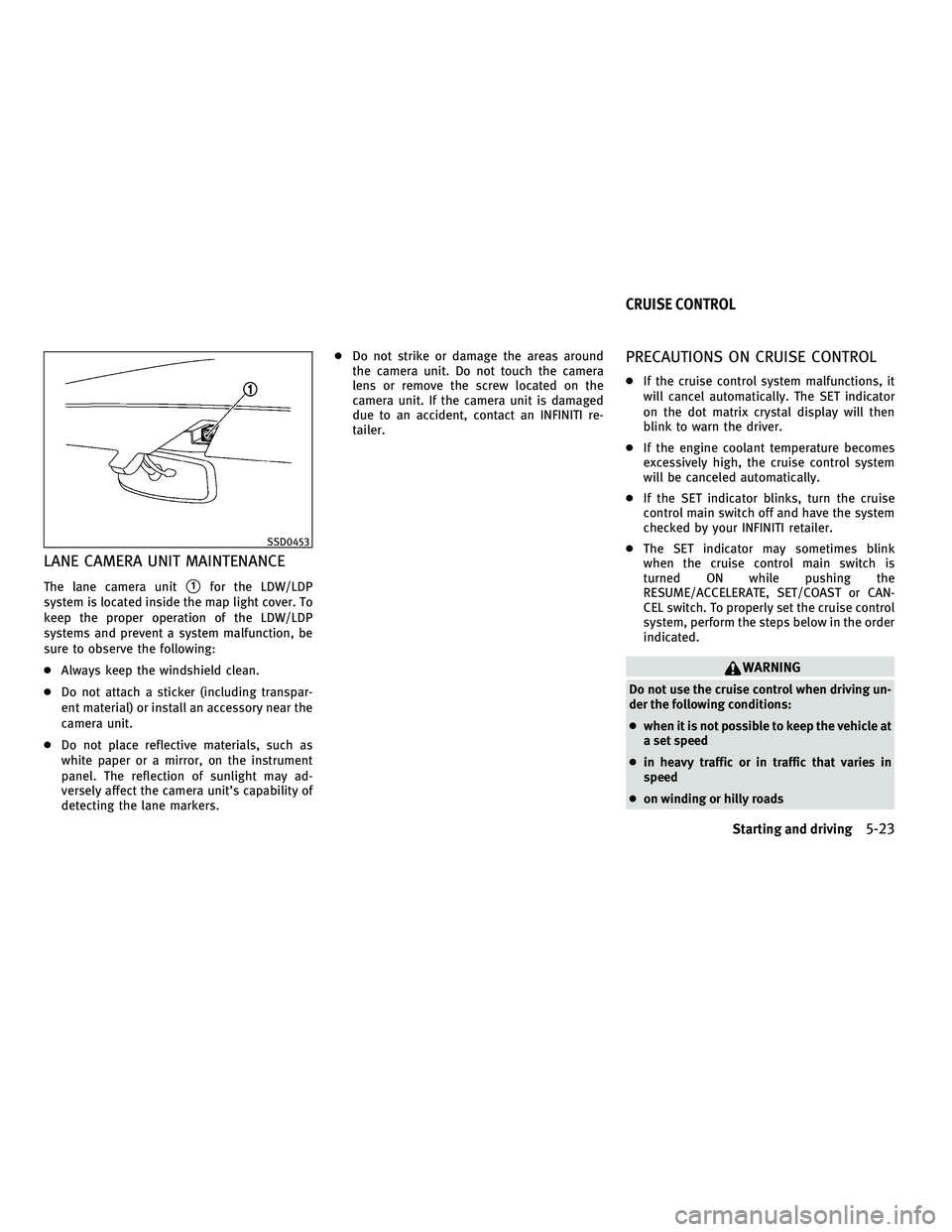
LANE CAMERA UNIT MAINTENANCE
The lane camera units1for the LDW/LDP
system is located inside the map light cover. To
keep the proper operation of the LDW/LDP
systems and prevent a system malfunction, be
sure to observe the following:
c Always keep the windshield clean.
c Do not attach a sticker (including transpar-
ent material) or install an accessory near the
camera unit.
c Do not place reflective materials, such as
white paper or a mirror, on the instrument
panel. The reflection of sunlight may ad-
versely affect the camera unit's capability of
detecting the lane markers. c
Do not strike or damage the areas around
the camera unit. Do not touch the camera
lens or remove the screw located on the
camera unit. If the camera unit is damaged
due to an accident, contact an INFINITI re-
tailer.
PRECAUTIONS ON CRUISE CONTROL
cIf the cruise control system malfunctions, it
will cancel automatically. The SET indicator
on the dot matrix crystal display will then
blink to warn the driver.
c If the engine coolant temperature becomes
excessively high, the cruise control system
will be canceled automatically.
c If the SET indicator blinks, turn the cruise
control main switch off and have the system
checked by your INFINITI retailer.
c The SET indicator may sometimes blink
when the cruise control main switch is
turned ON while pushing the
RESUME/ACCELERATE, SET/COAST or CAN-
CEL switch. To properly set the cruise control
system, perform the steps below in the order
indicated.
WARNING
Do not use the cruise control when driving un-
der the following conditions:
cwhen it is not possible to keep the vehicle at
a set speed
c in heavy traffic or in traffic that varies in
speed
c on winding or hilly roads
SSD0453
CRUISE CONTROL
Starting and driving5-23
wÐ
Ð
05/15/09Ðpattie
X
Page 325 of 445
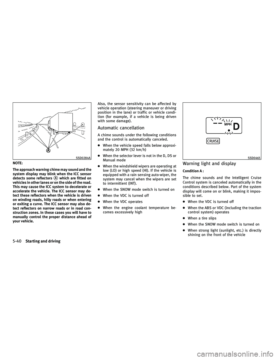
NOTE:
The approach warning chime may sound and the
system display may blink when the ICC sensor
detects some reflectors
sAwhich are fitted on
vehicles in other lanes or on the side of the road.
This may cause the ICC system to decelerate or
accelerate the vehicle. The ICC sensor may de-
tect these reflectors when the vehicle is driven
on winding roads, hilly roads or when entering
or exiting a curve. The ICC sensor may also de-
tect reflectors on narrow roads or in road con-
struction zones. In these cases you will have to
manually control the proper distance ahead of
your vehicle. Also, the sensor sensitivity can be affected by
vehicle operation (steering maneuver or driving
position in the lane) or traffic or vehicle condi-
tion (for example, if a vehicle is being driven
with some damage).
Automatic cancellation
A chime sounds under the following conditions
and the control is automatically canceled.
c
When the vehicle speed falls below approxi-
mately 20 MPH (32 km/h)
c When the selector lever is not in the D, DS or
Manual mode
c When the windshield wipers are operating at
low (LO) or high speed (HI). If the vehicle is
equipped with a rain sensing auto-wiper, the
system may cancel when the wipers are set
to intermittent (INT).
c When the SNOW mode switch is turned on
c When the VDC is turned off
c When the VDC operates
c When the engine coolant temperature be-
comes excessively high
Warning light and display
Condition A :
The chime sounds and the Intelligent Cruise
Control system is canceled automatically in the
conditions described below. Part of the system
display will come on or blink, making it impos-
sible to set.
cWhen the VDC is turned off
c When the ABS or VDC (including the traction
control system) operates
c When a tire slips
c When the SNOW mode switch is turned on
c When strong light (sunlight, etc.) is directly
shining on the front of the vehicle
SSD0284ASSD0465
5-40Starting and driving
wÐ
Ð
05/19/09Ðtbrooks
X