fuse INFINITI M 2010 Owners Manual
[x] Cancel search | Manufacturer: INFINITI, Model Year: 2010, Model line: M, Model: INFINITI M 2010Pages: 445, PDF Size: 6.15 MB
Page 15 of 445

1. Side ventilator (P. 4-28)
2. Meters and gauges (P. 2-5)
3. Center ventilator (P. 4-28)
4. Security indicator light (P. 2-26)
5. Hazard warning flasher switch (P. 2-33)6. Automatic climate control system
(P. 4-29) 7. Center multi-function control panel
(P. 4-2)
Ð Navigation system* (if so equipped)
Ð Vehicle information and setting buttons
(P. 4-7)
Ð Phone system (P. 4-74, P. 4-84)
Ð Audio system (P. 4-34)
8. Front passenger supplemental air bag (P. 1-40)
9. Fuse box cover (P. 8-25)
10. Parking brake Ð Operation (P. 5-16)
Ð Parking (P. 5-48)
11. Push-button ignition switch (P. 5-8)
12. Clock (P. 2-38)
13. Climate controlled seat switch (if so equipped) (P. 2-35)
14. Snow mode switch (if so equipped) (P. 2-37)
15. Rear sunshade switch (if so equipped) (P. 2-47)
16. Rear control cancel switch (if so equipped) (P. 2-47) or Climate controlled
seat switch (if so equipped)
(P. 2-35)
17. Climate controlled seat switch (if so equipped) (P. 2-35)
18. Cigarette lighter and ashtrays (P. 2-39)
SIC3551
INSTRUMENT PANEL
0-8Illustrated table of contents
wÐ
Ð
05/19/09Ðtbrooks
X
Page 18 of 445
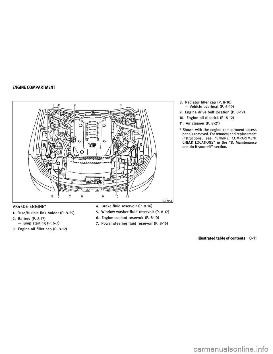
VK45DE ENGINE*
1. Fuse/fusible link holder (P. 8-25)
2. Battery (P. 8-17)Ð Jump starting (P. 6-7)
3. Engine oil filler cap (P. 8-12) 4. Brake fluid reservoir (P. 8-16)
5. Window washer fluid reservoir (P. 8-17)
6. Engine coolant reservoir (P. 8-10)
7. Power steering fluid reservoir (P. 8-16)8. Radiator filler cap (P. 8-10)
Ð Vehicle overheat (P. 6-10)
9. Engine drive belt location (P. 8-19)
10. Engine oil dipstick (P. 8-12)
11. Air cleaner (P. 8-21)
* Shown with the engine compartment access panels removed. For removal and replacement
instructions, see ªENGINE COMPARTMENT
CHECK LOCATIONSº in the ª8. Maintenance
and do-it-yourselfº section.
SDI2154
ENGINE COMPARTMENT
Illustrated table of contents0-11
wÐ
Ð
05/14/09Ðpattie
X
Page 19 of 445
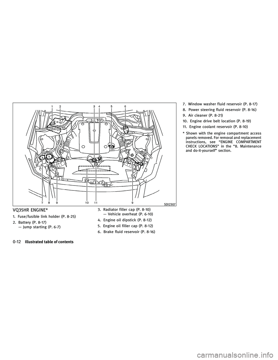
VQ35HR ENGINE*
1. Fuse/fusible link holder (P. 8-25)
2. Battery (P. 8-17)Ð Jump starting (P. 6-7) 3. Radiator filler cap (P. 8-10)
Ð Vehicle overheat (P. 6-10)
4. Engine oil dipstick (P. 8-12)
5. Engine oil filler cap (P. 8-12)
6. Brake fluid reservoir (P. 8-16) 7. Window washer fluid reservoir (P. 8-17)
8. Power steering fluid reservoir (P. 8-16)
9. Air cleaner (P. 8-21)
10. Engine drive belt location (P. 8-19)
11. Engine coolant reservoir (P. 8-10)
* Shown with the engine compartment access
panels removed. For removal and replacement
instructions, see ªENGINE COMPARTMENT
CHECK LOCATIONSº in the ª8. Maintenance
and do-it-yourselfº section.
SDI2307
0-12Illustrated table of contents
wÐ
Ð
05/14/09Ðpattie
X
Page 80 of 445

1. Side ventilator (P. 4-28)
2. Meters and gauges (P. 2-5)
3. Center ventilator (P. 4-28)
4. Security indicator light (P. 2-26)
5. Hazard warning flasher switch (P. 2-33)6. Automatic climate control system
(P. 4-29)
7. Center multi-function control panel Ð Navigation system* (if so equipped) Ð Vehicle information and setting buttons
(P. 4-7) Ð Phone system (P. 4-74, P. 4-84)
Ð Audio system (P. 4-34)
8. Front passenger supplemental air bag (P. 1-40)
9. Fuse box cover (P. 8-25)
10. Parking brake Ð Operation (P. 5-16)
Ð Parking (P. 5-48)
11. Push-button ignition switch (P. 5-8)
12. Clock (P. 2-38)
13. Climate controlled seat switch (if so equipped) (P. 2-35)
14. Snow mode switch (if so equipped) (P. 2-37)
15. Rear sunshade switch (if so equipped) (P. 2-47)
16. Rear control cancel switch (if so equipped) (P. 2-47) or Climate controlled
seat switch (if so equipped)
(P. 2-35)
17. Climate controlled seat switch (if so equipped) (P. 2-35)
18. Cigarette lighter and ashtrays (P. 2-39)
19. CompactFlash card slot (if so equipped) (P. 4-34)
SIC3551
INSTRUMENT PANEL
Instruments and controls2-3
wÐ
Ð
05/19/09Ðtbrooks
X
Page 115 of 445

If the power supply is disconnected, the clock
will not indicate the correct time. Readjust the
time.
ADJUSTING THE TIME
1. To set the clock forward, push the button
s1.
2. To set the clock backward, push the but- ton
s2.
3. To move forward or backward faster, push and hold the button more than 5 seconds.
For details about display clock adjustment (if so
equipped), see ªHOW TO USE SETTING BUTTONº
in the ª4. Monitor, climate, audio, phone and
voice recognition systemsº section. The power outlets are located on the back side
and inside (if equipped) of the center console
for powering electrical accessories such as a
cellular telephone.
CAUTION
c
The outlet and plug may be hot during or
immediately after use.
c Do not use with accessories that exceed a 12
volt, 120W (10A) power draw. Do not use
double adapters or more than one electrical
accessory.
c Use power outlet with the engine running to
avoid discharging the vehicle battery.
c Avoid using power outlet when the air condi-
tioner, headlights or rear window defroster
is on.
c This power outlet is not designed for use
with a cigarette lighter unit.
c Push the plug in as far as it will go. If good
contact is not made, the plug may overheat
or the internal temperature fuse may open.
c Before inserting or disconnecting a plug, be
sure the electrical accessory being used is
turned OFF.
c When not in use, be sure to close the cap. Do
not allow water to contact the outlet.
SIC2772SIC2773
Only for model without DVD player
SIC2774
CLOCK POWER OUTLETS
2-38Instruments and controls
wÐ
Ð
05/14/09Ðpattie
X
Page 157 of 445

The automatic drive positioner system has the
following features:
cEntry/exit function
c Memory storage
ENTRY/EXIT FUNCTION
This system is designed so that the driver's seat
and steering column will automatically move
when the selector lever is in the P (Park)
position. This allows the driver to get into and
out of the driver's seat more easily.
The driver's seat will slide backward and the
steering wheel will move up when the driver's
door is opened with the ignition switch in the
LOCK position.
The driver's seat and steering wheel will return
to the previous positions when one of the
following is operated:
cWhen the ignition switch is pushed to the
ACC position after the driver's door is
closed.
c When the ignition switch is pushed to the
ON position.
c When the Intelligent Key is inserted into the
port after the driver's door is closed. The driver's seat will not return to the previous
positions if the seat or steering adjusting
switch is operated when the seat is at the exit
position.
Cancel or activate entry/exit function
To cancel or activate the entry/exit function, the
selector lever must be in the P (Park) position
with the ignition switch in the LOCK position.
Push and hold the SET switch for more than 10
seconds to cancel or activate the entry/exit
function.
The indicator lights on the memory switches (1
and 2) will blink once when the function is
canceled, and the indicator lights will blink
twice when the function is activated.
The entry/exit function can also be canceled or
activated if the ªLift Steering Wheel on Exitº key
or ªSlide Driver Seat Back on Exitº key is turned
to ON or OFF in the ªComfort & Conv.º settings.
(See ªVEHICLE INFORMATION AND SETTINGSº in
the ª4. Monitor, climate, audio, phone and
voice recognition systemsº section.)
Initialize entry/exit function
If the battery cable is disconnected, or if the
fuse opens, the entry/exit function will not work
though this function was set on before. In such
a case, after connecting the battery or replacing
with a new fuse, open and close the driver's
door more than two times after the ignition
switch is pushed to the ON position once, then
pushed to the LOCK position. The entry/exit
function will be activated.
AUTOMATIC DRIVE POSITIONER
3-26Pre-driving checks and adjustments
wÐ
Ð
05/14/09Ðpattie
X
Page 159 of 445
position, the outside mirror will move with
the initial tilt-down angle, if the reverse
tilt-down position is stored.
Linking Intelligent Key to a stored
memory position
The Intelligent Key can be linked to a stored
memory position with the following procedure.
1. Follow the steps for storing a memoryposition.
2. While the indicator light for the memory switch being set is illuminated for 5 sec-
onds, push the
button on the Intel-
ligent Key. If the indicator light blinks, the
Intelligent Key is linked to that memory
setting.
Push the ignition switch to the LOCK position,
and push the
button on the Intelligent
Key. The driver's seat, steering wheel and out-
side mirrors will move to the memorized posi-
tion.
Confirming memory storage
c Push the ignition switch to the ON position
and push the SET switch. If the main memory
has not been stored, the indicator light will
come on for approximately 0.5 second.
When the memory has stored in position, the
indicator light will stay on for approximately
5 seconds.
c If the battery cable is disconnected, or if the
fuse opens, the memory will be canceled. In
this case, reset the desired position using
the previous procedure.
c If optional Intelligent Keys are added to your
vehicle, perform the memory storage proce-
dure to switch (1 or 2) and linking Intelligent
Key procedure to a stored memory position
again for each Intelligent Key. For additional
Intelligent Key information, see ªKEYSº ear-
lier in this section.
Selecting the memorized position
1. Move the selector lever to the P (Park)
position.
2. Use one of the following methods to move the driver's seat, steering column and
outside mirrors.
cPush the ignition switch to the ON posi-
tion and push the memory switch (1 or 2)
fully for at least 1 second.
c Within 45 seconds after opening the driv-
er's door, push the memory switch (1 or 2)
fully for at least 1 second.
The driver's seat, steering column and
outside mirrors will move to the memo-
rized position with the indicator light
flashing, and then the light will stay on for
approximately 5 seconds.
3-28Pre-driving checks and adjustments
wÐ
Ð
05/14/09Ðpattie
X
Page 208 of 445

SCAN tuning :
Push the SCAN tuning button to tune from low
to high frequencies and stop at each broadcast-
ing station for 5 seconds. Pushing the button
again during this 5-second period will stop
SCAN tuning and the radio will remain tuned to
that station.
If the SCAN tuning button is not pushed within
5 seconds, SCAN tuning moves to the next
station.
PRESET select :
Push the PRESET select button to go to the next
PRESET. After choosing from the PRESET A, B or
C, you can select the desired station using the
INFINITI controller or pushing the station preset
buttons
to.
toStation memory operations :
6 stations can be set for PRESET A, B and C. The
PRESET A, B and C function allows you to store
a combination of FM, AM and SAT stations for
easy access.
1. Choose preset station A, B or C using the preset select button.
2. Tune to the desired station using the SEEK, SCAN or TUNE button. 3. Select the desired station and push and
hold the desired station preset button
tountil a beep sound is
heard. (The radio mutes when the select
button is pushed.)
4. The station indicator will then come on and the sound will resume. Memorizing is
now complete.
5. Other buttons can be set in the same manner.
If the battery cable is disconnected, or if the
fuse opens, the radio memory will be erased. In
that case, reset the desired stations.
Text :
When the ªText º key is selected with the
INFINITI controller on the display and then the
ENTER button is pushed while the satellite radio
is being played, the text information will be
displayed on the screen.
c CH Name
c Category
c Name
c Title
c Other
If your vehicle is equipped with the AUDIO TEXT
ª
º button on the center multi-function control panel, push this button while the satel-
lite programming is selected to show the text
information.
Compact Disc (CD) player/changer
operation
Push the ignition switch to the ACC or ON
position, push the LOAD button (if so equipped)
and insert the Compact Disc (CD) into the slot
with the label side facing up. The CD will be
guided automatically into the slot and start
playing.
After loading the CD, the number of tracks on
the CD and the play time will appear on the
display.
If the radio is already operating, it will automati-
cally turn off and the CD will play.
If the system has been turned off while the CD
was playing, pushing the ON´OFF/VOL control
knob will start the CD.
Do not use 3.1 in (8 cm) discs.
CD LOAD (if so equipped) :
To insert a CD in the CD changer, push the LOAD
button for less than 1.5 seconds. Select the
Monitor, climate, audio, phone and voice recognition systems4-45
wÐ
Ð
05/14/09Ðpattie
X
Page 246 of 445
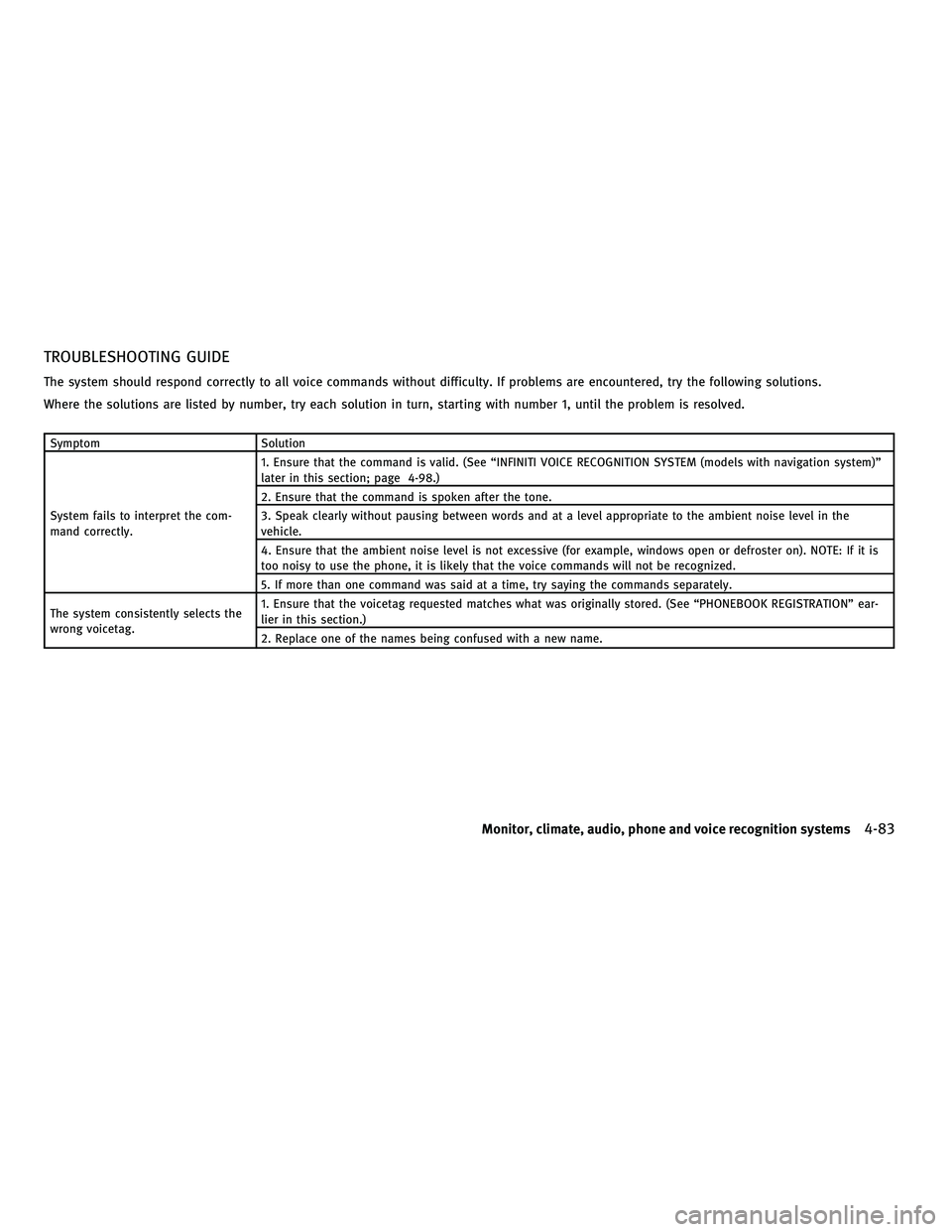
TROUBLESHOOTING GUIDE
The system should respond correctly to all voice commands without difficulty. If problems are encountered, try the following solutions.
Where the solutions are listed by number, try each solution in turn, starting with number 1, until the problem is resolved.
SymptomSolution
System fails to interpret the com-
mand correctly. 1. Ensure that the command is valid. (See ªINFINITI VOICE RECOGNITION SYSTEM (models with navigation system)º
later in this section; page 4-98.)
2. Ensure that the command is spoken after the tone.
3. Speak clearly without pausing between words and at a level appropriate to the ambient noise level in the
vehicle.
4. Ensure that the ambient noise level is not excessive (for example, windows open or defroster on). NOTE: If it is
too noisy to use the phone, it is likely that the voice commands will not be recognized.
5. If more than one command was said at a time, try saying the commands separately.
The system consistently selects the
wrong voicetag. 1. Ensure that the voicetag requested matches what was originally stored. (See ªPHONEBOOK REGISTRATIONº ear-
lier in this section.)
2. Replace one of the names being confused with a new name.
Monitor, climate, audio, phone and voice recognition systems4-83
wÐ
Ð
05/14/09Ðpattie
X
Page 260 of 445
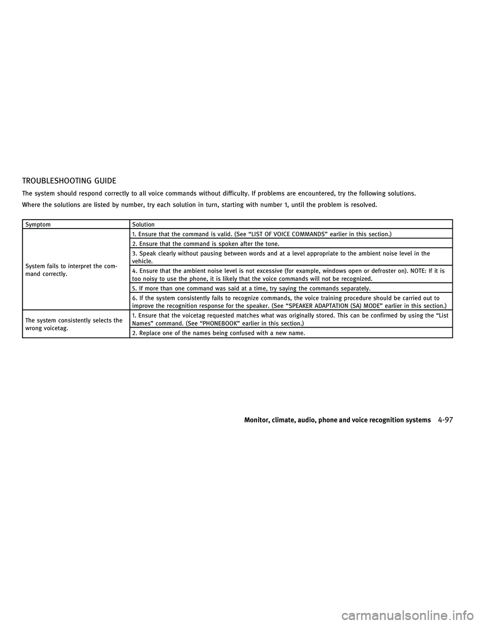
TROUBLESHOOTING GUIDE
The system should respond correctly to all voice commands without difficulty. If problems are encountered, try the following solutions.
Where the solutions are listed by number, try each solution in turn, starting with number 1, until the problem is resolved.
SymptomSolution
System fails to interpret the com-
mand correctly. 1. Ensure that the command is valid. (See ªLIST OF VOICE COMMANDSº earlier in this section.)
2. Ensure that the command is spoken after the tone.
3. Speak clearly without pausing between words and at a level appropriate to the ambient noise level in the
vehicle.
4. Ensure that the ambient noise level is not excessive (for example, windows open or defroster on). NOTE: If it is
too noisy to use the phone, it is likely that the voice commands will not be recognized.
5. If more than one command was said at a time, try saying the commands separately.
6. If the system consistently fails to recognize commands, the voice training procedure should be carried out to
improve the recognition response for the speaker. (See ªSPEAKER ADAPTATION (SA) MODEº earlier in this section.)
The system consistently selects the
wrong voicetag. 1. Ensure that the voicetag requested matches what was originally stored. This can be confirmed by using the ªList
Namesº command. (See ªPHONEBOOKº earlier in this section.)
2. Replace one of the names being confused with a new name.
Monitor, climate, audio, phone and voice recognition systems4-97
wÐ
Ð
05/14/09Ðpattie
X