clock INFINITI M-HEV 2013 Owners Manual
[x] Cancel search | Manufacturer: INFINITI, Model Year: 2013, Model line: M-HEV, Model: INFINITI M-HEV 2013Pages: 530, PDF Size: 3.71 MB
Page 29 of 530

0-8Illustrated table of contents
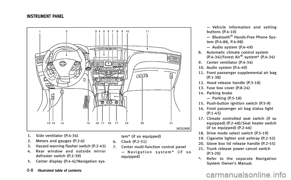
JVC0290X
1. Side ventilator (P.4-34)
2. Meters and gauges (P.2-6)
3. Hazard warning flasher switch (P.2-45)
4. Rear window and outside mirrordefroster switch (P.2-39)
5. Center display (P.4-4)/Navigation sys- tem* (if so equipped)
6. Clock (P.2-51)
7. Center multi-function control panel —Navigation system* (if so
equipped) —
Vehicle information and setting
buttons (P.4-10)
— Bluetooth
®Hands-Free Phone Sys-
tem (P.4-88, P.4-98)
— Audio system (P.4-49)
8. Automatic climate control system (P.4-34)/Forest Air
®system* (P.4-34)
9. Center ventilator (P.4-34)
10. Audio system (P.4-49)
11. Front passenger supplemental air bag (P.1-38)
12. Hood release handle (P.3-18)
13. Fuse box cover (P.8-24)
14. Parking brake —Parking (P.5-18)
15. Push-button ignition switch (P.5-9)
16. Front passenger air bag status light (P.1-45)
17. Climate controlled seat switch (if so equipped) (P.2-48)/Seat heater switch
(if so equipped) (P.2-46)
18. Drive mode select switch (P.5-19)
19. Cigarette lighter and ashtray (P.2-52)
20. Glove box lid release handle (P.2-55)
21. Trunk release power cancel switch (P.3-20)
*: Refer to the separate Navigation System Owner’s Manual.
INSTRUMENT PANEL
Page 86 of 530

2 Instruments and controls
Cockpit................................................................ 2-3
Instrument panel ................................................. 2-5
Meters and gauges .............................................. 2-6
Speedometer and odometer ............................ 2-7
Tachometer...................................................... 2-8
Assist charge gauge ........................................ 2-8
Fuel gauge ...................................................... 2-8
Warning/indicator lights and
audible reminders ............................................. 2-10 Checking bulbs.............................................. 2-11
Warning lights ............................................... 2-11
Indicator lights .............................................. 2-17
Audible reminders ......................................... 2-20
Dot matrix liquid crystal display ........................ 2-21 Operational indicators ................................... 2-24
Maintenance indicators ................................. 2-27
Trip computer ................................................ 2-29
Security systems ............................................... 2-33 Vehicle Security System ................................ 2-34
INFINITI Vehicle Immobilizer System .............. 2-35
Windshield wiper and washer switch ................. 2-36 Rain-sensing auto wiper system .................... 2-38
Rear window and outside mirror
defroster switch ................................................. 2-39
Headlight and turn signal switch ....................... 2-39 Xenon headlights......................................... 2-39
Headlight switch .......................................... 2-40
Turn signal switch........................................ 2-44
Fog light switch ........................................... 2-44
Hazard warning flasher switch .......................... 2-45
Heated steering wheel (if so equipped) ............. 2-45
Horn ................................................................. 2-46
Heated seats (if so equipped) ........................... 2-46
Climate controlled seats (if so equipped) .......... 2-48
Warning systems switch (if so equipped) .......... 2-49
Intelligent Brake Assist (IBA) OFF switch (if
so equipped)..................................................... 2-49
Vehicle Dynamic Control (VDC) OFF switch ......... 2-50
Clock................................................................. 2-51 Adjusting the time ....................................... 2-51
Power outlet ..................................................... 2-51
Cigarette lighter and ashtrays ........................... 2-52 Front............................................................ 2-52
Rear............................................................. 2-53
Storage ............................................................. 2-53
Cup holders ................................................. 2-53
Sunglasses holder ...................................... 2-54
Glove box .................................................... 2-55
Console box................................................. 2-55
Card holder.................................................. 2-56
Page 90 of 530

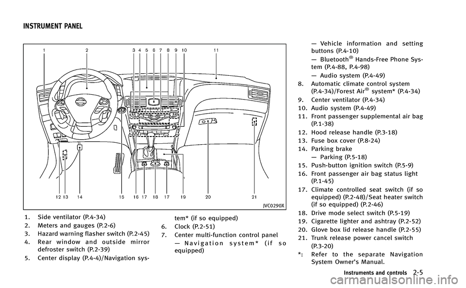
JVC0290X
1. Side ventilator (P.4-34)
2. Meters and gauges (P.2-6)
3. Hazard warning flasher switch (P.2-45)
4. Rear window and outside mirrordefroster switch (P.2-39)
5. Center display (P.4-4)/Navigation sys- tem* (if so equipped)
6. Clock (P.2-51)
7. Center multi-function control panel —Navigation system* (if so
equipped) —
Vehicle information and setting
buttons (P.4-10)
— Bluetooth
®Hands-Free Phone Sys-
tem (P.4-88, P.4-98)
— Audio system (P.4-49)
8. Automatic climate control system (P.4-34)/Forest Air
®system* (P.4-34)
9. Center ventilator (P.4-34)
10. Audio system (P.4-49)
11. Front passenger supplemental air bag (P.1-38)
12. Hood release handle (P.3-18)
13. Fuse box cover (P.8-24)
14. Parking brake —Parking (P.5-18)
15. Push-button ignition switch (P.5-9)
16. Front passenger air bag status light (P.1-45)
17. Climate controlled seat switch (if so equipped) (P.2-48)/Seat heater switch
(if so equipped) (P.2-46)
18. Drive mode select switch (P.5-19)
19. Cigarette lighter and ashtray (P.2-52)
20. Glove box lid release handle (P.2-55)
21. Trunk release power cancel switch (P.3-20)
*: Refer to the separate Navigation System Owner’s Manual.
Instruments and controls2-5
INSTRUMENT PANEL
Page 127 of 530

2-42Instruments and controls
.Never leave the light switch on when the
hybrid system is not running for a
periods of time even if the headlights
turn off automatically.
Daytime running light system (Ca-
nada only)
The daytime running lights automatically
illuminate when the hybrid system is
started with the parking brake released.
The daytime running lights operate with
the headlight switch in the OFF position or
in the
position. Turn the headlight
switch to theposition for full illumina-
tion when driving at night.
If the parking brake is applied before the
hybrid system is started, the daytime
running lights do not illuminate. The day-
time running lights illuminate once the
parking brake is released. The daytime
running lights will remain on until the
ignition switch is pushed to the OFF
position.
Adaptive Front lighting System
(AFS) (if so equipped)
The Adaptive Front lighting System (AFS)
will automatically adjust the headlights (low beam) toward the turning direction to
improve the driver’s view. When the head-
light switch is ON and the driver operates
the steering wheel in a turn, the AFS
system will be activated.
The AFS will operate:
.
Right-side headlight
— When the headlight switch is ON
— When the selector lever is in any
position other than P (Park) or R
(Reverse)
— When the steering wheel is turned
clockwise
. Left-side headlight
— When the headlight switch is ON
— When the selector lever is in any
position other than P (Park) or R
(Reverse)
— When the vehicle is driven at a
speed above 16 MPH (25km/h).
However, when the vehicle’s speed
decreases below 3 MPH (5 km/h) it
will stop.
— When the steering wheel is turned
counterclockwise
SIC4333
To turn the AFS off, push the AFS switch.
(The AFS OFF indicator light will illuminate.)
Push the switch again to turn the system
on again.
AFS will also adjust the headlight to a
proper axis automatically, depending on
the number of occupants in the vehicle, the
load the vehicle is carrying and the road
conditions.
If the AFS OFF indicator light blinks after
the ignition switch has been pushed to the
ON position, this may indicate that the AFS
is not functioning properly. Have the
system checked by an INFINITI retailer.
When the hybrid system is started, the
Page 136 of 530

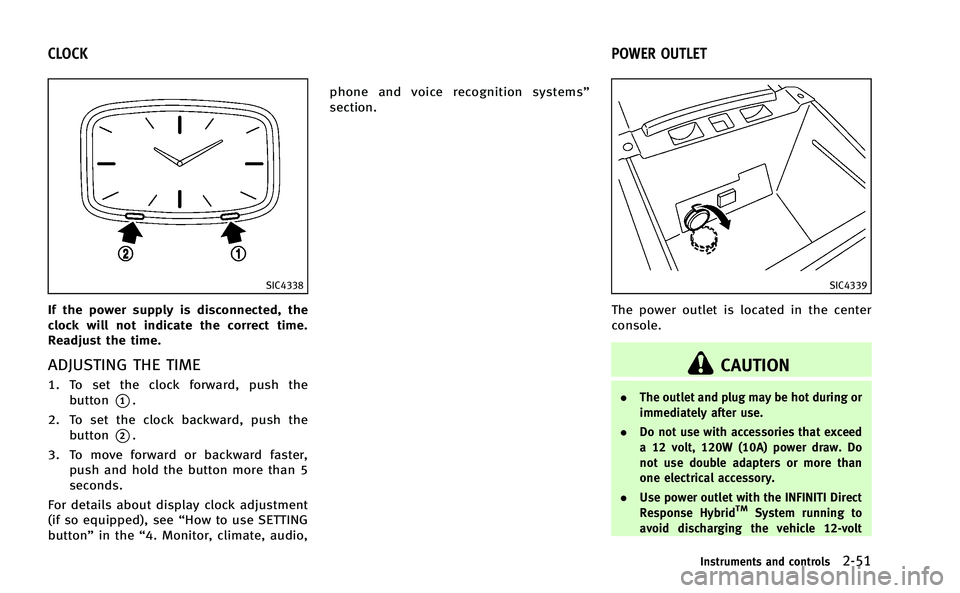
SIC4338
If the power supply is disconnected, the
clock will not indicate the correct time.
Readjust the time.
ADJUSTING THE TIME
1. To set the clock forward, push thebutton
*1.
2. To set the clock backward, push the button
*2.
3. To move forward or backward faster, push and hold the button more than 5
seconds.
For details about display clock adjustment
(if so equipped), see “How to use SETTING
button” in the“4. Monitor, climate, audio, phone and voice recognition systems”
section.
SIC4339
The power outlet is located in the center
console.
CAUTION
.
The outlet and plug may be hot during or
immediately after use.
. Do not use with accessories that exceed
a 12 volt, 120W (10A) power draw. Do
not use double adapters or more than
one electrical accessory.
. Use power outlet with the INFINITI Direct
Response Hybrid
TMSystem running to
avoid discharging the vehicle 12-volt
Instruments and controls2-51
CLOCK POWER OUTLET
Page 178 of 530

CAUTION
.If fuel is spilled on the vehicle body,
flush it away with water to avoid paint
damage.
. Insert the cap straight into the fuel-filler
tube, then tighten until the fuel-filler cap
a single click is heard. Failure to tighten
the fuel-filler cap properly may cause the
malfunction indicator light (MIL) to
illuminate. If thelight illuminates
because the fuel-filler cap is loose or
missing, tighten or install the cap and
continue to drive the vehicle. The
light should turn off after a few driving
trips. If thelight does not turn off
after a few driving trips, have the vehicle
inspected by an INFINITI retailer.
. The LOOSE FUEL CAP warning will appear
if the fuel-filler cap is not properly
tightened. It may take a few driving
trips for the message to be displayed.
Failure to tighten the fuel-filler cap
properly after the LOOSE FUEL CAP
warning appears may cause the
Malfunction Indicator Light (MIL) to
illuminate.
JVP0046X
To remove the fuel-filler cap:
1. Turn the fuel-filler cap counterclockwise
to remove.
2. Put the fuel-filler cap on the cap holder
*Awhile refueling.
To install the fuel-filler cap:
1. Insert the fuel-filler cap straight into the fuel-filler tube.
2. Turn the fuel-filler cap clockwise until a single click is heard.
SPA2832
Loose fuel cap warning
The LOOSE FUEL CAP warning appears on
the dot matrix liquid crystal display when
the fuel-filler cap is not tightened correctly
after the vehicle has been refueled. It may
take a few driving trips for the warning to
be displayed. To turn off the warning,
perform the following steps:
1. Remove and install the fuel-filler cap assoon as possible. (See “Fuel-filler cap”
earlier in this section.)
2. Tighten the fuel-filler cap until it clicks.
3. Push the reset switch
*Aon the right
side of the combination meter for about
Pre-driving checks and adjustments3-23
Page 207 of 530

4-20Monitor, climate, audio, phone and voice recognition systems
.Image Viewer
Depending on the vehicle equipment,
pushing SETTING button will display the
following items.
. Display
. Clock
SAA2486
Display settings (models with na-
vigation system)
The display as illustrated will appear when
pushing the SETTING button and selecting
the “Others” key, and then selecting the
“Display” key.
Also, the “Display” screen will display
when the DISP button on the control panel
is pushed.
Display Adjustment:
To adjust the display settings, select the
“Display Adjustment” key. The following
settings are available. .
Display
To turn off the screen, push the ENTER
button and turn the “Display”indicator off.
The other method is to push and hold the
“
OFF” button for more than 2 seconds.
When any mode button is pushed with the
screen off, the screen turns on for further
operation. The screen will turn off auto-
matically 5 seconds after the operation is
finished.
To turn on the screen, set this item to the
ON position, or push and hold the “
OFF”button.
. Brightness/Contrast/Background Color
To adjust the brightness and contrast of
the screen, select the “Brightness” or
“Contrast” key.
Then, you can adjust the brightness and
the contrast using the INFINITI controller.
For information on the “Background Color”
key, refer to the separate Navigation
System Owner’s Manual.
Color Theme:
Choose the theme color of the menu screen
from “Black”, “Brown” or“Silver”.
Page 210 of 530

SAA2487
Clock settings (models with navi-
gation system)
The display as illustrated will appear when
pushing the SETTING button and selecting
the“Others” key, and then selecting the
“Clock” key.
The clock settings display cannot be
operated while driving. Stop the vehicle
in a safe place and apply the parking brake
before setting the clock.
On-screen Clock:
When this item is turned to ON, a clock is
always displayed in the upper right corner
of the screen. This clock will indicate the time almost
exactly because it is always adjusted by
the GPS system.
Clock Format (24h):
When this item is turned to ON, the 24-
hour clock is displayed. When this item is
not turned to ON, the 12-hour clock is
displayed.
Offset (hour)/(min):
Adjust the time by increasing or decreasing
per hour or per minute.
Daylight Saving Time:
Turn this item to ON for daylight saving
time application.
Time Zone:
Choose the time zone from the following
. Pacific
. Mountain
. Central
. Eastern
. Atlantic
. Newfoundland
. Hawaii
. Alaska
SAA3007
Models with navigation system
JVH0252X
Models without navigation system
Monitor, climate, audio, phone and voice recognition systems4-23
Page 437 of 530

6-6In case of emergency
SCE0504
2. Loosen each wheel nut one or two turnsby turning counterclockwise with the
wheel nut wrench. Do not remove the
wheel nuts until the tire is off the
ground.
3. Carefully raise the vehicle until the tire clears the ground. To lift the vehicle,
securely hold the jack lever and rod
with both hands as shown above.
Remove the wheel nuts, and then
remove the tire.
SCE0661
Installing the spare tire
The T-type spare tire is designed for
emergency use. (See specific instructions
under the heading “Wheels and tires” in
the “8. Maintenance and do-it-yourself”
section.)
1. Clean any mud or dirt from the surface
between the wheel and hub.
2. Carefully put the spare tire on and tighten the wheel nuts finger tight.
3. With the wheel nut wrench, tighten wheel nuts alternately and evenly in the
sequence as illustrated (
*1,*2,*3,
*4,*5) until they are tight.
Page 469 of 530

8-14Maintenance and do-it-yourself
.Waste oil must be disposed of
properly.
.Check your local regulations.
4. (Perform steps 4 to 7 only when the engine oil filter change is needed.)
Loosen the oil filter
*2with an oil filter
wrench. Remove the oil filter by turning
it by hand.
5. Wipe the engine oil filter mounting surface with a clean rag.
CAUTION
Be sure to remove any old rubber gasket
remaining on the mounting surface of the
engine. Failure to do so could lead to engine
damage.
6. Coat the gasket on the new filter with
clean engine oil.
7. Screw in the oil filter clockwise until a slight resistance is felt, then tighten
additionally more than 2/3 turn.
Oil filter tightening torque:11 to 15 ft-lb
(14.7 to 20.5 N·m) 8. Clean and re-install the drain plug with
a new washer. Securely tighten the
drain plug with a wrench.
Drain plug tightening torque:22 to 29 ft-lb
(29 to 39 N·m)
Do not use excessive force.
9. Refill engine with recommended oil and install the oil filler cap securely.
CAUTION
The dipstick must be inserted in place to
prevent oil spillage from the dipstick hole
while filling the engine with oil.
See “Capacities and recommended
fuel/lubricants” in the“9. Technical
and consumer information” section for
drain and refill capacity. The drain and
refill capacity depends on the oil
temperature and drain time. Use these
specifications for reference only. Al-
ways use the dipstick to determine the
proper amount of oil in the engine.
10. Start the engine and check for leakage around the drain plug and the oil filter.
Correct as required. 11. Turn the engine off and wait more than
15 minutes. Check the oil level with the
dipstick. Add engine oil if necessary.
After the operation
1. Install the engine undercover intoposition as the following steps.
a. Pull the center of the small plastic
clip out.
b. Hold the engine undercover into position.
c. Insert the clip through the under- cover into the hole in the frame, then
push the center of the clip in to lock
the clip in place.
d. Install the other bolts that hold the undercover in place. Be careful not
to strip the bolts or over-tighten
them.
2. Lower the vehicle carefully to the ground.
3. Dispose of waste oil and filter properly.
WARNING
. Prolonged and repeated contact with
used engine oil may cause skin cancer.