headlights INFINITI Q50 HYBRID 2018 User Guide
[x] Cancel search | Manufacturer: INFINITI, Model Year: 2018, Model line: Q50 HYBRID, Model: INFINITI Q50 HYBRID 2018Pages: 440, PDF Size: 2.8 MB
Page 132 of 440

2-46Instruments and controls
ate, turn the heater off and have the
system checked. It is recommended
that you visit an INFINITI retailer for
this service.
Push the CLIMATE button and touch
[Steering Heater] on the lower display to
turn on or off the steering wheel heating
manually. The steering wheel heating will
turn off automatically 30 minutes after it
has been turned on. When the steering
wheel heating is turned on, the indicator
above [Steering Heater] will turn on.
If the surface temperature of the steering
wheel is above the temperature within which
the system is designed to operate, the
system will not heat the steering wheel. This
is not a malfunction.
Automatic steering wheel heating can be
turned on or off from the climate control
settings screen. For details, see the Infiniti
InTouch Owner’s Manual.
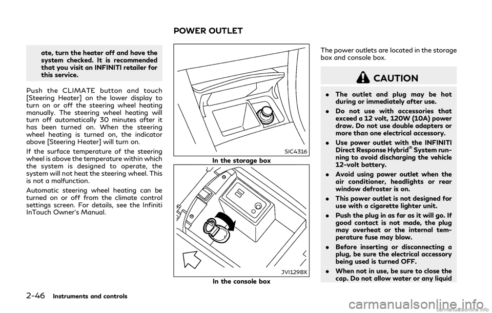
SIC4316
In the storage box
JVI1298X
In the console box The power outlets are located in the storage
box and console box.
CAUTION
.
The outlet and plug may be hot
during or immediately after use.
. Do not use with accessories that
exceed a 12 volt, 120W (10A) power
draw. Do not use double adapters or
more than one electrical accessory.
. Use power outlet with the INFINITI
Direct Response Hybrid
®System run-
ning to avoid discharging the vehicle
12-volt battery.
. Avoid using power outlet when the
air conditioner, headlights or rear
window defroster is on.
. This power outlet is not designed for
use with a cigarette lighter unit.
. Push the plug in as far as it will go. If
good contact is not made, the plug
may overheat or the internal tem-
perature fuse may blow.
. Before inserting or disconnecting a
plug, be sure the electrical accessory
being used is turned OFF.
. When not in use, be sure to close the
cap. Do not allow water or any liquid
POWER OUTLET
Page 142 of 440

2-56Instruments and controls
3. Release the moonroof switch after themoonroof moves slightly up and down.
4. Push and hold the switch to the open position
to fully tilt the moonroof
down.
5. Check if the moonroof switch operates normally.
If the moonroof does not operate properly
after performing the procedure above, have
your moonroof checked and repaired. It is
recommended you visit an INFINITI retailer
for this service.
JVI0656X
MAP LIGHTS
Push the button as illustrated to turn the
light on or off.
JVI0726X
CONSOLE LIGHT (if so equipped)
The console light will turn on whenever the
front parking lights or headlights are illumi-
nated.
INTERIOR LIGHTS
Page 167 of 440

turning the mechanical key in a door lock.
(See “Doors” (P.3-4).)
Opening moonroof
The moonroof can be opened by pushing the
UNLOCKbuttonon the Intelligent
Key. This function will not operate while the
moonroof timer is activated or when the
windows need to be initialized.
To open the moonroof, push the UNLOCK
buttonon the Intelligent Key for
about 3 seconds after the door is unlocked.
To stop opening, release the UNLOCK
button.
Opening trunk lid
1. Push the TRUNKbuttonon the
Intelligent Key for more than 1 second.
2. The trunk will unlatch.
3. Raise the trunk lid to open the trunk.
Using panic alarm
If you are near your vehicle and feel
threatened, you may activate the alarm to
call attention as follows:
1. Push the PANIC
buttonon the key
for more than 1 second.
2. The theft warning alarm and headlights will stay on for 25 seconds. 3. The panic alarm stops when:
.It has run for 25 seconds, or.Any of the buttons on the Intelligent
Key are pushed. (Note: PANIC
buttonor TRUNKbuttonshould be pushed for more than 1
second.)
Remote engine start
The remote engine startbuttonis on
the Intelligent Key if the vehicle has remote
engine start function. This function allows
the engine to start from outside the vehicle.
See “Remote engine start” (P.3-19) for more
details.
Setting hazard indicator and horn
mode
This vehicle is set in hazard indicator and
horn mode when you first receive the vehicle.
In hazard indicator and horn mode, when the
LOCK
buttonis pushed, the hazard
indicator flashes twice and the horn chirps
once. When the UNLOCK
buttonis
pushed, the hazard indicator flashes once.
If horns are not necessary, the system can be
switched to the hazard indicator mode.
In hazard indicator mode, when the LOCK
buttonis pushed, the hazard indicator
flashes twice. When the UNLOCK
buttonis pushed, neither the hazard indicator nor the horn operates.
Pre-driving checks and adjustments3-17
Page 178 of 440

3-28Pre-driving checks and adjustments
2. To block glare from the side, remove thesun visor from the center mount and
swing the visor to the side
.
3. Slide the sun visor
in or out as needed.
SPA2447
INSIDE MIRROR
Adjust the height and the angle of the inside
mirror to the desired position.
SPA2450-A
Automatic anti-glare type
The inside mirror is designed so that it
automatically changes reflection according
to the intensity of the headlights of the
following vehicle.
The anti-glare system will be automatically
turned on when the ignition switch is pushed
to the ON position.
The anti-glare system also operates for the
outside mirrors (if so equipped).
When the anti-glare system is turned on, the
indicator light
will illuminate and excessive
glare from the headlights of the vehicle
behind you will be reduced.
Push the “*” switch
to make the inside
MIRRORS
Page 180 of 440

3-30Pre-driving checks and adjustments
4. The outside mirror surface moves down-ward.
When one of the following conditions has
occurred, the outside mirror surface will
return to its original position.
. The shift lever is moved to any position
other than R (Reverse).
. The outside mirror control switch is set to
the center position.
. The ignition switch is pushed to the OFF
position.
Automatic anti-glare (if so
equipped)
The outside mirrors are designed so that
they automatically change reflection ac-
cording to the intensity of the headlights of
the vehicle following you.
The anti-glare system will be automatically
turned on when the ignition switch is placed
in the ON position.
SIC3869
VANITY MIRROR
To use the front vanity mirror, pull down the
sun visor and pull up the cover. The automatic drive positioner system has
two features:
.
Entry/exit function
. Memory storage
ENTRY/EXIT FUNCTION
This system is designed so that the driver’s
seat and steering column will automatically
move when the shift lever is in the P (Park)
position. This allows the driver to get into
and out of the driver’s seat more easily.
The driver’s seat will slide backward and the
steering wheel will move up when the
driver’s door is opened with the ignition
switch in the LOCK position.
The driver’s seat and steering wheel will
return to the previous positions when the
ignition switch is pushed to the ACC posi-
tion.
The driver’s seat will not return to the
previous positions if the seat or steering
adjusting switch is operated when the seat is
at the exit position.
Cancel or activate entry/exit func-
tion
All the following conditions must be met
before cancelling or activating the entry/exit
function.
.The ignition switch is placed in the LOCK
position.
AUTOMATIC DRIVE POSITIONER
Page 216 of 440

5-30Starting and driving
— When the vehicle’s traveling di-rection does not align with the
lane marker.
— When traveling close to the ve- hicle in front of you, which ob-
structs the lane camera unit
detection range.
— When rain, snow, dirt or object adheres to the windshield in front
of the lane camera unit.
— When the headlights are not bright due to dirt on the lens or
if the aiming is not adjusted
properly.
— When strong light enters the lane camera unit. (For example, the
light directly shines on the front
of the vehicle at sunrise or sun-
set.)
— When a sudden change in bright- ness occurs. (For example, when
the vehicle enters or exits a tunnel
or under a bridge.)
— When entering or exiting toll- gates.
— When driving on roads with a widening or narrowing lane width.
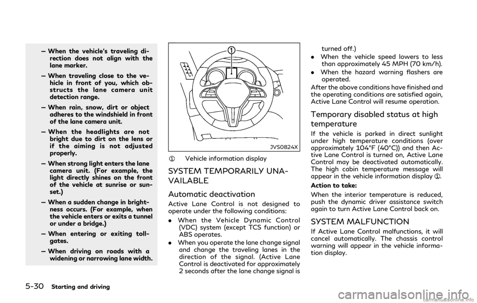
JVS0824X
Vehicle information display
SYSTEM TEMPORARILY UNA-
VAILABLE
Automatic deactivation
Active Lane Control is not designed to
operate under the following conditions:
. When the Vehicle Dynamic Control
(VDC) system (except TCS function) or
ABS operates.
. When you operate the lane change signal
and change the traveling lanes in the
direction of the signal. (Active Lane
Control is deactivated for approximately
2 seconds after the lane change signal is turned off.)
. When the vehicle speed lowers to less
than approximately 45 MPH (70 km/h).
. When the hazard warning flashers are
operated.
After the above conditions have finished and
the operating conditions are satisfied again,
Active Lane Control will resume operation.
Temporary disabled status at high
temperature
If the vehicle is parked in direct sunlight
under high temperature conditions (over
approximately 104°F (40°C)) and then Ac-
tive Lane Control is turned on, Active Lane
Control may be deactivated automatically.
The high cabin temperature message will
appear in the vehicle information display
.
Action to take:
When the interior temperature is reduced,
push the dynamic driver assistance switch
again to turn Active Lane Control back on.
SYSTEM MALFUNCTION
If Active Lane Control malfunctions, it will
cancel automatically. The chassis control
warning will appear in the vehicle informa-
tion display.
Page 223 of 440

seams or lines remaining after
road repairs. (The LDW and LDP
systems could detect these items
as lane markers.)
— On roads where the traveling lane merges or separates.
— When the vehicle’s traveling di- rection does not align with the
lane marker.
— When traveling close to the ve- hicle in front of you, which ob-
structs the lane camera unit
detection range.
— When rain, snow or dirt adheres to the windshield in front of the
lane camera unit.
— When the headlights are not bright due to dirt on the lens or
if the aiming is not adjusted
properly.
— When strong light enters the lane camera unit. (For example, the
light directly shines on the front
of the vehicle at sunrise or sun-
set.)
— When a sudden change in bright- ness occurs. (For example, when
the vehicle enters or exits a tunnel
or under a bridge.) .
Excessive noise will interfere with the
warning chime sound, and the chime
may not be heard.
JVS0826X
Warnings and indicators (on the vehicle
information display)
Dynamic driver assistance switch
SYSTEM TEMPORARILY UNA-
VAILABLE
Condition A
Under the following conditions, If the “LDP
currently unavailable” message appears in
the vehicle information display, a chime will
sound and the LDP system will be turned off
automatically.
.When the VDC system (except TCS
function) or ABS operates.
Starting and driving5-37
Page 238 of 440

5-52Starting and driving
and the BSI system may not operate
properly.— On roads where there are multi- ple parallel lane markers; lane
markers that are faded or not
painted clearly; yellow painted
lane markers; nonstandard lane
markers; lane markers covered
with water, dirt, snow, etc.
— On roads where discontinued lane markers are still detectable.
— On roads where there are sharp curves.
— On roads where there are sharply contrasting objects, such as sha-
dows, snow, water, wheel ruts,
seams or lines remaining after
road repairs.
— On roads where the traveling lane merges or separates.
— When the vehicle’s traveling di- rection does not align with the
lane markers.
— When traveling close to the ve- hicle in front of you, which ob-
structs the lane camera unit
detection range.
— When rain, snow or dirt adheres to the windshield in front of a lane camera unit.
— When the headlights are not bright due to dirt on the lens or
if aiming is not adjusted properly.
— When strong light enters a lane camera unit. (For example: light
directly shines on the front of the
vehicle at sunrise or sunset.)
— When a sudden change in bright- ness occurs. (For example: when
the vehicle enters or exits a tunnel
or under a bridge.)
. Do not use the BSI system under the
following conditions because the sys-
tem may not function properly.
— During bad weather. (For exam- ple: rain, fog, snow, etc.)
— When driving on slippery roads, such as on ice or snow, etc.
— When driving on winding or un- even roads.
— When there is a lane closure due to road repairs.
— When driving in a makeshift or temporary lane.
— When driving on roads where the lane width is too narrow. — When driving with a tire that is
not within normal tire conditions
(for example, tire wear, low tire
pressure, installation of tire
chains, non-standard wheels).
— When the vehicle is equipped with non-original steering parts or sus-
pension parts.
. Excessive noise (for example, audio
system volume, open vehicle window)
will interfere with the chime sound,
and it may not be heard.
Page 329 of 440

Before attempting to jump start the vehicle,
make sure the fuel tank is not empty and the
correct starting procedure is followed. See
“Starting the INFINITI Direct Response
Hybrid
®System” (P.5-14). Do not drive the
vehicle on battery power only if the fuel tank
is empty. The Lithium ion (Li-ion) battery will
become discharged and the INFINITI Direct
Response Hybrid
®System will turn off.
CONFIRM BATTERY IS DIS-
CHARGED
If any of the following conditions occurs, the
12-volt battery might discharged:
. The instrument cluster and/or headlights
are not normal brightness.
. Audio accessories cannot be turned on.
. The hybrid system does not become
READY to drive mode.
. The ignition switch cannot be placed in
the ON position.
Check the following if you notice above
conditions.
1. Check that the 12-volt battery terminals are tight and clean. See “12-volt battery”
(P.8-14). The 12-volt battery is located
on the left hand side of the trunk behind
an access panel. If the 12-volt battery
terminals are loose, it is recommended
you contact an INFINITI retailer. 2. If the 12-volt battery terminals are tight
and clean, try to jump start the vehicle.
See “Jump starting” (P.6-5).
If the hybrid system still does not start, it is
recommended that you contact an INFINITI
retailer. To start your INFINITI Direct Response
Hybrid
®System with a booster battery, the
instructions and precautions below must be
followed.
Jump starting provides power to the 12 volt
system to allow the electrical systems to
operate. The electrical systems must be
operating to allow the Lithium ion (Li-ion)
battery to be charged. Jump starting does
not charge the Li-ion battery.
WARNING
. If done incorrectly, jump starting can
lead to a 12-volt battery explosion,
resulting in severe injury or death. It
could also damage your vehicle.
. Explosive hydrogen gas is always
present in the vicinity of the 12-volt
battery. Make sure that the vent
tube is mounted.
. Do not allow battery fluid to come
into contact with eyes, skin, clothing
or painted surfaces. Battery fluid is a
corrosive sulfuric acid solution which
can cause severe burns. If the fluid
should come into contact with any-
thing, immediately flush the con-
tacted area with water.
. Keep the 12-volt battery out of the
reach of children.
In case of emergency6-5
IF THE VEHICLE DOES NOT STARTJUMP STARTING
Page 347 of 440

8 Do-it-yourself
Maintenance precautions ................................................ 8-2
Engine compartment check locations ......................... 8-3VQ35HR engine ........................................................... 8-3
Engine cooling system ..................................................... 8-5 Checking engine coolant level .................................. 8-6
Changing engine coolant ........................................... 8-7
Inverter cooling system ................................................... 8-7 Checking inverter coolant level ................................ 8-8
Changing inverter coolant ......................................... 8-9
Engine oil ........................................................................\
..... 8-9
Checking engine oil level ............................................ 8-9
Changing engine oil and oil filter .......................... 8-10
Automatic Transmission Fluid (ATF) ......................... 8-12
Brake fluid ........................................................................\
. 8-12
Window washer fluid ..................................................... 8-13
12-volt battery ................................................................. 8-14
Checking battery fluid level .................................... 8-15
Jump starting .............................................................. 8-15
Spark plugs ........................................................................\
8-15 Replacing spark plugs ............................................... 8-16
Air cleaner ........................................................................\
.. 8-16 Windshield wiper blades ............................................... 8-17
Cleaning ...................................................................... 8-17
Replacing .................................................................... 8-18
Brakes ........................................................................\
........ 8-18 Self-adjusting brakes .............................................. 8-18
Brake pad wear warning ....................................... 8-18
Fuses ........................................................................\
.......... 8-19 Engine compartment and trunk ........................... 8-19
Passenger compartment ....................................... 8-20
Intelligent Key battery replacement .......................... 8-21
Lights ........................................................................\
........ 8-24 Headlights .................................................................. 8-25
Exterior and interior lights .................................... 8-25
Wheels and tires ............................................................ 8-28 Tire pressure ............................................................. 8-28
Tire labeling ............................................................... 8-32
Types of tires ........................................................... 8-34
Tire chains .................................................................. 8-35
Changing wheels and tires .................................... 8-36
Jacking up the vehicle and replacing tires ........ 8-39