INFINITI Q60 2019 Owners Manual
Manufacturer: INFINITI, Model Year: 2019, Model line: Q60, Model: INFINITI Q60 2019Pages: 468, PDF Size: 2.18 MB
Page 441 of 468

DIMENSIONS
in (mm)
Overall length 184.4 (4,685)
Overall width 72.8 (1,850)
Overall height 54.9 (1,395) 54.5 (1,385)*1
Front tread 61.2 (1,555)
Rear tread 61.8 (1,570)*2 62.2 (1,580)*3
62.4 (1,585)*4
Wheelbase 112.2 (2,850)
*1: Two-Wheel Drive (2WD) models with VR30DDTT engine
*2: 275/30R20 rear tire models
*3: 2.0L turbo gasoline engine models
*4: VR30DDTT engine with 255/35R20 or 255/40RF19 tire models
Technical and consumer information10-13
Page 442 of 468
10-14Technical and consumer information
If you plan to travel in another country,you
should first find out if the fuel available is
suitable for your vehicle’s engine.
Using fuel with too low an octane rating may
cause engine damage. All gasoline vehicles
must be operated with unleaded gasoline.
Therefore, avoid taking your vehicle to areas
where appropriate fuel is not available.
When transferring the registration of your
vehicle to another country, state, province
or district, it may be necessary to modify the
vehicle to meet local laws and regulations.
The laws and regulations for motor vehicle
emission control and safety standards vary
according to the country, state, province or
district; therefore, vehicle specifications may
differ.
When any vehicle is to be taken into
another country, state, province or district
and registered, its modifications, transpor-
tation, and registration are the responsi-
bility of the user. INFINITI is not responsible
for any inconvenience that may result.
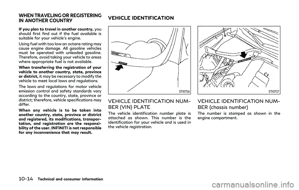
STI0716
VEHICLE IDENTIFICATION NUM-
BER (VIN) PLATE
The vehicle identification number plate is
attached as shown. This number is the
identification for your vehicle and is used in
the vehicle registration.
STI0717
VEHICLE IDENTIFICATION NUM-
BER (chassis number)
The number is stamped as shown in the
engine compartment.
WHEN TRAVELING OR REGISTERING
IN ANOTHER COUNTRYVEHICLE IDENTIFICATION
Page 443 of 468
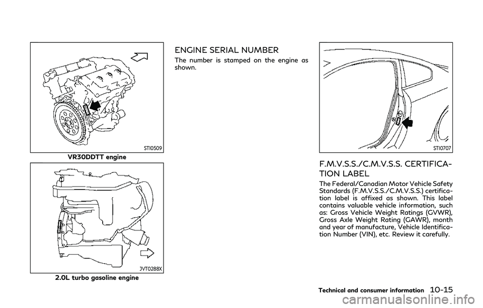
STI0509
VR30DDTT engine
JVT0288X
2.0L turbo gasoline engine
ENGINE SERIAL NUMBER
The number is stamped on the engine as
shown.
STI0707
F.M.V.S.S./C.M.V.S.S. CERTIFICA-
TION LABEL
The Federal/Canadian Motor Vehicle Safety
Standards (F.M.V.S.S./C.M.V.S.S.) certifica-
tion label is affixed as shown. This label
contains valuable vehicle information, such
as: Gross Vehicle Weight Ratings (GVWR),
Gross Axle Weight Rating (GAWR), month
and year of manufacture, Vehicle Identifica-
tion Number (VIN), etc. Review it carefully.
Technical and consumer information10-15
Page 444 of 468
10-16Technical and consumer information
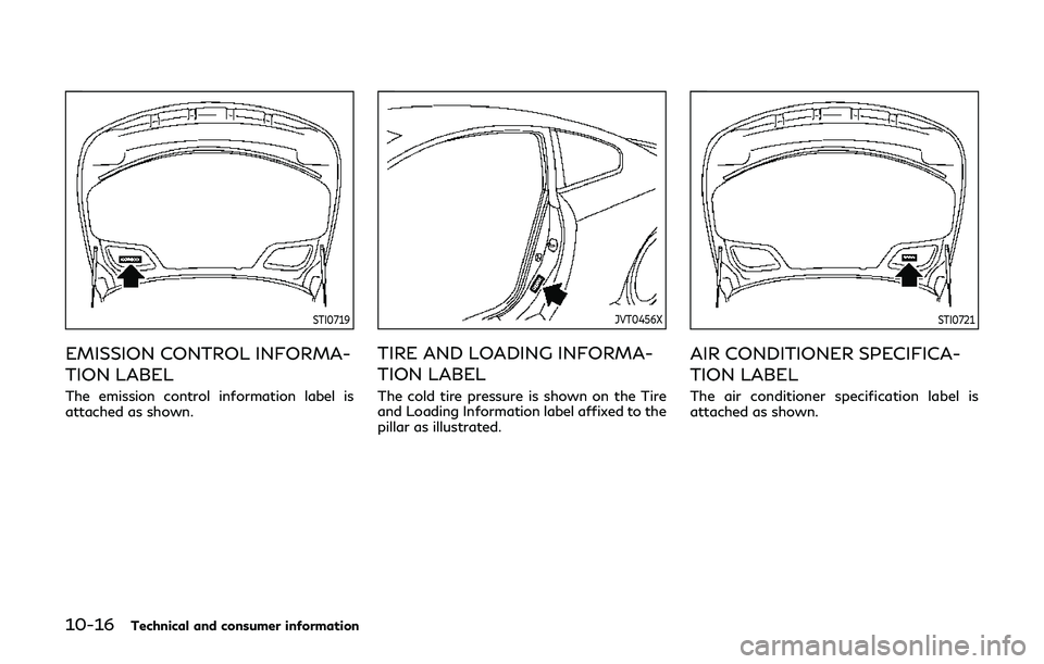
STI0719
EMISSION CONTROL INFORMA-
TION LABEL
The emission control information label is
attached as shown.
JVT0456X
TIRE AND LOADING INFORMA-
TION LABEL
The cold tire pressure is shown on the Tire
and Loading Information label affixed to the
pillar as illustrated.
STI0721
AIR CONDITIONER SPECIFICA-
TION LABEL
The air conditioner specification label is
attached as shown.
Page 445 of 468
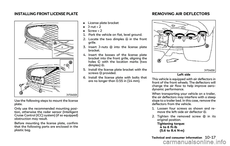
JVT0450X
Use the following steps to mount the license
plate.
Only use the recommended mounting posi-
tion, otherwise the radar sensor (Intelligent
Cruise Control (ICC) system) (if so equipped)
obstruction may result.
Before mounting the license plate, confirm
that the following parts are enclosed in the
plastic bag..
License plate bracket
. J-nut × 2
. Screw × 2
1. Park the vehicle on flat, level ground.
2. Locate the two dimples
in the front
grille.
3. Insert J-nuts
into the license plate
bracket.
4. Insert the bosses of the license plate bracket into the front grille, aligning the
holes
with the location marks (two
dimples).
5. Install the license plate bracket with the screws
provided.
6. Install the license plate with bolts that are no longer than 0.55 in (14 mm).JVT0455X
Left side
This vehicle is equipped with air deflectors in
front of the front wheels. The deflectors will
change the air flow to help improve aero-
dynamic performance.
When transporting your vehicle on a trailer,
the air deflectors may interfere with a steep
slope to a trailer bed. In this case, remove the
deflectors from the vehicle.
1. Loosen four screws as shown and re- move the left-side air deflector
.
2. Tighten the removed screw
in its
original position.
Tightening torque:
4 to 6 ft-lb
(5.6 to 8.4 N·m)
Technical and consumer information10-17
INSTALLING FRONT LICENSE PLATEREMOVING AIR DEFLECTORS
Page 446 of 468
10-18Technical and consumer information
3. Perform the same procedure to removethe right-side air deflector.
4. Store the two air deflectors and six screws to reinstall in the reverse order.
5. When reinstalling, make sure all eight screws are firmly tightened on both air
deflectors.
Tightening torque:4 to 6 ft-lb
(5.6 to 8.4 N·m)
WARNING
.It is extremely dangerous to
ride in a cargo area inside the
vehicle. In a collision, people
riding in these areas are more
likely to be seriously injured or
killed.
.Do not allow people to ride in
any area of vehicle that is not
equipped with seats and seat
belts.
.Be sure everyone in your vehicle
is in a seat and using a seat belt
properly.
TERMS
It is important to familiarize yourself
with the following terms before load-
ing your vehicle:
.Curb Weight (actual weight ofyour vehicle) - vehicle weight in-
cluding: standard and optional
equipment, fluids, emergency
tools, and spare tire assembly. This
weight does not include passen- gers and cargo.
.GVW (Gross Vehicle Weight) -
curb weight plus the combined
weight of passengers and cargo.
.GVWR (Gross Vehicle Weight Rat-ing) - maximum total combined
weight of the unloaded vehicle,
passengers, luggage, hitch, trailer
tongue load and any other op-
tional equipment. This information
is located on the F.M.V.S.S./C.M.
V.S.S. label.
.GAWR (Gross Axle Weight Rating)- maximum weight (load) limit
specified for the front or rear axle.
This information is located on the
F.M.V.S.S./C.M.V.S.S. label.
.GCWR (Gross Combined Weight
Rating) - The maximum total
weight rating of the vehicle, pas-
sengers, cargo, and trailer.
.Vehicle Capacity Weight, Loadlimit, Total load capacity - max-
imum total weight limit specified
of the load (passengers and cargo)
for the vehicle. This is the max-
imum combined weight of occu-
VEHICLE LOADING INFORMATION
Page 447 of 468
pants and cargo that can be
loaded into the vehicle. If the
vehicle is used to tow a trailer,
the trailer tongue weight must be
included as part of the cargo load.
This information is located on the
Tire and Loading Information la-
bel.
.Cargo capacity - permissibleweight of cargo, the weight of
total occupants weight subtracted
from the load limit.
STI0365
VEHICLE LOAD CAPACITY
Do not exceed the load limit of your
vehicle shown as “The combined
weight of occupants and cargo” on
the Tire and Loading Information
label. Do not exceed the number of
occupants shown as “Seating Capa-
city” on the Tire and Loading Infor-
mation label.
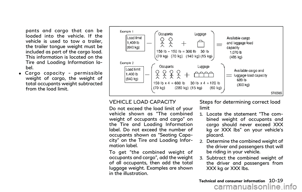
To get “the combined weight of
occupants and cargo”, add the weight
of all occupants, then add the total
luggage weight. Examples are shown
in the illustration.
Steps for determining correct load
limit
1.Locate the statement “The com-
bined weight of occupants and
cargo should never exceed XXX
kg or XXX lbs” on your vehicle’s
placard.
2.Determine the combined weight of
the driver and passengers that will
be riding in your vehicle.
3.Subtract the combined weight of
the driver and passengers from
XXX kg or XXX lbs.
Technical and consumer information10-19
Page 448 of 468
10-20Technical and consumer information
4.The resulting figure equals the
available amount of cargo and
luggage load capacity. For exam-
ple, if the XXX amount equals
1400 lbs. and there will be five
150 lb. passengers in your vehicle,
the amount of available cargo and
luggage load capacity is 650 lbs.
(1400 − 750 (5 x 150) = 650 lbs or
640 − 340 (5 x 70) = 300 kg.)
5.Determine the combined weight of
luggage and cargo being loaded on
the vehicle. That weight may not
safely exceed the available cargo
and luggage load capacity calcu-
lated in Step 4.
6.If your vehicle will be towing a
trailer, load from your trailer will
be transferred to your vehicle.
Consult this manual to determine
how this reduces the available
cargo and luggage load capacity
of your vehicle.
Before driving a loaded vehicle, con-
firm that you do not exceed the Gross
Vehicle Weight Rating (GVWR) or the
Gross Axle Weight Rating (GAWR) for your vehicle. (See “Measurement
of weights” (P.10-20).)
Also check tires for proper inflation
pressures. See the Tire and Loading
Information label.
LOADING TIPS
.The GVW must not exceed GVWR
or GAWR as specified on the F.M.
V.S.S./C.M.V.S.S. certification la-
bel.
.Do not load the front and rear axleto the GAWR. Doing so will exceed
the GVWR.
WARNING
.Properly secure all cargo to help
prevent it from sliding or shift-
ing. Do not place cargo higher
than the seatbacks. In a sudden
stop or collision, unsecured car-
go could cause personal injury.
.Do not load your vehicle any
heavier than the GVWR or the
maximum front and rear
GAWRs. If you do, parts of your vehicle can break, tire
damage could occur, or it can
change the way your vehicle
handles. This could result in loss
of control and cause personal
injury.
.Overloading could not only
shorten the life of your vehicle
and the tires, but also could
lead to hazardous vehicle hand-
ling and long braking distance.
This may cause a premature tire
malfunction, which could result
in a serious accident and perso-
nal injury. Failures caused by
overloading are not covered by
the vehicle’s warranty.
MEASUREMENT OF WEIGHTS
Secure loose items to prevent weight
shifts that could affect the balance of
your vehicle. When the vehicle is
loaded, drive to a scale and weigh
the front and the rear wheels sepa-
rately to determine axle loads. Indivi-
dual axle loads should not exceed
either of the gross axle weight ratings
Page 449 of 468
(GAWR). The total of the axle loads
should not exceed the gross vehicle
weight rating (GVWR). These ratings
are given on the vehicle certification
label. If weight ratings are exceeded,
move or remove items to bring all
weights below the ratings.Do not tow a trailer with your
vehicle.
FLAT TOWING
Towing your vehicle with all four wheels on
the ground is sometimes called flat towing.
This method is sometimes used when towing
a vehicle behind a recreational vehicle, such
as a motor home.
CAUTION
.
Failure to follow these guidelines can
result in severe transmission damage.
. Whenever flat towing your vehicle,
always tow forward, never back-
ward.
. DO NOT tow any Automatic Trans-
mission (AT) vehicle with all four
wheels on the ground (flat towing).
Doing so WILL DAMAGE internal
transmission parts due to lack of
transmission lubrication.
. DO NOT tow any All-Wheel Drive
(AWD) vehicle with any of the wheels
on the ground. Doing so may cause
serious and expensive damage to the
powertrain.
. For emergency towing procedures
refer to “Towing recommended by INFINITI” (P.6-23).
Automatic Transmission
All-Wheel Drive (AWD) models:
Do not tow an AWD vehicle with any of the
wheels on the ground.
Two-Wheel Drive (2WD) models:
To tow a vehicle equipped with an automatic
transmission, an appropriate vehicle dolly
MUST
be placed under the towed vehicle’s
drive wheels. Alwaysfollow the dolly man-
ufacturer’s recommendations when using
their product.
Technical and consumer information10-21
TOWING A TRAILER
Page 450 of 468
10-22Technical and consumer information
DOT (Department Of Transportation) Qual-
ity Grades: All passenger car tires must
conform to federal safety requirements in
addition to these grades.
Quality grades can be found where applic-
able on the tire sidewall between tread
shoulder and maximum section width. For
example:
Treadwear 200 Traction AA Temperature A
TREADWEAR
The treadwear grade is a comparative rating
based on the wear rate of the tire when
tested under controlled conditions on a
specified government test course. For ex-
ample, a tire graded 150 would wear one
and one-half (1 1/2) times as well on the
government course as a tire graded 100.
The relative performance of tires depends
upon actual conditions of their use, however,
and may depart significantly from the norm
due to variations in driving habits, service
practices and differences in road character-
istics and climate.
TRACTION AA, A, B AND C
The traction grades, from highest to lowest,
are AA, A, B and C. Those grades represent
the tire’s ability to stop on wet pavement as
measured under controlled conditions on
specified government test surfaces of as-
phalt and concrete. A tire marked C may
have poor traction performance.
WARNING
The traction grade assigned to this tire is
based on straight-ahead braking trac-
tion tests, and does not include accel-
eration, cornering, hydroplaning, or peak
traction characteristics.
TEMPERATURE A, B AND C
The temperature grades A (the highest), B,
and C, representing the tire’s resistance to
the generation of heat and its ability to
dissipate heat when tested under controlled
conditions on a specified indoor laboratory
test wheel. Sustained high temperature can
cause the material of the tire to degenerate
and reduce tire life, and excessive tempera-
ture can lead to sudden tire failure. The
grade C corresponds to a level of perfor-
mance which all passenger car tires must
meet under the Federal Motor VehicleSafety Standard No. 109. Grades B and A
represent higher levels of performance on
the laboratory test wheel than the minimum
required by law.
WARNING
The temperature grade for this tire is
established for a tire that is properly
inflated and not overloaded. Excessive
speed, under-inflation, or excessive
loading, either separately or in combina-
tion, can cause heat build-up and possi-
ble tire failure.
UNIFORM TIRE QUALITY GRADING