display INFINITI Q60 COUPE 2021 Owner's Manual
[x] Cancel search | Manufacturer: INFINITI, Model Year: 2021, Model line: Q60 COUPE, Model: INFINITI Q60 COUPE 2021Pages: 492, PDF Size: 2.44 MB
Page 16 of 492

0-8Illustrated table of contents
JVC0969X
1. Paddle shifter (if so equipped) (P.5-18)
2. Meters and gauges (P.2-6)
— Clock (P.2-31)
3. Push-button ignition switch (P.5-11)
4. Center ventilator (P.4-34)5. Heater and air conditioner control
(P.4-34)
6. Upper touch screen display* (upper
display) and Navigation system* (if so
equipped)
— RearView Monitor (if so equipped)
(P.4-3)— Around View
®Monitor (if so
equipped) (P.4-11)
7. Lower touch screen display* (lower
display)
8. Rear window and outside mirror
defroster switch (P.2-37)
9. Front passenger supplemental air bag
(P.1-38)
10. Hood release handle (P.3-22)
11. Fuse box cover (P.8-17)
12. Parking brake (P.5-20)
13. Storage box (P.2-52) and power outlet
(P.2-47)
14. Seat heater switch (if so equipped)
(P.2-45)
15. Audio system*
16. Trunk release power cancel switch
(P.3-24)
17. Glove box (P.2-51)
*: Refer to the INFINITI InTouch
TMOwn-
er’s Manual.
INSTRUMENT PANEL
Page 17 of 492

JVC0428X
1. Tachometer (P.2-8)
2. Warning and indicator lights (P.2-12)
3. Speedometer (P.2-7)
4. Engine coolant temperature gauge
(P.2-8)
5. Vehicle information display (P.2-20)/Odometer/twin trip odometer (P.2-7)
6. Fuel gauge (P.2-9)
Illustrated table of contents0-9
METERS AND GAUGES
Page 75 of 492
SSS1016
SUPPLEMENTAL AIR BAG
WARNING LABELS
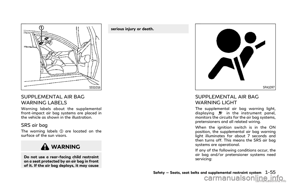
Warning labels about the supplemental
front-impact air bag systems are placed in
the vehicle as shown in the illustration.
SRS air bag
The warning labelsare located on the
surface of the sun visors.
WARNING
Do not use a rear-facing child restraint
on a seat protected by an air bag in front
of it. If the air bag deploys, it may causeserious injury or death.
SPA1097
SUPPLEMENTAL AIR BAG
WARNING LIGHT
The supplemental air bag warning light,
displayingin the instrument panel,
monitors the circuits for the air bag systems,
pretensioners and all related wiring.
When the ignition switch is in the ON
position, the supplemental air bag warning
light illuminates for about 7 seconds and
then turns off. This means the SRS air bag
systems are operational.
If any of the following conditions occur, the
air bag and/or pretensioner systems need
servicing:
Safety — Seats, seat belts and supplemental restraint system1-55
Page 79 of 492

2 Instruments and controls
Cockpit ................................................................................. 2-3
Instrument panel ............................................................... 2-5
Meters and gauges .......................................................... 2-6
Speedometer and odometer ..................................... 2-7
Tachometer ................................................................... 2-8
Engine coolant temperature gauge ....................... 2-8
Fuel gauge ..................................................................... 2-9
Compass (if so equipped) ............................................... 2-9
Zone variation change procedure ......................... 2-11
Warning lights, indicator lights and
audible reminders ............................................................ 2-12
Checking lights ........................................................... 2-13
Warning/indicator lights (red) ............................... 2-13
Warning/indicator lights (yellow) ......................... 2-15
Warning/indicator lights (other) ........................... 2-19
Audible reminders ..................................................... 2-20
Vehicle information display .......................................... 2-20
Indicators for operation .......................................... 2-23
Indicators for maintenance .................................... 2-26
Trip computer ............................................................. 2-29
Clock and outside air temperature ....................... 2-31
Security systems ............................................................. 2-32
Vehicle Security System .......................................... 2-32
INFINITI Vehicle Immobilizer System .................. 2-33Wiper and washer switch ............................................ 2-34
Rain-sensing auto wiper system ........................ 2-36
Rear window and outside mirror
defroster switch ............................................................. 2-37
Headlight and turn signal switch ............................... 2-37
Headlight switch ..................................................... 2-37
Turn signal switch ................................................... 2-43
Fog light switch ...................................................... 2-44
Horn .................................................................................. 2-44
Vehicle Dynamic Control (VDC) OFF switch ........ 2-44
Heated seats (if so equipped) ..................................... 2-45
Operation with switch ........................................... 2-46
Operation with touch screen ............................... 2-46
AUTO mode setting ............................................... 2-46
Heated steering wheel (if so equipped) ................... 2-46
Power outlets .................................................................. 2-47
Emergency Call (SOS) button (if so equipped) ..... 2-48
Emergency support ............................................... 2-48
Storage ............................................................................ 2-50
Cup holders .............................................................. 2-50
Soft bottle holder ................................................... 2-50
Sunglasses holder .................................................... 2-51
Glove box ................................................................... 2-51
Console box .............................................................. 2-52
Page 83 of 492

JVC0969X
1. Paddle shifter (if so equipped) (P.5-18)
2. Meters and gauges (P.2-6)
— Clock (P.2-31)
3. Push-button ignition switch (P.5-11)
4. Center ventilator (P.4-34)5. Heater and air conditioner control
(P.4-34)
6. Upper touch screen display* (upper
display) and Navigation system* (if so
equipped)
— RearView Monitor (if so equipped)
(P.4-3)— Around View
®Monitor (if so
equipped) (P.4-11)
7. Lower touch screen display* (lower
display)
8. Rear window and outside mirror
defroster switch (P.2-37)
9. Front passenger supplemental air bag
(P.1-38)
10. Hood release handle (P.3-22)
11. Fuse box cover (P.8-17)
12. Parking brake (P.5-20)
13. Storage box (P.2-52) and power outlet
(P.2-47)
14. Seat heater switch (if so equipped)
(P.2-45)
15. Audio system*
16. Trunk release power cancel switch
(P.3-24)
17. Glove box (P.2-51)
*: Refer to the INFINITI InTouch
TMOwn-
er’s Manual.
Instruments and controls2-5
INSTRUMENT PANEL
Page 84 of 492
2-6Instruments and controls
JVC0428X
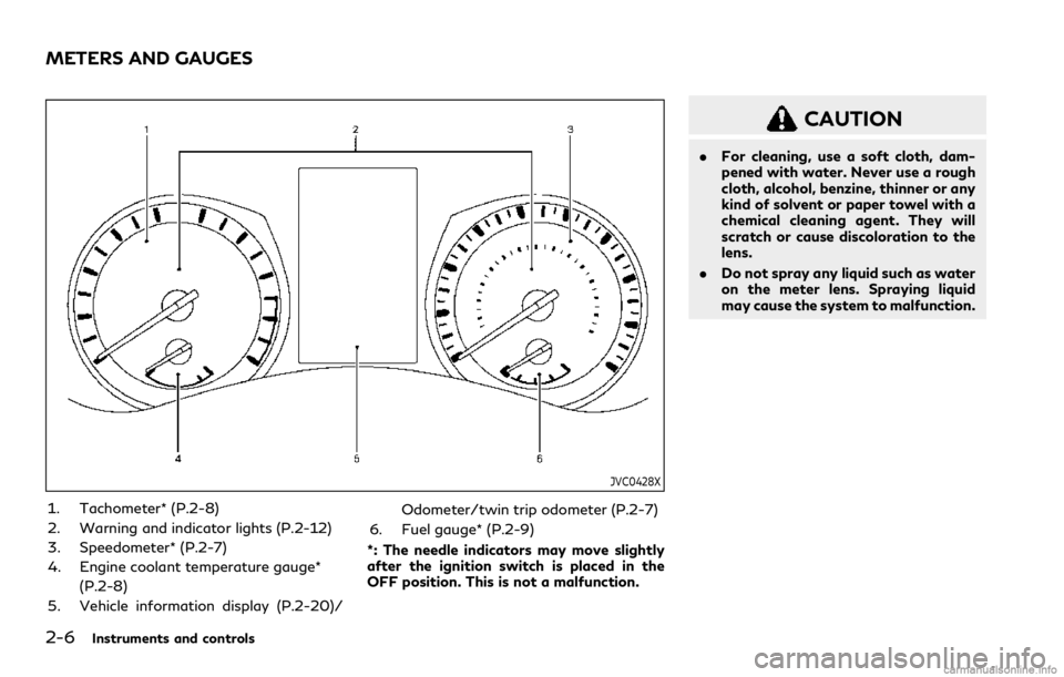
1. Tachometer* (P.2-8)
2. Warning and indicator lights (P.2-12)
3. Speedometer* (P.2-7)
4. Engine coolant temperature gauge*
(P.2-8)
5. Vehicle information display (P.2-20)/Odometer/twin trip odometer (P.2-7)
6. Fuel gauge* (P.2-9)
*: The needle indicators may move slightly
after the ignition switch is placed in the
OFF position. This is not a malfunction.
CAUTION
.For cleaning, use a soft cloth, dam-
pened with water. Never use a rough
cloth, alcohol, benzine, thinner or any
kind of solvent or paper towel with a
chemical cleaning agent. They will
scratch or cause discoloration to the
lens.
.Do not spray any liquid such as water
on the meter lens. Spraying liquid
may cause the system to malfunction.
METERS AND GAUGES
Page 85 of 492

JVI0636X
Speedometer
SPEEDOMETER AND OD-
OMETER
Speedometer
The speedometer indicates vehicle speed in
miles per hour (MPH) and kilometers per
hour (km/h).
JVI0637X
Odometer/twin trip odometer
Odometer/twin trip odometer
The odometerand twin trip odometerare displayed in the vehicle information
display when the ignition switch is in the
ON position.
The odometer records the total distance the
vehicle has been driven.
The twin trip odometer records the distance
of individual trips.Changing the display:
Pushing the TRIP RESET switch
under the
combination meter panel changes the dis-
play as follows:
TRIP A?TRIP B?TRIP A
Resetting the trip odometer:
Pushing the TRIP RESET switch
for more
than 1 second resets the trip odometer to
zero.
Instruments and controls2-7
Page 87 of 492
JVI0640X
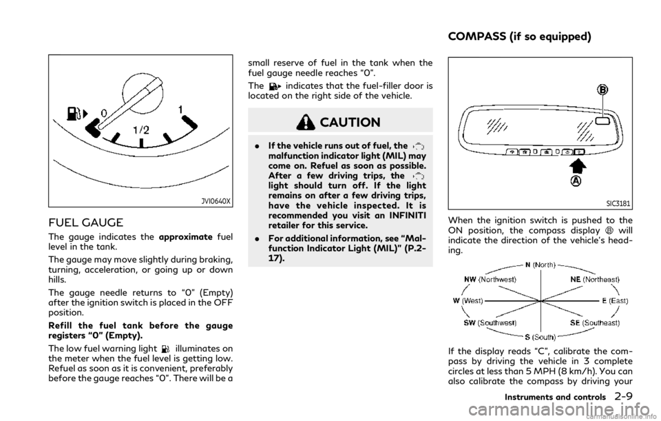
FUEL GAUGE
The gauge indicates theapproximatefuel
level in the tank.
The gauge may move slightly during braking,
turning, acceleration, or going up or down
hills.
The gauge needle returns to “0” (Empty)
after the ignition switch is placed in the OFF
position.
Refill the fuel tank before the gauge
registers “0” (Empty).
The low fuel warning light
illuminates on
the meter when the fuel level is getting low.
Refuel as soon as it is convenient, preferably
before the gauge reaches “0”. There will be asmall reserve of fuel in the tank when the
fuel gauge needle reaches “0”.
The
indicates that the fuel-filler door is
located on the right side of the vehicle.
CAUTION
.If the vehicle runs out of fuel, themalfunction indicator light (MIL) may
come on. Refuel as soon as possible.
After a few driving trips, the
light should turn off. If the light
remains on after a few driving trips,
have the vehicle inspected. It is
recommended you visit an INFINITI
retailer for this service.
.For additional information, see “Mal-
function Indicator Light (MIL)” (P.2-
17).
SIC3181
When the ignition switch is pushed to the
ON position, the compass displaywill
indicate the direction of the vehicle’s head-
ing.
If the display reads “C”, calibrate the com-
pass by driving the vehicle in 3 complete
circles at less than 5 MPH (8 km/h). You can
also calibrate the compass by driving your
Instruments and controls2-9
COMPASS (if so equipped)
Page 89 of 492
ZONE VARIATION CHANGE
PROCEDURE
The difference between magnetic north and
geographical north is known as variance. In
some areas, this difference can sometimes
be great enough to cause false compass
readings. Follow these instructions to set the
variance for your particular location if this
happens:
1. Push the
switch for more than 3
seconds. The current zone number will
appear in the display.
2. Find your current location and variance
number on the zone map.
3. Push the
switch repeatedly until the
new zone number appears in the display,
then release the switch. After you re-
lease the switch, the display will show a
compass direction within a few seconds.
.If the compass deviates from the
correct indication soon after repeated
adjustment, it is recommended you
have the compass checked at an
INFINITI retailer.
.The compass may not indicate the
correct compass point in tunnels or
while driving up or down a steep hill.
(The compass returns to the correct
compass point when the vehicle
moves to an area where the geomag-netism is stabilized.)
CAUTION
.Do not install a ski rack, antenna,
etc., which are attached to the vehi-
cle by means of a magnet. They affect
the operation of the compass.
.When cleaning the mirror, use a paper
towel or similar material dampened
with glass cleaner. Do not spray glass
cleaner directly on the mirror as it
may cause the liquid cleaner to enter
the mirror housing.
Instruments and controls2-11
Page 91 of 492
CHECKING LIGHTS
With all doors closed, apply the parking
brake, fasten the seat belts and place the
ignition switch in the ON position without
starting the engine. The following lights (if
so equipped) will come on:
,or,,,
The following lights (if so equipped) will
come on briefly and then go off:
,or,,,,
If any light does not come on or operates in a
way other than described, it may indicate a
burned-out bulb and/or a system malfunc-
tion. It is recommended you have the system
checked by an INFINITI retailer.
WARNING/INDICATOR LIGHTS
(red)
See “Vehicle information display” (P.2-20).
orBrake warning light
This light functions for both the parking
brake and the foot brake systems.
Parking brake indicator:
When the ignition switch is in the ON
position, the light comes on when the
parking brake is applied.Low brake fluid warning light:
When the ignition switch is in the ON
position, the light warns of a low brake fluid
level. If the light comes on while the engine is
running with the parking brake not applied,
stop the vehicle and perform the following:
1. Check the brake fluid level. If brake fluid
is necessary, add fluid and have the
system checked. It is recommended you
have this service performed by an
INFINITI retailer. (See “Brake fluid”
(P.8-9).)
2. If the brake fluid level is correct, have the
warning system checked. It is recom-
mended you have this service performed
by an INFINITI retailer.
Anti-lock Braking System (ABS) warning
indicator:
When the parking brake is released and the
brake fluid level is sufficient, if both the
brake warning light and the Anti-lock Brak-
ing System (ABS) warning light illuminate, it
may indicate the ABS is not functioning
properly. Have the brake system checked,
and if necessary repaired. It is recommended
you visit an INFINITI retailer for this service.
(See “Anti-lock Braking System (ABS) warn-
ing light” (P.2-15).)
WARNING
.Your brake system may not be work-
ing properly if the warning light is on.
Driving could be dangerous. If you
judge it to be safe, drive carefully to
the nearest service station for re-
pairs. Otherwise, have your vehicle
towed because driving it could be
dangerous.
.Pressing the brake pedal with the
engine stopped and/or low brake
fluid level may increase your stopping
distance and braking will require
greater pedal effort as well as pedal
travel.
.If the brake fluid level is below the
minimum or MIN mark on the brake
fluid reservoir, do not drive until the
brake system has been checked. It is
recommended you visit an INFINITI
retailer for this service.
Charge warning light
If the light comes on while the engine is
running, it may indicate the charging system
is not functioning properly. Turn the engine
off and check the alternator belt. If the belt is
loose, broken, missing or if the light remains
Instruments and controls2-13