engine INFINITI Q70 HYBRID 2014 Owner's Guide
[x] Cancel search | Manufacturer: INFINITI, Model Year: 2014, Model line: Q70 HYBRID, Model: INFINITI Q70 HYBRID 2014Pages: 522, PDF Size: 4.02 MB
Page 111 of 522
2-26Instruments and controls
pushed on. When the switch is pushed
again, the indicator disappears. While the
indicator is displayed, the DCA system is
operational. (See“Distance Control Assist
(DCA) system” (P.5-69).)
21. INFINITI Drive Mode Selector
indicator
When a driving mode is selected, the
selected mode indicator is displayed for
approximately 2 seconds.
.STANDARD
. SPORT
. ECO
. SNOW
(See “INFINITI drive mode selector” (P.5-
18).)
SIC4325
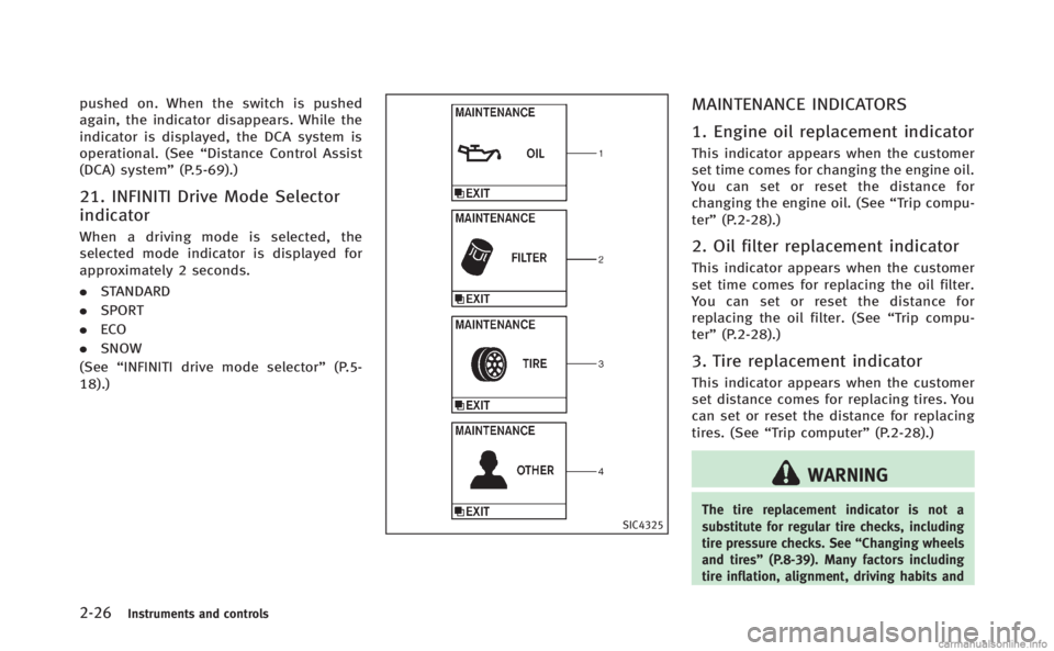
MAINTENANCE INDICATORS
1. Engine oil replacement indicator
This indicator appears when the customer
set time comes for changing the engine oil.
You can set or reset the distance for
changing the engine oil. (See “Trip compu-
ter” (P.2-28).)
2. Oil filter replacement indicator
This indicator appears when the customer
set time comes for replacing the oil filter.
You can set or reset the distance for
replacing the oil filter. (See “Trip compu-
ter” (P.2-28).)
3. Tire replacement indicator
This indicator appears when the customer
set distance comes for replacing tires. You
can set or reset the distance for replacing
tires. (See “Trip computer” (P.2-28).)
WARNING
The tire replacement indicator is not a
substitute for regular tire checks, including
tire pressure checks. See “Changing wheels
and tires” (P.8-39). Many factors including
tire inflation, alignment, driving habits and
Page 112 of 522
road conditions affect tire wear and when
tires should be replaced. Setting the tire
replacement indicator for a certain driving
distance does not mean your tires will last
that long. Use the tire replacement indicator
as a guide only and always perform regular
tire checks. Failure to perform regular tire
checks, including tire pressure checks could
result in tire failure. Serious vehicle damage
could occur and may lead to a collision,
which could result in serious personal injury
or death.
4.“OTHER” indicator
This indicator appears when the customer
set time comes for replacing items other
than the engine oil, oil filter and tires. You
can set or reset the distance for replacing
the items. (See “Trip computer” (P.2-28).)
More maintenance reminders are also
available on the center display. (See
“How to use INFO button” (P.4-10).)
JVI0203X
Instruments and controls2-27
Page 113 of 522
2-28Instruments and controls
SIC4327
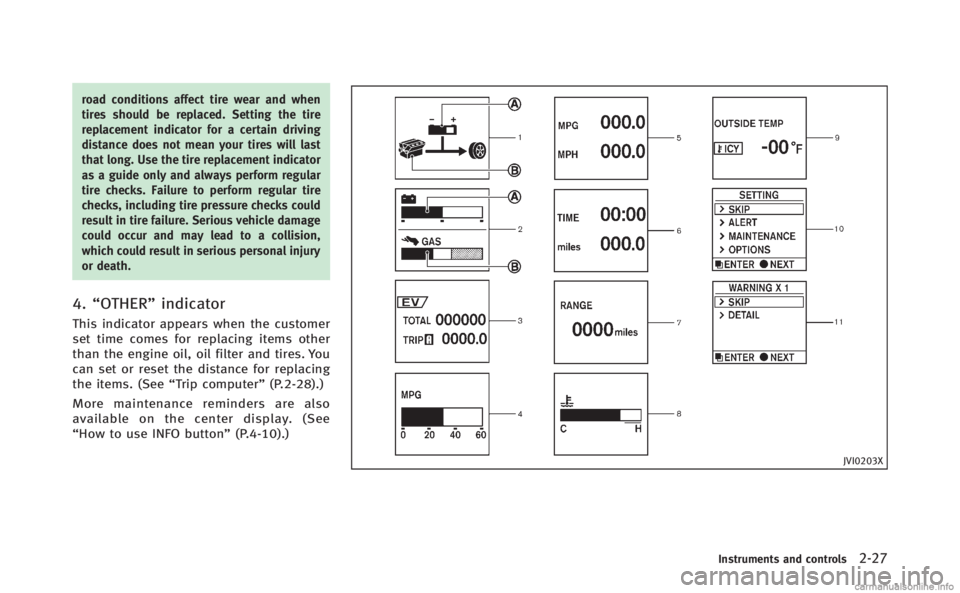
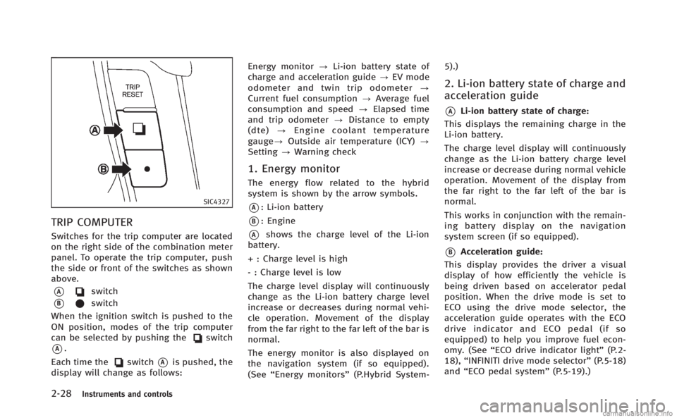
TRIP COMPUTER
Switches for the trip computer are located
on the right side of the combination meter
panel. To operate the trip computer, push
the side or front of the switches as shown
above.
*Aswitch
*Bswitch
When the ignition switch is pushed to the
ON position, modes of the trip computer
can be selected by pushing the
switch
*A.
Each time the
switch*Ais pushed, the
display will change as follows: Energy monitor
?Li-ion battery state of
charge and acceleration guide ?EV mode
odometer and twin trip odometer ?
Current fuel consumption ?Average fuel
consumption and speed ?Elapsed time
and trip odometer ?Distance to empty
(dte) ?Engine coolant temperature
gauge? Outside air temperature (ICY) ?
Setting ?Warning check
1. Energy monitor
The energy flow related to the hybrid
system is shown by the arrow symbols.
*A: Li-ion battery
*B: Engine
*Ashows the charge level of the Li-ion
battery.
+ : Charge level is high
- : Charge level is low
The charge level display will continuously
change as the Li-ion battery charge level
increase or decreases during normal vehi-
cle operation. Movement of the display
from the far right to the far left of the bar is
normal.
The energy monitor is also displayed on
the navigation system (if so equipped).
(See “Energy monitors” (P.Hybrid System- 5).)
2. Li-ion battery state of charge and
acceleration guide
*ALi-ion battery state of charge:
This displays the remaining charge in the
Li-ion battery.
The charge level display will continuously
change as the Li-ion battery charge level
increase or decrease during normal vehicle
operation. Movement of the display from
the far right to the far left of the bar is
normal.
This works in conjunction with the remain-
ing battery display on the navigation
system screen (if so equipped).
*BAcceleration guide:
This display provides the driver a visual
display of how efficiently the vehicle is
being driven based on accelerator pedal
position. When the drive mode is set to
ECO using the drive mode selector, the
acceleration guide operates with the ECO
drive indicator and ECO pedal (if so
equipped) to help you improve fuel econ-
omy. (See “ECO drive indicator light” (P.2-
18), “INFINITI drive mode selector” (P.5-18)
and “ECO pedal system” (P.5-19).)
Page 115 of 522
2-30Instruments and controls
last reset. Resetting is done by pushing theswitch*Bfor longer than 1 second.
(The average speed is also reset at the
same time.)
The display is updated every 30 seconds.
At about the first 1/3 mile (500 m) after a
reset, the display shows “——”.
Speed:
The average speed mode shows the
average vehicle speed since the last reset.
Resetting is done by pushing the
switch*Bfor longer than 1 second. (The
average fuel consumption is also reset at
the same time.)
The display is updated every 30 seconds.
The first 30 seconds after a reset, the
display shows “——”.
6. Elapsed time and trip odometer
(mls or km)
Elapsed time:
The elapsed time mode shows the time
since the last reset. The displayed time can
be reset by pushing the
switch*Bfor
longer than 1 second. (The trip odometer is
also reset at the same time.) Trip odometer:
The trip odometer mode shows the total
distance the vehicle has been driven since
the last reset. Resetting is done by pushing
the
switch*Bfor longer than 1
second. (The elapsed time is also reset at
the same time.)
7. Distance to empty (dte —mls or
km)
The distance to empty (dte) mode provides
you with an estimation of the distance that
can be driven before refueling. The dte is
constantly being calculated, based on the
amount of fuel in the fuel tank and the
actual fuel consumption.
The display is updated every 30 seconds.
The dte mode includes a low range warning
feature. If the fuel level is low, the warning
is displayed on the screen.
When the fuel level drops even lower, the
dte display will change to “——”.
. If the amount of fuel added is small, the
display just before the ignition switch
is pushed to the OFF position may
continue to be displayed.
. When driving uphill or rounding curves,
the fuel in the tank shifts, which may momentarily change the display.
8. Engine coolant temperature
gauge
The gauge indicates the engine coolant
temperature.
This displays the temperature of the
engine coolant. The range of coolant over-
heat is indicated by the horizontal line of
the upper part of the H mark.
The engine coolant temperature varies with
the outside air temperature and driving
conditions.
CAUTION
If the engine is overheated, continued
operation of the vehicle may seriously
damage the engine. See
“If your vehicle
overheats” (P.6-12) for immediate action
required.
9. Outside air temperature (ICY —8F
or 8C)
The outside air temperature is displayed in
8For 8C in the range of −22 to 1318F(−30
to 558C).
Page 116 of 522
The outside air temperature mode includes
a low temperature warning feature. If the
outside air temperature is below 378F
(38C), the warning is displayed on the
screen.
The outside temperature sensor is located
in front of the radiator. The sensor may be
affected by road or engine heat, wind
directions and other driving conditions.
The display may differ from the actual
outside temperature or the temperature
displayed on various signs or billboards.
10. Setting
Setting cannot be made while driving. A
message “Setting can only be operated
when stopped” is also displayed on the
dot matrix liquid crystal display.
The
switch*Aandswitch*Bare
used in the setting mode to select and
decide a menu.
SKIP:
Push the
switch*Ato move to the
warning check mode.
Push the
switch*Bto select other
menus. ALERT:
There are 3 submenus under the alert
menu.
.
BACK
Select this submenu to return to the top
page of the setting mode.
. TIMER
Select this submenu to specify when
the “TIMER” indicator activates.
. ICY
Select this submenu to display the low
outside temperature warning.
MAINTENANCE:
There are 5 submenus under the main-
tenance menu.
. BACK
Select this submenu to return to the top
page of the setting mode.
. OIL
Select this submenu to set or reset the
distance for changing the engine oil.
. FILTER
Select this submenu to set or reset the
distance for replacing the oil filter.
. TIRE
Select this submenu to set or reset the
distance for replacing tires. .
OTHER
Select this submenu and set or reset
the distance for replacing items other
than the engine oil, oil filter and tires.
OPTIONS: There are 4 submenus under the display
menu.
. BACK
Select this submenu to return to the top
page of the setting mode.
. LANGUAGE
Select this submenu to choose English
or French for display.
. UNIT
Select this submenu to choose the unit
from miles, MPG, 8F or km, l/100km,
8C.
. EFFECTS
Select this menu to set the dial effects
described below to on or off.
— The indicator needles sweep in the
meters when the hybrid system is
started.
Instruments and controls2-31
Page 145 of 522

2-60Instruments and controls
CAUTION
.Do not place objects (such as news-
papers, handkerchiefs, etc.) on the
sunshade inlet port. Doing so may
entangle these objects in the sunshade
when it is extending or retracting,
causing improper operation or damage
to the sunshade.
. Do not push the sunshade arm with your
hands, etc., as this may deform it.
Improper operation or damage to the
sunshade may result.
. Do not put any object into the sunshade
inlet port as this may result in improper
operation or damage the sunshade.
. Do not hang any object on the arm rail
as this may result in improper operation
or damage the sunshade.
. Do not forcefully pull the sunshade.
Doing so may elongate the sunshade.
Improper operation or damage to the
sunshade may result.
SIC4328
To activate or deactivate the welcome light
function, perform the following procedure.
1. Push the ignition switch to the ON
position.
2. Open the driver’s side door.
3. Within 20 seconds after the ignition switch is pushed to the ON position,
push the door open request switch on
the driver’s side door handle for more
than 5 seconds with the driver’s door
open.
4. A chime sounds when the setting is completed.
Once the welcome light function is active, the courtesy light
*Aand the passenger
cabin illumination will illuminate when you
approach the vehicle with the Intelligent
Key (within approximately 3.3 ft (1 m) of
the antenna built inside the door handles)
and the following conditions are met.
. All doors are closed and locked.
. The ignition switch is in the LOCK or OFF
position.
. The Intelligent Key is outside the
vehicle.
. The courtesy light operates within a set
duration.
In order to help maximize 12-volt battery
life, do not store the Intelligent Key within
the vehicle detection range.
BATTERY SAVER SYSTEM
The welcome light function will be deacti-
vated automatically to prevent 12-volt
battery discharge under the following
conditions.
. If the welcome light function does not
operate within a set duration. Note that
the duration is set to 9 days as the
factory default setting. To activate the
welcome light function again, start the
engine.
WELCOME LIGHT
Page 157 of 522

3-4Pre-driving checks and adjustments
WARNING
.Always have the doors locked while
driving. Along with the use of seat belts,
this provides greater safety in the event
of an accident by helping to prevent
persons from being thrown from the
vehicle. This also helps keep children
and others from unintentionally opening
the doors, and will help keep out
intruders.
. Before opening any door, always look for
and avoid oncoming traffic.
. Do not leave children unattended inside
the vehicle. They could unknowingly
activate switches or controls. Unat-
tended children could become involved
in serious accidents.
CAUTION
To prevent theft or accidents, be sure to stop
the engine and lock the doors before
stepping away from the vehicle.
SPA2527
LOCKING WITH MECHANICAL KEY
The power door lock system allows you to
lock or unlock all doors simultaneously
using the mechanical key.
.Turning the driver’s door key cylinder to
the front of the vehicle
*1will lock all
doors.
. Turning the driver’s door key cylinder
once to the rear of the vehicle
*2will
unlock the driver’s door. After returning
the key to the neutral position
*3,
turning it to the rear again within 60
seconds will unlock all doors. .
You can switch the lock system to the
mode that allows you to open all the
doors when the key is turned once.
(See “How to use SETTING button” (P.4-
16).)
OPENING AND CLOSING WINDOWS
WITH THE MECHANICAL KEY
The driver’s door key operation also allows
you to open and close the window that is
equipped with the automatic open/close
function. (See “Power windows” (P.2-55).)
To open the window, turn the driver’s door
key cylinder to the rear of the vehicle for
longer than 1 second. The door is unlocked
and the window keeps opening while
turning the key.
This function can also be performed by
pushing and holding the door UNLOCK
button of the Intelligent Key. (See “Remote
keyless entry system” (P.3-13).)
To close the window, turn the driver’s door
key cylinder to the front of the vehicle for
longer than 1 second. The door is locked
and the window keeps closing while turn-
ing the key.
DOORS
Page 169 of 522
3-16Pre-driving checks and adjustments
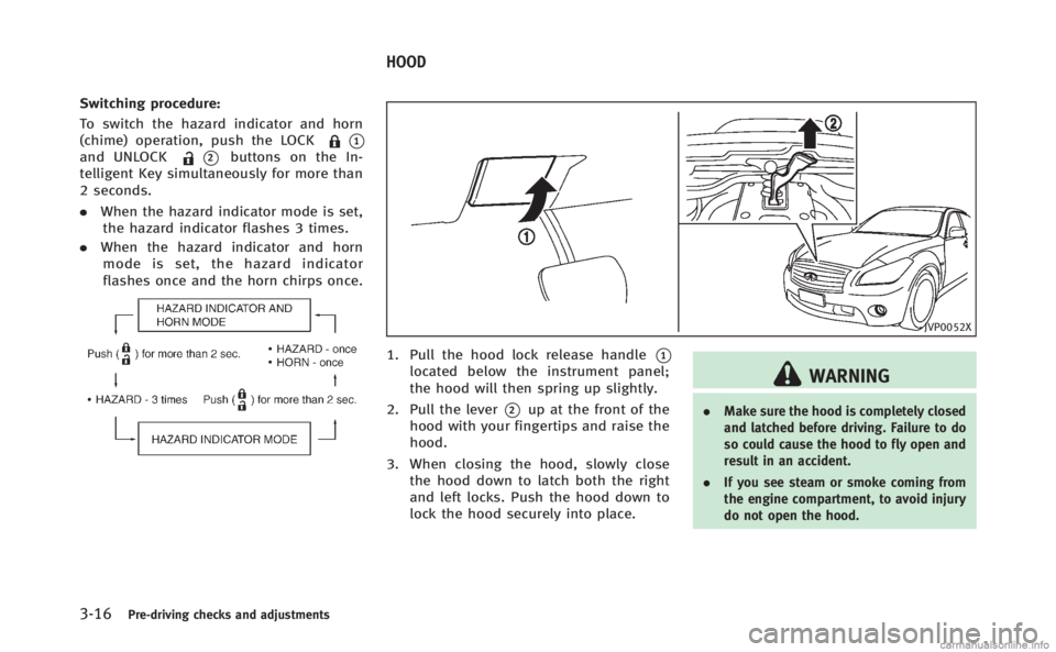
Switching procedure:
To switch the hazard indicator and horn
(chime) operation, push the LOCK
*1and UNLOCK*2buttons on the In-
telligent Key simultaneously for more than
2 seconds.
. When the hazard indicator mode is set,
the hazard indicator flashes 3 times.
. When the hazard indicator and horn
mode is set, the hazard indicator
flashes once and the horn chirps once.
JVP0052X
1. Pull the hood lock release handle*1located below the instrument panel;
the hood will then spring up slightly.
2. Pull the lever
*2up at the front of the
hood with your fingertips and raise the
hood.
3. When closing the hood, slowly close the hood down to latch both the right
and left locks. Push the hood down to
lock the hood securely into place.
WARNING
. Make sure the hood is completely closed
and latched before driving. Failure to do
so could cause the hood to fly open and
result in an accident.
. If you see steam or smoke coming from
the engine compartment, to avoid injury
do not open the hood.
HOOD
Page 188 of 522
SAA2954
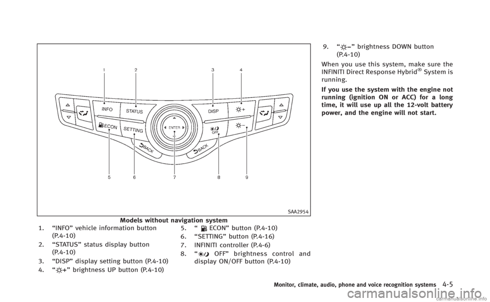
Models without navigation system
1. “INFO” vehicle information button
(P.4-10)
2. “STATUS” status display button
(P.4-10)
3. “DISP” display setting button (P.4-10)
4. “
”brightness UP button (P.4-10) 5.
“
ECON” button (P.4-10)
6. “SETTING” button (P.4-16)
7. INFINITI controller (P.4-6)
8. “
OFF” brightness control and
display ON/OFF button (P.4-10) 9.
“
”brightness DOWN button
(P.4-10)
When you use this system, make sure the
INFINITI Direct Response Hybrid
®System is
running.
If you use the system with the engine not
running (ignition ON or ACC) for a long
time, it will use up all the 12-volt battery
power, and the engine will not start.
Monitor, climate, audio, phone and voice recognition systems4-5
Page 197 of 522

4-14Monitor, climate, audio, phone and voice recognition systems
Maintenance information
The maintenance intervals can be dis-
played for the engine oil, oil filter, tire
and other reminders.
To set a maintenance interval, select a
preferred item from the list.
You can also set to display a message to
remind you that the maintenance needs to
be performed.
For models with the navigation system,
select the“Others” key to show the
“Maintenance” key.
The following example shows how to set
the engine oil maintenance information.
Use the same steps to set the other
maintenance information.
1. Set the interval (mileage) of the main- tenance schedule. To determine the
recommended maintenance interval,
refer to your “INFINITI Service and
Maintenance Guide”.
2. To display the reminder automatically when the desired distance is reached,
select the “Reminder” key.
3. Reset the driving distance to the new maintenance schedule. 4. To return to the previous screen, push
the BACK button.
The unit can be converted between “US”
and “Metric”. (See “How to use SETTING
button” (P.4-16).)
SAA3003
Models with navigation system
SAA1611
Models without navigation system