fuel cap INFINITI QX4 2001 Factory Service Manual
[x] Cancel search | Manufacturer: INFINITI, Model Year: 2001, Model line: QX4, Model: INFINITI QX4 2001Pages: 2395, PDF Size: 43.2 MB
Page 369 of 2395

SBR686C
Precautions
PRECAUTIONSNBAX0001IWhen installing rubber parts, final tightening must be car-
ried out under unladen condition* with tires on ground.
*Fuel, radiator coolant and engine oil full. Spare tire, jack,
hand tools and mats in designated positions.
IUse flare nut wrench when removing and installing brake
tubes.
IAfter installing removed suspension parts, check wheel
alignment and adjust if necessary.
IAlways torque brake lines when installing.
Preparation
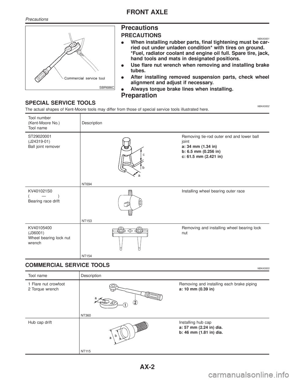
SPECIAL SERVICE TOOLSNBAX0002The actual shapes of Kent-Moore tools may differ from those of special service tools illustrated here.
Tool number
(Kent-Moore No.)
Tool nameDescription
ST29020001
(J24319-01)
Ball joint remover
NT694
Removing tie-rod outer end and lower ball
joint
a: 34 mm (1.34 in)
b: 6.5 mm (0.256 in)
c: 61.5 mm (2.421 in)
KV401021S0
(Ð)
Bearing race drift
NT153
Installing wheel bearing outer race
KV40105400
(J36001)
Wheel bearing lock nut
wrench
NT154
Removing and installing wheel bearing lock
nut
COMMERCIAL SERVICE TOOLSNBAX0003
Tool name Description
1 Flare nut crowfoot
2 Torque wrench
NT360
Removing and installing each brake piping
a: 10 mm (0.39 in)
Hub cap drift
NT115
Installing hub cap
a: 57 mm (2.24 in) dia.
b: 46 mm (1.81 in) dia.
FRONT AXLE
Precautions
AX-2
Page 503 of 2395

Removal and InstallationNBBT0010Front Door Trim
1. Remove inside handle escutcheon.
2. Remove power window switch, then disconnect the connectors.
3. Remove door armrest.
4. Remove bolts securing door finisher.
5. Pull on door finisher to remove clips from door panel and remove door finisher, then disconnect glass hatch
and fuel lid opener switch connector.
Rear Door Trim
6. Remove inside handle escutcheon.
7. Remove power window switch, then disconnect the connector.
8. Remove door armrest cap.
9. Remove bolts securing door finisher.
10. Pull on door finisher to remove clips from door panel and remove door finisher.
SBT696
DOOR TRIM
Removal and Installation
BT-30
Page 553 of 2395

Special Service ToolsNBEC0007The actual shapes of Kent-Moore tools may differ from those of special service tools illustrated here.
Tool number
(Kent-Moore No.)
Tool nameDescription
KV10117100
(J36471-A)
Front heated oxygen
sensor wrench
Rear heated oxygen
sensor wrench
NT379
Loosening or tightening front and rear heated oxy-
gen sensors with 22 mm (0.87 in) hexagon nut
(J44321)
Fuel pressure adapter
and gauge kit
SEF326Z
Checking fuel pressure with pressure gauge
Commercial Service ToolsNBEC0008
Tool name
(Kent-Moore No.)Description
Leak detector
(J41416)
NT703
Locating the EVAP leak
EVAP service port
adapter
(J41413-OBD)
NT704
Applying positive pressure through EVAP service
port
Fuel filler cap adapter
NT653
Checking fuel tank vacuum relief valve opening
pressure
PREPARATION
Special Service Tools
EC-18
Page 568 of 2395

operates, the flow rate of vapor controlled by EVAP canister purge volume control solenoid valve is propor-
tionally regulated as the air flow increases.
EVAP canister purge volume control solenoid valve also shuts off the vapor purge line during decelerating and
idling.
SEF428T
INSPECTIONNBEC0019EVAP CanisterNBEC0019S01Check EVAP canister as follows:
1. Pinch the fresh air hose.
2. Blow air into portAand check that it flows freely out of portB.
SEF231SB
Tightening TorqueNBEC0019S02Tighten EVAP canister as shown in the figure.
Make sure new O-ring is installed properly between EVAP can-
ister and EVAP canister vent control valve.
SEF427N
SEF943S
Fuel Tank Vacuum Relief Valve (Built into fuel filler cap)NBEC0019S031. Wipe clean valve housing.
2. Check valve opening pressure and vacuum.
Pressure:
15.3 - 20.0 kPa (0.156 - 0.204 kg/cm
2, 2.22 - 2.90 psi)
Vacuum:
þ6.0 to þ3.3 kPa (þ0.061 to þ0.034 kg/cm
2, þ0.87 to
þ0.48 psi)
3. If out of specification, replace fuel filler cap as an assembly.
CAUTION:
Use only a genuine fuel filler cap as a replacement. If an incor-
rect fuel filler cap is used, the MIL may come on.
GI
MA
EM
LC
FE
AT
TF
PD
AX
SU
BR
ST
RS
BT
HA
SC
EL
IDX
ENGINE AND EMISSION BASIC CONTROL SYSTEM DESCRIPTION
Evaporative Emission System (Cont'd)
EC-33
Page 575 of 2395

SEF328Z
3. Install pressure gauge to the fuel pressure check adapter as
shown in the figure.
4. Start engine and check for fuel leakage.
5. Read the indication of fuel pressure gauge.
At idling:
With vacuum hose connected
Approximately 235 kPa (2.4 kg/cm
2, 34 psi)
With vacuum hose disconnected
Approximately 294 kPa (3.0 kg/cm
2, 43 psi)
If results are unsatisfactory, perform Fuel Pressure Regulator
Check.
SEF329Z
Fuel Pressure Regulator CheckNBEC00251. Stop engine and disconnect fuel pressure regulator vacuum
hose from vacuum gallery.
2. Plug vacuum gallery with a blind cap.
3. Connect variable vacuum source to fuel pressure regulator.
SEF718BA
4. Start engine and read indication of fuel pressure gauge as
vacuum is changed.
Fuel pressure should decrease as vacuum increases. If results
are unsatisfactory, replace fuel pressure regulator.
BASIC SERVICE PROCEDURE
Fuel Pressure Check (Cont'd)
EC-40
Page 579 of 2395

IAir intake system
(Oil filler cap, oil level gauge, etc.)
IFuel pressure
IEngine compression
IThrottle valve
IEvaporative emission system
2) On air conditioner equipped models, checks should be carried out while the air conditioner is ªOFFº.
3) On automatic transmission equipped models, when checking idle rpm, ignition timing and mixture ratio,
checks should be carried out while shift lever is in ªNº position.
4) When measuring ªCOº percentage, insert probe more than 40 cm (15.7 in) into tail pipe.
5) Turn off headlamps, heater blower, rear defogger.
6) Keep front wheels pointed straight ahead.
7) Make the check after the cooling fan has stopped.
BASIC SERVICE PROCEDURE
Idle Speed/Ignition Timing/Idle Mixture Ratio Adjustment (Cont'd)
EC-44
Page 632 of 2395

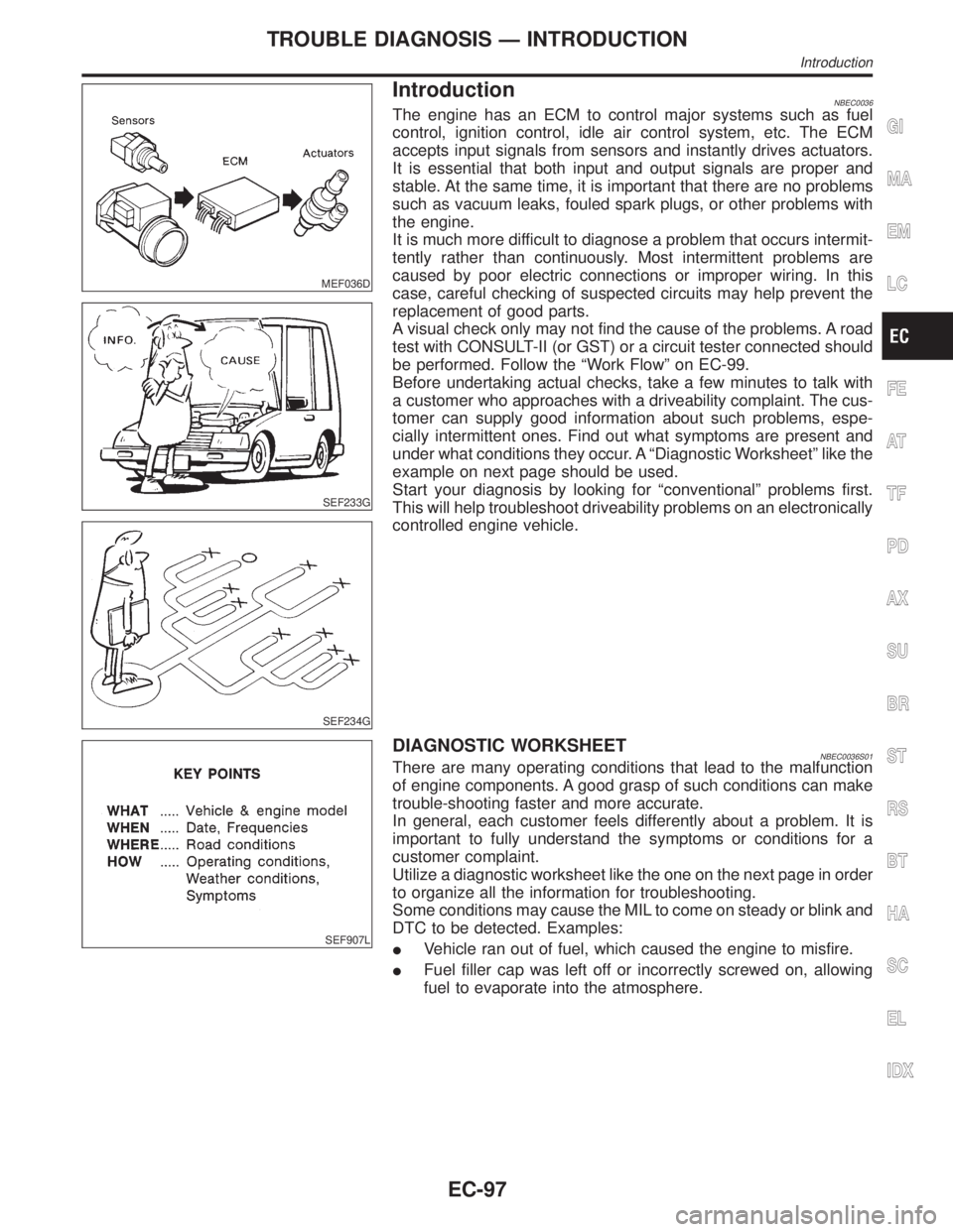
MEF036D
IntroductionNBEC0036
SEF233G
SEF234G
The engine has an ECM to control major systems such as fuel
control, ignition control, idle air control system, etc. The ECM
accepts input signals from sensors and instantly drives actuators.
It is essential that both input and output signals are proper and
stable. At the same time, it is important that there are no problems
such as vacuum leaks, fouled spark plugs, or other problems with
the engine.
It is much more difficult to diagnose a problem that occurs intermit-
tently rather than continuously. Most intermittent problems are
caused by poor electric connections or improper wiring. In this
case, careful checking of suspected circuits may help prevent the
replacement of good parts.
A visual check only may not find the cause of the problems. A road
test with CONSULT-II (or GST) or a circuit tester connected should
be performed. Follow the ªWork Flowº on EC-99.
Before undertaking actual checks, take a few minutes to talk with
a customer who approaches with a driveability complaint. The cus-
tomer can supply good information about such problems, espe-
cially intermittent ones. Find out what symptoms are present and
under what conditions they occur. A ªDiagnostic Worksheetº like the
example on next page should be used.
Start your diagnosis by looking for ªconventionalº problems first.
This will help troubleshoot driveability problems on an electronically
controlled engine vehicle.
SEF907L
DIAGNOSTIC WORKSHEETNBEC0036S01There are many operating conditions that lead to the malfunction
of engine components. A good grasp of such conditions can make
trouble-shooting faster and more accurate.
In general, each customer feels differently about a problem. It is
important to fully understand the symptoms or conditions for a
customer complaint.
Utilize a diagnostic worksheet like the one on the next page in order
to organize all the information for troubleshooting.
Some conditions may cause the MIL to come on steady or blink and
DTC to be detected. Examples:
IVehicle ran out of fuel, which caused the engine to misfire.
IFuel filler cap was left off or incorrectly screwed on, allowing
fuel to evaporate into the atmosphere.
GI
MA
EM
LC
FE
AT
TF
PD
AX
SU
BR
ST
RS
BT
HA
SC
EL
IDX
TROUBLE DIAGNOSIS Ð INTRODUCTION
Introduction
EC-97
Page 656 of 2395

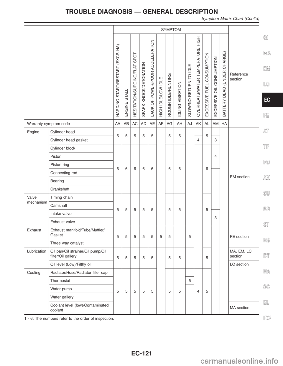
SYMPTOM
Reference
section
HARD/NO START/RESTART (EXCP. HA)
ENGINE STALL
HESITATION/SURGING/FLAT SPOT
SPARK KNOCK/DETONATION
LACK OF POWER/POOR ACCELERATION
HIGH IDLE/LOW IDLE
ROUGH IDLE/HUNTING
IDLING VIBRATION
SLOW/NO RETURN TO IDLE
OVERHEATS/WATER TEMPERATURE HIGH
EXCESSIVE FUEL CONSUMPTION
EXCESSIVE OIL CONSUMPTION
BATTERY DEAD (UNDER CHARGE)
Warranty symptom code AA AB AC AD AE AF AG AH AJ AK AL AM HA
Engine Cylinder head
55555 5 5 5
EM section Cylinder head gasket 4 3
Cylinder block
66666 6 6 64 Piston
Piston ring
Connecting rod
Bearing
Crankshaft
Valve
mechanismTiming chain
55555 5 5 5 Camshaft
Intake valve
3
Exhaust valve
Exhaust Exhaust manifold/Tube/Muffler/
Gasket
5555555 5 FEsection
Three way catalyst
Lubrication Oil pan/Oil strainer/Oil pump/Oil
filter/Oil gallery
55555 5 5 5MA, EM, LC
section
Oil level (Low)/Filthy oilLC section
Cooling Radiator/Hose/Radiator filler cap
55555 5 5 45 Thermostat 5
Water pump
Water gallery
Coolant level (low)/Contaminated
coolantMA section
1 - 6: The numbers refer to the order of inspection.
GI
MA
EM
LC
FE
AT
TF
PD
AX
SU
BR
ST
RS
BT
HA
SC
EL
IDX
TROUBLE DIAGNOSIS Ð GENERAL DESCRIPTION
Symptom Matrix Chart (Cont'd)
EC-121
Page 782 of 2395

SEF327R
Component DescriptionNBEC0130The heated oxygen sensor 2 (rear), after three way catalyst, moni-
tors the oxygen level in the exhaust gas on each bank.
Even if switching characteristics of the heated oxygen sensor 1
(front) are shifted, the air fuel ratio is controlled to stoichiometric,
by the signal from the heated oxygen sensor 2 (rear).
This sensor is made of ceramic zirconia. The zirconia generates
voltage from approximately 1V in richer conditions to 0V in leaner
conditions.
Under normal conditions the heated oxygen sensor 2 (rear) is not
used for engine control operation.
CONSULT-II Reference Value in Data Monitor
Mode
NBEC0131Specification data are reference values.
MONITOR ITEM CONDITION SPECIFICATION
HO2S2 (B1)
HO2S2 (B2)
IEngine: After warming upRevving engine from idle up to
2,000 rpm0 - 0.3V+,Approx. 0.6 - 1.0V
HO2S2 MNTR
(B1)
HO2S2 MNTR
(B2)LEAN+,RICH
ECM Terminals and Reference ValueNBEC0658Specification data are reference values and are measured between each terminal and ground.
CAUTION:
Do not use ECM ground terminals when measuring input/output voltage. Doing so may result in dam-
age to the ECM's transistor. Use a ground other than ECM terminals, such as the ground.
TERMI-
NAL
NO.WIRE
COLORITEM CONDITION DATA (DC Voltage)
72 ORHeated oxygen sensor
2 (rear) (bank 1)[Engine is running]
IWarm-up condition
IEngine speed is 2,000 rpm.0 - Approximately 1.0V
71 OR/LHeated oxygen sensor
2 (rear) (bank 2)[Engine is running]
IWarm-up condition
IEngine speed is 2,000 rpm.0 - Approximately 1.0V
SEF304UB
On Board Diagnosis LogicNBEC0133The heated oxygen sensor 2 (rear) has a much longer switching
time between rich and lean than the heated oxygen sensor 1
(front). The oxygen storage capacity before the three way catalyst
causes the longer switching time. To judge the malfunctions of
heated oxygen sensor 2 (rear), ECM monitors whether the mini-
mum voltage of sensor is sufficiently low during the various driving
condition such as fuel-cut.
Malfunction is detected when the minimum voltage from the sen-
sor is not reached to the specified voltage.
GI
MA
EM
LC
FE
AT
TF
PD
AX
SU
BR
ST
RS
BT
HA
SC
EL
IDX
DTC P0137, P0157 HEATED OXYGEN SENSOR 2 (REAR) (BANK 1)/(BANK 2)
(MIN. VOLTAGE MONITORING)
Component Description
EC-247
Page 792 of 2395

SEF327R
Component DescriptionNBEC0138The heated oxygen sensor 2 (rear), after three way catalyst, moni-
tors the oxygen level in the exhaust gas on each bank.
Even if switching characteristics of the heated oxygen sensor 1
(front) are shifted, the air fuel ratio is controlled to stoichiometric,
by the signal from the heated oxygen sensor 2 (rear).
This sensor is made of ceramic zirconia. The zirconia generates
voltage from approximately 1V in richer conditions to 0V in leaner
conditions.
Under normal conditions the heated oxygen sensor 2 (rear) is not
used for engine control operation.
CONSULT-II Reference Value in Data Monitor
Mode
NBEC0139Specification data are reference values.
MONITOR ITEM CONDITION SPECIFICATION
HO2S2 (B1)
HO2S2 (B2)
IEngine: After warming upRevving engine from idle up to
2,000 rpm0 - 0.3V+,Approx. 0.6 - 1.0V
HO2S2 MNTR
(B1)
HO2S2 MNTR
(B2)LEAN+,RICH
ECM Terminals and Reference ValueNBEC0659Specification data are reference values and are measured between each terminal and ground.
CAUTION:
Do not use ECM ground terminals when measuring input/output voltage. Doing so may result in dam-
age to the ECM's transistor. Use a ground other than ECM terminals, such as the ground.
TERMI-
NAL
NO.WIRE
COLORITEM CONDITION DATA (DC Voltage)
72 ORHeated oxygen sensor
2 (rear) (bank 1)[Engine is running]
IWarm-up condition
IEngine speed is 2,000 rpm.0 - Approximately 1.0V
71 OR/LHeated oxygen sensor
2 (rear) (bank 2)[Engine is running]
IWarm-up condition
IEngine speed is 2,000 rpm.0 - Approximately 1.0V
SEF303UB
On Board Diagnosis LogicNBEC0141The heated oxygen sensor 2 (rear) has a much longer switching
time between rich and lean than the heated oxygen sensor 1
(front). The oxygen storage capacity before the three way catalyst
causes the longer switching time. To judge the malfunctions of
heated oxygen sensor 2 (rear), ECM monitors whether the maxi-
mum voltage of the sensor is sufficiently high during the various
driving condition such as fuel-cut.
Malfunction is detected when the maximum voltage from the sen-
sor is not reached to the specified voltage.
GI
MA
EM
LC
FE
AT
TF
PD
AX
SU
BR
ST
RS
BT
HA
SC
EL
IDX
DTC P0138, P0158 HEATED OXYGEN SENSOR 2 (REAR) (BANK 1)/(BANK 2)
(MAX. VOLTAGE MONITORING)
Component Description
EC-257