steering wheel INFINITI QX50 2021 User Guide
[x] Cancel search | Manufacturer: INFINITI, Model Year: 2021, Model line: QX50, Model: INFINITI QX50 2021Pages: 542, PDF Size: 3.51 MB
Page 103 of 542

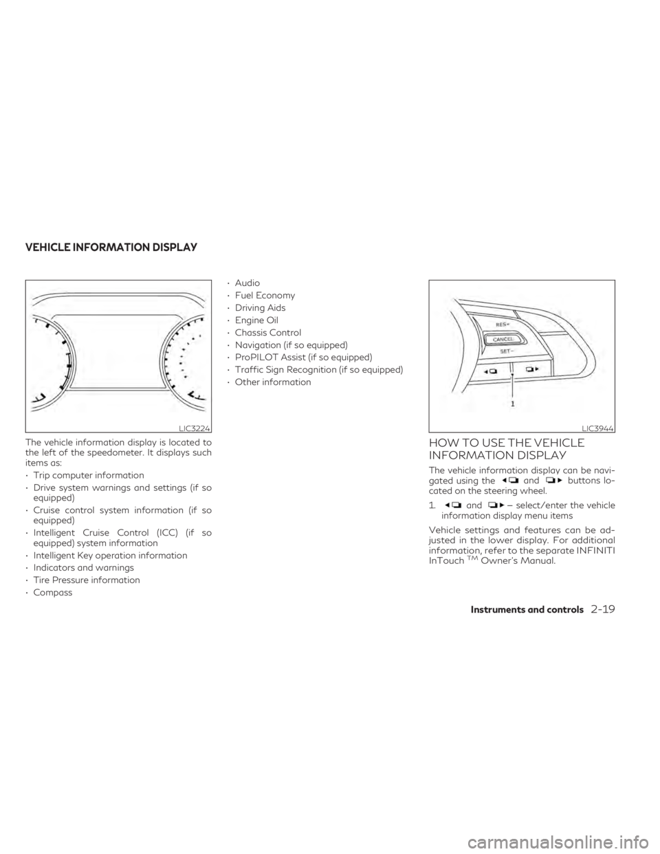
The vehicle information display is located to
the left of the speedometer. It displays such
items as:
• Trip computer information
• Drive system warnings and settings (if soequipped)
• Cruise control system information (if so equipped)
• Intelligent Cruise Control (ICC) (if so equipped) system information
• Intelligent Key operation information
• Indicators and warnings
• Tire Pressure information
• Compass • Audio
• Fuel Economy
• Driving Aids
• Engine Oil
• Chassis Control
• Navigation (if so equipped)
• ProPILOT Assist (if so equipped)
• Traffic Sign Recognition (if so equipped)
• Other informationHOW TO USE THE VEHICLE
INFORMATION DISPLAY
The vehicle information display can be navi-
gated using theandbuttons lo-
cated on the steering wheel.
1.
and— select/enter the vehicle
information display menu items
Vehicle settings and features can be ad-
justed in the lower display. For additional
information, refer to the separate INFINITI
InTouch
TMOwner’s Manual.
LIC3224LIC3944
VEHICLE INFORMATION DISPLAY
Instruments and controls2-19
Page 111 of 542

If one or more of these warning appears,
have the system checked. It is recommended
that you visit an INFINITI retailer for this
service.
Not Available Bad Weather
This message may appear when the Steering
Assist system is engaged.
Under the following condition, the Steering
Assist system is automatically canceled:
• When the wiper (HI) operates
The system will be available when the above
condition no longer exists.
Not Available: High Camera Temp
This message appears when the camera de-
tects an interior temperature of more than
104°F (40°C).
For additional information, see “Blind Spot
Intervention® (BSI)” (P. 5-54) , “Lane Depar-
ture Warning (LDW)” (P. 5-35), “Lane Depar-
ture Prevention (LDP)” (P. 5-40) or “Traffic
Sign Recognition (TSR)” (P. 5-32).
Not Available Poor Road Conditions
This message may appear when the ProPI-
LOT Assist system, the Blind Spot Interven-
tion® (BSI) system, the Lane Departure Pre-
vention (LDP) system or the Distance Control
Assist (DCA) system is engaged.Under the following conditions, the ProPI-
LOT Assist system, the Blind Spot Interven-
tion® (BSI) system, the Lane Departure Pre-
vention (LDP) system, or the Distance
Control Assist (DCA) system, is automatically
canceled:
• When the VDC operates
• When a wheel slips
The above system cannot be used in some
situations (VDC operates and wheel slips).
Not Available Seat Belt Not
Fastened
This message may appear when the Intelli-
gent Cruise Control (ICC) (with ProPILOT
Assist) system is engaged.
Under the following condition, the ICC (with
ProPILOT Assist) system is automatically
canceled:
• When the driver’s seat belt is not fastened
The above system cannot be used when the
driver’s seat belt is not fastened.
Not Available Visibility is Impaired
This message may appear when the Intelli-
gent Cruise Control (ICC) (with ProPILOT
Assist) system is engaged.
Under the following conditions, The ICC
(with ProPILOT Assist) system is automati-
cally canceled:
• The camera area of the windshield is
fogged up or covered with dirt, water
drops, ice, snow, etc.
• Strong light, such as sunlight or high beams from oncoming vehicles, enter the front
camera
The system will be available when the above
conditions no longer exist.
If the warning message continues to appear,
stop the vehicle in a safe location, turn the
engine off, and clean the windshield.
ProPILOT Assist indicators
These indicators show the ProPILOT Assist
system status.
For additional information, see “ProPILOT
Assist” (P. 5-77).
Rear Automatic Braking
(RAB) indicator
This indicator appears to indicate the status
of the Rear Automatic Braking (RAB) system.
For additional information, see “Rear Auto-
matic Braking (RAB)” (P. 5-119).
Instruments and controls2-27
Page 112 of 542

Speed Limit Sign indicator
This message may appear when the Traffic
Sign Recognition system is engaged.
For additional information, see “Traffic Sign
Recognition (TSR)” (P. 5-32).
Steering Assist Alert
This message may appear when the Steering
Assist system is engaged.
It will be displayed under the following
condition:
• When not holding the steering wheel orwhen there is no steering wheel operation
Please hold on the steering wheel immedi-
ately. When the steering operation is de-
tected, the warning turns off and the steering
assist function is automatically restored.
Steering Assist Not Available:
Cannot Detect Lane
This message may appear when the Steering
Assist system is engaged.
Under the following conditions, the Steering
Assist system is automatically canceled: • When lane markers in the traveling lane
cannot be correctly detected for a period of
time due to such items as a snow rut, re-
flection of light on a rainy day or several
unclear lane markers are present
If you want to use the Steering Assist system
again, cancel the ProPILOT Assist system
and set it again when lane markers are clearly
visible.
Steering Assist status
This indicator appears when the Steering As-
sist system is engaged.
For additional information, see “ProPILOT
Assist” (P. 5-77).
System fault See Owner’s Manual
This warning appears if there is a malfunction
in the Rear Automatic Braking (RAB) system.
For additional information, see “Rear Auto-
matic Braking (RAB)” (P. 5-119).
Unavailable: Front Radar Blocked
This message appears when the Distance
Control Assist (DCA), Forward Emergency
Braking (FEB) with Pedestrian Detection, or
Predictive Forward Collision Warning
(PFCW) systems become unavailable be-
cause the front radar is obstructed. For addi-
tional information, see “Distance Control As-
sist (DCA)” (P. 5-106), “Forward Emergency
Braking (FEB) with Pedestrian Detection”
(P. 5-123), or “Predictive Forward Collision
Warning (PFCW)” (P. 5-133).
Unavailable: Side Radar Obstruction
This message appears when one of the fol-
lowing systems (if so equipped) becomes un-
available because a radar blockage is de-
tected.
• Blind Spot Intervention® (BSI)
• Blind Spot Warning (BSW)
• Rear Cross Traffic Alert (RCTA)
For additional information, see “Starting and
driving” (P. 5-4).
2-28Instruments and controls
Page 124 of 542

Adaptive Front lighting System
(AFS) (if so equipped)
The Adaptive Front lighting System (AFS) will
automatically adjust the headlights (low
beam) toward the turning direction to im-
prove the driver’s view. When the headlight
switch is ON and the driver operates the
steering wheel in a turn, the AFS system will
be activated.
The AFS will operate:
• when the headlight switch is ON.
• when the shift lever is in any position otherthan P (Park) or R (Reverse).
• when the vehicle is driven at above 16 mph (25 km/h) for the left-side headlight. Note
that the right-side low beam headlight will
swivel but the left side will not swivel when
the vehicle is at a stop and the steering
wheel is turned. The vehicle must attain a
speed above 16 mph (25 km/h) before AFS
activates the left-side headlight.
AFS will also adjust the headlight to a proper
axis automatically, depending on the number
of occupants in the vehicle, the load the ve-
hicle is carrying and the road conditions. If the AFS OFF indicator blinks or the vehicle
information display shows an AFS system
error message after the ignition switch has
been pushed to the ON position, this may
indicate that the AFS is not functioning prop-
erly. Have the system checked. It is recom-
mended you visit an INFINITI retailer for this
service. When the engine is started, the head-
lights will vibrate to check the system condi-
tion. This is not a malfunction.
Automatic headlight aiming control
(if so equipped)
Your vehicle is equipped with an automatic
headlight levelling system. The headlight axis
is controlled automatically.
INFINITI recommends that you consult the
local regulations on the use of lights.
LED DAYTIME RUNNING LIGHTS
(DRL) SYSTEM
The LED portion of the headlights automati-
cally illuminate at 100% intensity when the
engine is started and the parking brake re-
leased. The LED Daytime Running Lights
(DRL) system operates with the headlight
switch in the OFF position. When you turn
the headlight switch to the
position for
full illumination, the LED lights switch from
LED DRL system to the park function. If the parking brake is applied before the
engine is started, the LED DRL system does
not illuminate. The LED DRL system illumi-
nates when the parking brake is released. The
LED DRL system will remain on until the
ignition switch is placed in the OFF position.
It is necessary at dusk to turn the headlight
switch on for interior controls and switches
to illuminate, as those remain off while the
switch is in the OFF position.
WARNING
When the LED DRL system is active, tail
lights on your vehicle are not on. It is nec-
essary at dusk to turn on your headlights.
Failure to do so could cause an accident
injuring yourself and others.
2-40Instruments and controls
Page 126 of 542

FOG LIGHT SWITCH (if so
equipped)
To turn the fog lights on, turn the headlight
switch to theposition, then push the fog
light switch on.
To turn the fog lights on with the headlight
switch in the AUTO position, the headlights
must be on, then push the fog light switch on.
To turn the fog lights off, push the fog light
switch again.
The headlights must be on and the low beams
selected for the fog lights to operate. The fog
lights automatically turn off when the high
beam headlights are selected. To sound the horn, push near the horn icon on
the steering wheel.WARNING
Do not disassemble the horn. Doing so
could affect proper operation of the
supplemental front air bag system. Tam-
pering with the supplemental front air bag
system may result in serious personal
injury.
WARNING
Do not use or allow occupants to use the
climate controlled seats if you or the occu-
pants cannot monitor seat temperatures
or have an inability to feel pain in those
body parts in contact with the seat. Use of
the climate controlled seats by such people
could result in serious injury.
LIC3824LIC4311LIC3905
HORN CLIMATE CONTROLLED SEAT
SWITCHES (if so equipped)
2-42Instruments and controls
Page 160 of 542

3 Pre-driving checks and adjustments
Keys.............................................3-2
INFINITI Intelligent Key .......................3-2
INFINITI Vehicle Immobilizer System
keys ..........................................3-4
Doors ...........................................3-4
Locking with key ..............................3-4
Locking with inside lock knob Type A
(if so equipped) ...............................3-5
Locking with inside lock knob Type B
(if so equipped) ...............................3-5
Locking with power door lock switch ..........3-5
Automatic door locks .........................3-6
Child safety rear door lock .....................3-6
INFINITI Intelligent Key System ...................3-6
Operating range ..............................3-8
Door locks/unlocks precaution ................3-9
INFINITI Intelligent Key operation .............3-9
How to use the remote keyless entry
function .................................... 3-13
Warning signals ............................. 3-16
Troubleshooting guide ......................3-16
Log-in function ............................. 3-18
Remote Engine Start (if so equipped) ...........3-18
Remote Engine Start operating range ........3-19
Remote starting the vehicle ..................3-19
Extending engine run time ...................3-19
Canceling a Remote Engine Start ............3-20 Conditions the Remote Engine Start will
not work
................................... 3-20
Hood .......................................... 3-21
Liftgate ....................................... 3-21
Operating the power liftgate ................3-22
Motion-Activated Liftgate
(if so equipped) ............................. 3-24
Power liftgate main switch ..................3-26
Liftgate release ............................. 3-26
Liftgate position setting .....................3-27
Fuel-filler door ................................. 3-28
Opening the fuel-filler door ..................3-28
Fuel-filler cap ............................... 3-28
Steering wheel ................................. 3-31
Manual operation (if so equipped) ...........3-31
Automatic operation (if so equipped) .........3-31
Sun visors ..................................... 3-32
Vanity mirrors .............................. 3-33
C
ard holder ................................. 3-33
Mirrors ........................................ 3-33
Manual anti-glare rearview mirror
(if so equipped) ............................. 3-33
Automatic anti-glare rearview mirror
(if so equipped) ............................. 3-34
Outside mirrors ............................. 3-34
Memory Seat (if so equipped) ...................3-36
Page 190 of 542

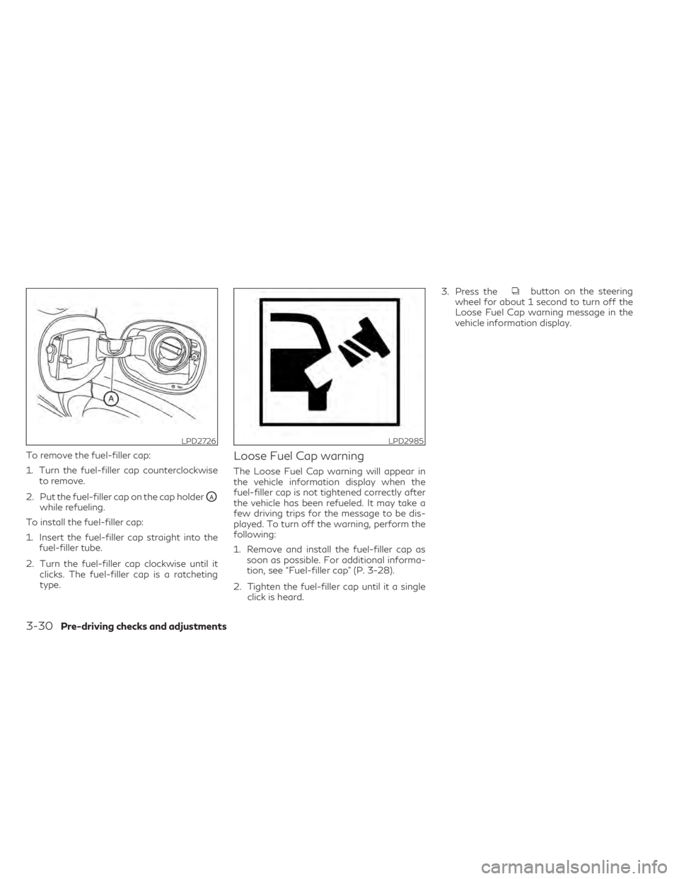
To remove the fuel-filler cap:
1. Turn the fuel-filler cap counterclockwiseto remove.
2. Put the fuel-filler cap on the cap holder
OAwhile refueling.
To install the fuel-filler cap:
1. Insert the fuel-filler cap straight into the fuel-filler tube.
2. Turn the fuel-filler cap clockwise until it clicks. The fuel-filler cap is a ratcheting
type.
Loose Fuel Cap warning
The Loose Fuel Cap warning will appear in
the vehicle information display when the
fuel-filler cap is not tightened correctly after
the vehicle has been refueled. It may take a
few driving trips for the message to be dis-
played. To turn off the warning, perform the
following:
1. Remove and install the fuel-filler cap assoon as possible. For additional informa-
tion, see “Fuel-filler cap” (P. 3-28).
2. Tighten the fuel-filler cap until it a single click is heard. 3. Press the
button on the steering
wheel for about 1 second to turn off the
Loose Fuel Cap warning message in the
vehicle information display.
LPD2726LPD2985
3-30Pre-driving checks and adjustments
Page 191 of 542

WARNING
• Do not adjust the steering wheel while
driving. You could lose control of your
vehicle and cause an accident.
• Do not adjust the steering wheel any
closer to you than is necessary for proper
steering operation and comfort. The
driver's air bag inflates with great force.
If you are unrestrained, leaning forward,
sitting sideways or out of position in any
way, you are at greater risk of injury or
death in a crash. You may also receive
serious or fatal injuries from the air bag if
you are up against it when it inflates.
Always sit back against the seatback and
as far away as practical from the steer-
ing wheel. Always use the seat belts.
MANUAL OPERATION (if so
equipped)
Tilt and telescopic operation
Push the lock leverO1down:
• Adjust the steering wheel up or down in direction
O2to the desired position.
• Adjust the steering wheel forward or back- ward in direction
O3to the desired position.
Pull the lock lever
O1up firmly to lock the
steering wheel in place.
AUTOMATIC OPERATION (if so
equipped)
Tilt and telescopic operation
To adjust the steering wheel move the switch
O1in the following directions:
• Adjust the steering wheel up or down in direction
O2to the desired tilt position.
• Adjust the steering wheel forward or back- ward in direction
O3to the desired tele-
scopic position.
LPD2728LPD2752
STEERING WHEEL
Pre-driving checks and adjustments3-31
Page 192 of 542

Entry/Exit function (if so equipped)
The memory seat system will make the steer-
ing wheel move up automatically when the
driver's door is opened and the ignition switch
is in the LOCK position. This lets the driver get
into and out of the seat more easily. The
steering wheel moves back into position
when the driver's door is closed and the igni-
tion switch is pushed.
For additional information, see “Memory
seat” (P. 3-36).1. To block glare from the front, swing down
the sun visorO1.
2. To block glare from the side, remove the sun visor from the center mount and
swing the visor to the side
O2.
3. Slide the extension
O3sun visor in or out
as needed.
CAUTION
• Do not store the sun visor before return-
ing the extension to its original position.
• Do not pull the extension sun visor forc-
ibly downward.
WPD0344
SUN VISORS
3-32Pre-driving checks and adjustments
Page 196 of 542

The memory seat system has two features:
• Memory storage function
• Entry/exit function
MEMORY STORAGE FUNCTION
Two positions for the driver's seat, steering
column, and outside mirrors can be stored in
the memory seat. Follow these procedures to
set the memory system.
NOTE:
The vehicle should be stopped while setting
the memory.
1. Adjust the driver's seat, steering column,and outside mirrors to the desired posi-
tions by manually operating each adjust-
ing switch. For additional information, see
“Seats” (P. 1-2), “Steering wheel” (P. 3-31)
and “Outside mirrors” (P. 3-34). 2. Push the SET switch and, within 5 sec-
onds, push the memory switch (1 or 2).
The indicator light for the pushed memory
switch will come on and stay on for ap-
proximately 5 seconds.
The chime will sound when the memory is
stored.
NOTE:
If a new memory position is stored in the
same memory switch, the previous memory
position will be overwritten by the new
stored position.
Confirming memory storage
• Push the SET switch.
• If a memory position has been stored in the switch (1 or 2) then the indicator light for
the respective switch will stay on for ap-
proximately 5 seconds.
LPD2729
MEMORY SEAT (if so equipped)
3-36Pre-driving checks and adjustments