window INFINITI QX50 2021 Owner's Guide
[x] Cancel search | Manufacturer: INFINITI, Model Year: 2021, Model line: QX50, Model: INFINITI QX50 2021Pages: 542, PDF Size: 3.51 MB
Page 201 of 542
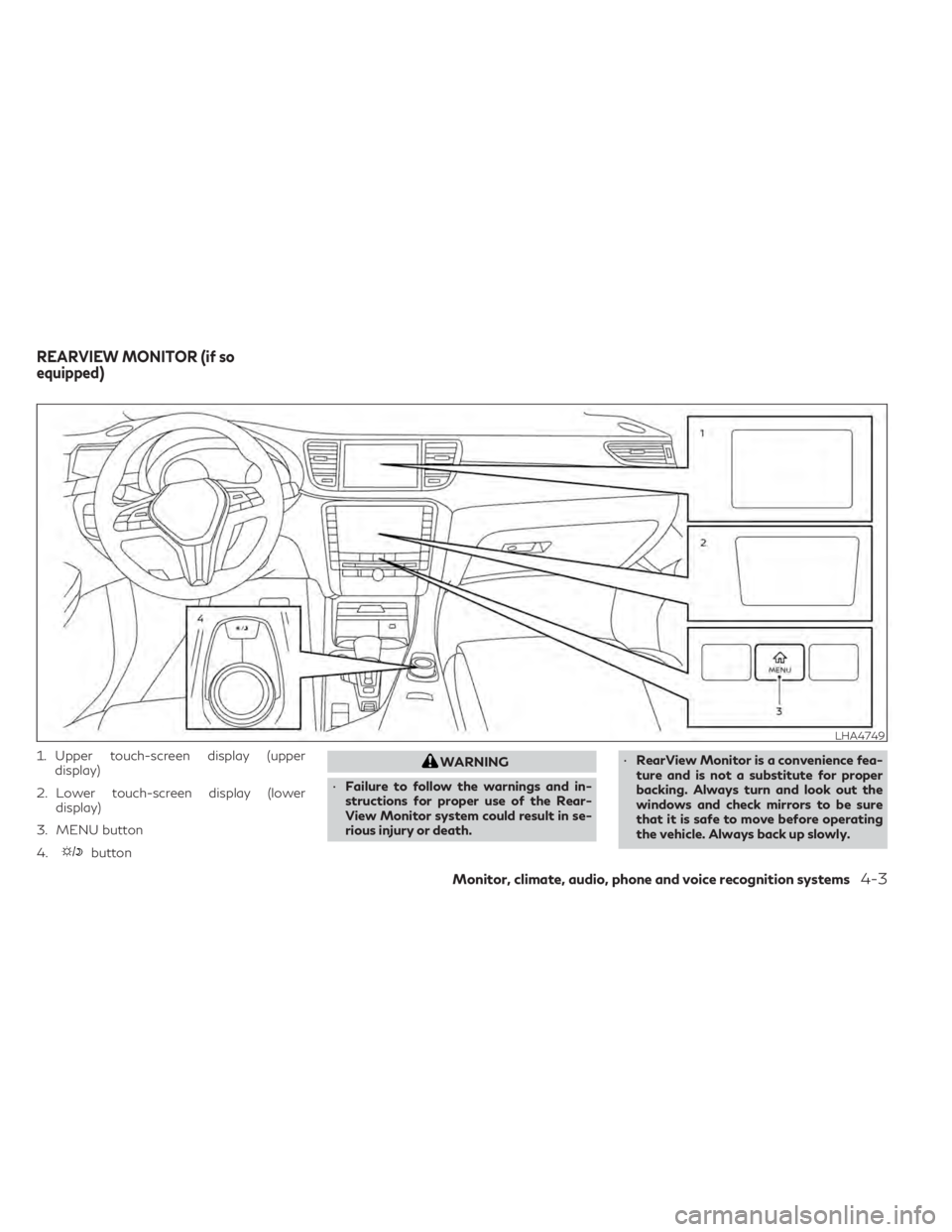
1. Upper touch-screen display (upperdisplay)
2. Lower touch-screen display (lower display)
3. MENU button
4.
button
WARNING
• Failure to follow the warnings and in-
structions for proper use of the Rear-
View Monitor system could result in se-
rious injury or death. •
RearView Monitor is a convenience fea-
ture and is not a substitute for proper
backing. Always turn and look out the
windows and check mirrors to be sure
that it is safe to move before operating
the vehicle. Always back up slowly.
LHA4749
REARVIEW MONITOR (if so
equipped)
Monitor, climate, audio, phone and voice recognition systems4-3
Page 225 of 542

•The system will not detect small objects
below the bumper, and may not detect
objects close to the bumper or on the
ground.
• The system may not detect the following
objects:
– Fluffy objects such as snow, cloth,
cotton, grass or wool.
– Thin objects such as rope, wire or
chain.
– Wedge-shaped objects.
• If your vehicle sustains damage to the
bumper fascia, leaving it misaligned or
bent, the sensing zone may be altered
causing inaccurate measurement of ob-
jects or false alarms.
CAUTION
Excessive noise (such as audio system vol-
ume or an open vehicle window) will inter-
fere with the tone and it may not be heard.
System temporarily unavailable
When the amber markers are displayed at the
corners of the vehicle icon and the function
cannot be activated from the Camera setting
menu (the setting items are grayed out), the
sonar system may be malfunctioning.
SYSTEM MAINTENANCE
CAUTION
Keep the surface of the sonar sensors (lo-
cated on the front and rear bumper fascia)
free from accumulations of snow, ice and
dirt. Do not scratch the surface of the sonar
sensors when cleaning. If the sensors are
covered, the accuracy of the sonar function
will be diminished.
Monitor, climate, audio, phone and voice recognition systems4-27
Page 229 of 542
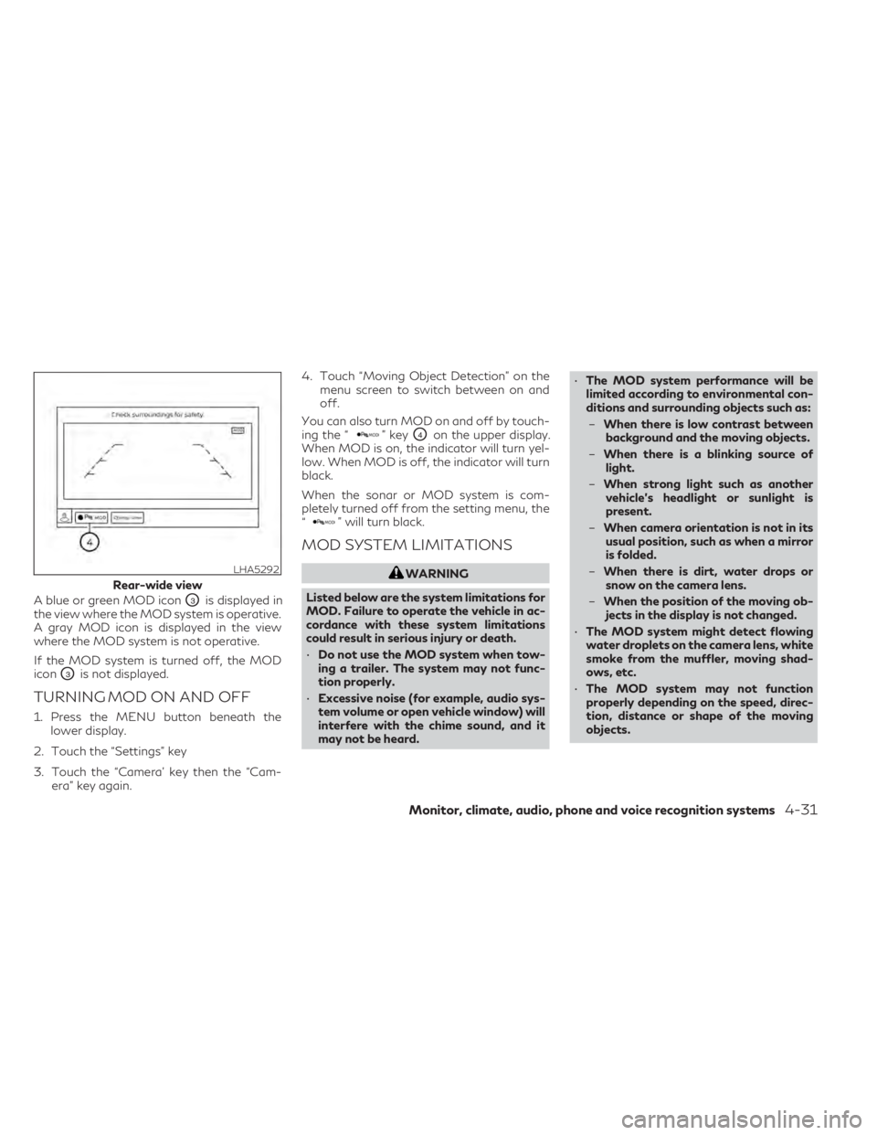
A blue or green MOD iconO3is displayed in
the view where the MOD system is operative.
A gray MOD icon is displayed in the view
where the MOD system is not operative.
If the MOD system is turned off, the MOD
icon
O3is not displayed.
TURNING MOD ON AND OFF
1. Press the MENU button beneath the lower display.
2. Touch the “Settings” key
3. Touch the “Camera’ key then the “Cam- era” key again. 4. Touch “Moving Object Detection” on the
menu screen to switch between on and
off.
You can also turn MOD on and off by touch-
ing the “
” keyO4on the upper display.
When MOD is on, the indicator will turn yel-
low. When MOD is off, the indicator will turn
black.
When the sonar or MOD system is com-
pletely turned off from the setting menu, the
“
” will turn black.
MOD SYSTEM LIMITATIONS
WARNING
Listed below are the system limitations for
MOD. Failure to operate the vehicle in ac-
cordance with these system limitations
could result in serious injury or death.
• Do not use the MOD system when tow-
ing a trailer. The system may not func-
tion properly.
• Excessive noise (for example, audio sys-
tem volume or open vehicle window) will
interfere with the chime sound, and it
may not be heard. •
The MOD system performance will be
limited according to environmental con-
ditions and surrounding objects such as:
– When there is low contrast between
background and the moving objects.
– When there is a blinking source of
light.
– When strong light such as another
vehicle’s headlight or sunlight is
present.
– When camera orientation is not in its
usual position, such as when a mirror
is folded.
– When there is dirt, water drops or
snow on the camera lens.
– When the position of the moving ob-
jects in the display is not changed.
• The MOD system might detect flowing
water droplets on the camera lens, white
smoke from the muffler, moving shad-
ows, etc.
• The MOD system may not function
properly depending on the speed, direc-
tion, distance or shape of the moving
objects.LHA5292
Rear-wide view
Monitor, climate, audio, phone and voice recognition systems4-31
Page 232 of 542

1. Lower touch-screen display (lower display)
2.Temperature control increase button
(passenger’s side)
3.
Temperature control decrease button
(passenger’s side)
4.
Air recirculation button
5.Front defroster button 6.
Rear window and outside mirror (if so
equipped) defroster switch
7. ON-OFF button
8.
CLIMATE button
9.MENU button
10.Manual air flow control button
11.Fan speed decrease button
12.Fan speed increase button 13.AUTO button
14.
Temperature control decrease button
(driver’s side)
15.
Temperature control increase button
(driver’s side)
WARNING
• The air conditioner cooling function op-
erates only when the engine is running.
• Do not leave children or adults who
would normally require the assistance of
others alone in your vehicle. Pets should
also not be left alone. They could acci-
dentally injure themselves or others
through inadvertent operation of the
vehicle. Also, on hot, sunny days, tem-
peratures in a closed vehicle could
quickly become high enough to cause se-
vere or possibly fatal injuries to people or
animals.
• Do not use the recirculation mode for
long periods as it may cause the interior
air to become stale and the windows to
fog up.
Start the engine and operate the controls to
activate the air conditioner.
LHA4574
HEATER AND AIR CONDITIONER
(automatic)
4-34Monitor, climate, audio, phone and voice recognition systems
Page 233 of 542
NOTE:
• Odors from inside and outside the vehiclecan build up in the air conditioner unit.
Odor can enter the passenger compart-
ment through the vents.
• When parking, set the heater and air con- ditioner controls to turn off air recircula-
tion to allow fresh air into the passenger
compartment. This should help reduce
odors inside the vehicle
AUTOMATIC OPERATION
Press the AUTO button to set the automatic
control mode that keeps the air distribution,
temperature and the fan speed automatically.
Cooling and/or dehumidified
heating (AUTO)
This mode may be used all year round as the
system automatically works to keep a con-
stant temperature. Air flow distribution, air
intake control, and fan speed are also con-
trolled automatically.
1. Press the
CLIMATE button on the
lower display menu. The CLIMATE screen
will display on the lower display.
2. Press the AUTO button on. (The indicator on the button will illuminate and AUTO
will be displayed on the CLIMATE screen.) 3. Press the
temperature control
buttons on the driver’s side to set the de-
sired temperature.
• The temperature of the passenger com- partment will be maintained automatically.
Air flow distribution, air intake control and
fan speed are also controlled automatically.
• A visible mist may be seen coming from the vents in hot, humid conditions as the air is
cooled rapidly. This does not indicate a
malfunction.
Dehumidified defrosting or
defogging
1. Press thefront defroster button on.
(The indicator light on the button will
come on.)
2. Operate the
temperature con-
trol buttons to set the desired
temperature.
• To quickly remove ice from the outside of the windows, use the
fan speed con-
trol button or the “” key to set the fan
speed to maximum.
• As soon as possible after the windshield is clean, press the AUTO button to return to
the automatic mode. • When the
front defroster button is
pressed, the air conditioner will automati-
cally be turned on at outside temperatures
approximately 32°F (0°C) to defog the
windshield. The air recirculate mode auto-
matically turns off, allowing outside air to
be drawn into the passenger compartment
to further improve the defogging
performance.
Remote Engine Start with
Intelligent Climate Control (if so
equipped)
Vehicles equipped with automatic climate
controls and Remote Engine Start function
may go into automatic heating or cooling
mode when Remote Engine Start is activated
depending on outside and cabin tempera-
tures. During this period, the climate control
display and buttons will be inoperable until
the ignition switch is turned on. In Remote
Engine Start defrosting mode, the rear win-
dow defroster, heated seat (if so equipped)
and heated steering wheel (if so equipped)
may be activated automatically. In Remote
Engine Start cooling mode, the climate con-
trolled seat (if so equipped) may be activated
automatically.
Monitor, climate, audio, phone and voice recognition systems4-35
Page 234 of 542

Voice Recognition logic (if so
equipped)
When the climate control system is on, the
fan speed may be automatically lowered so
that commands are more easily recognized.
Fan speed can be adjusted using the
fan
speed decrease andincrease buttons, if
desired.
MANUAL OPERATION
Fan speed control
Press thefan speed increase andfan speed decrease buttons to manually con-
trol the fan speed. Fan speed can also be
controlled by touching the “
”or“”
keys on the lower display.
Press the AUTO button to return to auto-
matic control of the fan speed.
Temperature control
Press thetemperature control
buttons up or down to set the desired
temperature.
The temperature can be set within the fol-
lowing range:
• For U.S.: 60 to 90ºF (16 to 32ºC)
• For Canada: 64 to 90ºF (18 to 32ºC)
Air recirculation
Press theair recirculation button to
recirculate interior air inside the vehicle. The
indicator light on the button will come
on.
The air recirculation cannot be activated
when the air conditioner is in the
front
defrosting mode.
When the outside temperature exceeds 70°F
(21°C), the air conditioning system may de-
fault to air recirculation mode automatically
to reduce overall power consumption. To exit
air recirculation mode, deselect the
air
recirculation button (indicator will turn off) to
enter fresh air mode.
Automatic intake air control
In the AUTO mode, the intake air will be
controlled automatically. To manually control
the intake air, press the
air recirculation
button. To return to the automatic control
mode, press and hold the
air recircula-
tion button for about 2 seconds. The indica-
tor light will flash twice, and then the intake
air will be controlled automatically.
Air flow control
Press thebutton to manually control
air flow. Pressing the button repeatedly will
cycle through the available modes and dis-
play the corresponding icon on the lower dis-
play. Air flow can also be controlled by touch-
ing the “
” key on the lower display:
— Air flows from center and side
vents.
— Air flows from center and sidevents and foot outlets.
— Air flows mainly from foot out-lets.
— Air flows from defroster and footoutlets.
To turn system off
Press the ON-OFF button.
CLIMATE button
Press theCLIMATE button to show the
CLIMATE screen on the lower display.
Rear window and outside mirror
(if so equipped) defroster switch
For additional information, see “Rear window
defroster, outside mirror defroster, and wiper
deicer (if so equipped) switch” (P. 2-35).
4-36Monitor, climate, audio, phone and voice recognition systems
Page 241 of 542

The vehicle is equipped with a shark fin an-
tenna and an antenna pattern is printed in-
side the rear window.
CAUTION
• Do not place metalized film near the rear
window glass or attach any metal parts to
it. This may cause poor reception or noise.
•When cleaning the inside of the rear win-
dow, be careful not to scratch or damage
the rear window antenna. Lightly wipe
along the antenna with a dampened soft
cloth. When installing a CB, ham radio or car phone
in your vehicle, be sure to observe the follow-
ing precautions; otherwise, the new equip-
ment may adversely affect the engine control
system and other electronic parts.
WARNING
• A cellular phone should not be used for
any purpose while driving so full atten-
tion may be given to vehicle operation.
Some jurisdictions prohibit the use of
cellular phones while driving.
• If you must make a call while your vehicle
is in motion, the hands free cellular phone
operational mode is highly recom-
mended. Exercise extreme caution at all
times so full attention may be given to
vehicle operation.
• If you are unable to devote full attention
to vehicle operation while talking on the
phone, pull off the road to a safe location
and stop your vehicle.
CAUTION
• Keep the antenna as far away as possible
from the electronic control modules.
• Keep the antenna wire more than 8 in
(20 cm) away from the electronic control
system harnesses. Do not route the an-
tenna wire next to any harness.
• Adjust the antenna standing-wave ratio
as recommended by the manufacturer.
• Connect the ground wire from the CB
radio chassis to the body.
• For additional information,, it is recom-
mended that you visit an INFINITI re-
tailer for servicing.
LHA4565
2nd row
ANTENNA CAR PHONE OR CB RADIO
Monitor, climate, audio, phone and voice recognition systems4-43
Page 246 of 542
WARNING
• Do not leave children or adults who
would normally require the assistance of
others alone in your vehicle. Pets should
also not be left alone. They could acci-
dentally injure themselves or others
through inadvertent operation of the
vehicle. Also, on hot, sunny days, tem-
peratures in a closed vehicle could
quickly become high enough to cause se-
vere or possibly fatal injuries to people or
animals.
• Properly secure all cargo with ropes or
straps to help prevent it from sliding or
shifting. Do not place cargo higher than
the seatbacks. In a sudden stop or colli-
sion, unsecured cargo could cause per-
sonal injury.
EXHAUST GAS (carbon monoxide)
WARNING
• Do not breathe exhaust gases; they con-
tain colorless and odorless carbon mon-
oxide. Carbon monoxide is dangerous. It
can cause unconsciousness or death. •
If you suspect that exhaust fumes are
entering the vehicle, drive with all win-
dows fully open, and have the vehicle in-
spected immediately.
• Do not run the engine in closed spaces
such as a garage.
• Do not park the vehicle with the engine
running for any extended length of time.
• Keep the rear vent windows, liftgates,
doors and trunk lids (if so equipped)
closed while driving, otherwise exhaust
gases could be drawn into the passenger
compartment. If you must drive with one
of these open, follow these precautions:
1. Open all the windows.
2. Set the
air recirculation button
to off and the fan control dial to high
to circulate the air.
• If electrical wiring or other cable connec-
tions must pass to a trailer through the
seal on the liftgate or the body, follow
the manufacturer's recommendation to
prevent carbon monoxide entry into the
vehicle.
• The exhaust system and body should be
inspected by a qualified mechanic when-
ever:
a. The vehicle is raised for service. b. You suspect that exhaust fumes are
entering into the passenger
compartment.
c. You notice a change in the sound of the exhaust system.
d. You have had an accident involving damage to the exhaust system, un-
derbody, or rear of the vehicle.
THREE-WAY CATALYST
The three-way catalyst is an emission control
device installed in the exhaust system. Ex-
haust gases in the three-way catalyst are
burned at high temperatures to help reduce
pollutants.
WARNING
• The exhaust gas and the exhaust system
are very hot. Keep people, animals or
flammable materials away from the ex-
haust system components.
• Do not stop or park the vehicle over
flammable materials such as dry grass,
waste paper or rags. They may ignite and
cause a fire.
PRECAUTIONS WHEN STARTING
AND DRIVING
5-4Starting and driving
Page 249 of 542
•When replacing a wheel without the
TPMS such as the spare tire, when a
spare tire is mounted or a wheel is re-
placed, tire pressure will not be indi-
cated, the TPMS will not function and
the low tire pressure warning light will
flash for approximately 1 minute. The
light will remain on after 1 minute. Have
your tires replaced and/or TPMS system
reset as soon as possible. It is recom-
mended that you visit an INFINITI re-
tailer for this service.
• Replacing tires with those not originally
specified by INFINITI could affect the
proper operation of the TPMS.
• Do not inject any tire liquid or aerosol tire
sealant into the tires, as this may cause a
malfunction of the tire pressure sensors.
CAUTION
• The TPMS may not function properly
when the wheels are equipped with tire
chains or the wheels are buried in snow.
• Do not place metalized film or any metal
parts (antenna, etc.) on the windows.
This may cause poor reception of the sig-
nals from the tire pressure sensors, and
the TPMS will not function properly. Some devices and transmitters may tempo-
rarily interfere with the operation of the
TPMS and cause the low tire pressure warn-
ing light to illuminate.
Some examples are:
• Facilities or electric devices using similar
radio frequencies are near the vehicle.
• If a transmitter set to similar frequencies is being used in or near the vehicle.
• If a computer (or similar equipment) or a DC/AC converter is being used in or near
the vehicle.
The low tire pressure warning light may illu-
minate in the following cases:
• If the vehicle is equipped with a wheel and tire without TPMS.
• If the TPMS has been replaced and the ID has not been registered.
• If the wheel is not originally specified by INFINITI.
FCC Notice:
For USA:
This device complies with Part 15 of the FCC
Rules. Operation is subject to the following
two conditions: (1) This device may not
cause harmful interference, and (2) this de-
vice must accept any interference received,
including interference that may cause unde-
sired operation. Note: Changes or modifications not ex-
pressly approved by the party responsible
for compliance could void the user’s author-
ity to operate the equipment.
For Canada:
This device complies with Industry Canada
licence-exempt RSS standard(s). Operation
is subject to the following two conditions: (1)
this device may not cause interference, and
(2) this device must accept any interference,
including interference that may cause unde-
sired operation of the device
TPMS with Tire Inflation Indicator
When adding air to an under-inflated tire, the
TPMS with Tire Inflation Indicator provides
visual and audible signals outside the vehicle
to help you inflate the tires to the recom-
mended COLD tire pressure.
Vehicle set-up:
1. Park the vehicle in a safe and level place.
2. Apply the parking brake and place the
shift lever in the P (Park) position.
3. Place the ignition switch in the ON posi- tion. Do not start the engine.
Starting and driving5-7
Page 256 of 542
OPERATING RANGE
The Intelligent Key functions can only be used
when the Intelligent Key is within the speci-
fied operating range.
When the Intelligent Key battery is almost
discharged or strong radio waves are present
near the operating location, the Intelligent
Key system’s operating range becomes nar-
rower and may not function properly.
If the Intelligent Key is within the operating
range, it is possible for anyone, even some-
one who does not carry the Intelligent Key, to
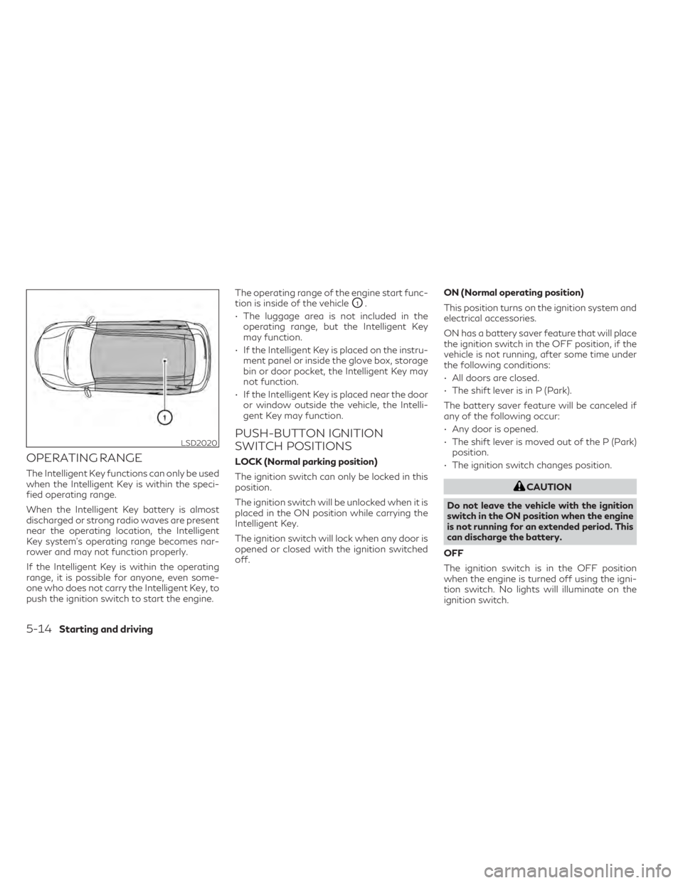
push the ignition switch to start the engine.The operating range of the engine start func-
tion is inside of the vehicle
O1.
• The luggage area is not included in the operating range, but the Intelligent Key
may function.
• If the Intelligent Key is placed on the instru- ment panel or inside the glove box, storage
bin or door pocket, the Intelligent Key may
not function.
• If the Intelligent Key is placed near the door or window outside the vehicle, the Intelli-
gent Key may function.
PUSH-BUTTON IGNITION
SWITCH POSITIONS
LOCK (Normal parking position)
The ignition switch can only be locked in this
position.
The ignition switch will be unlocked when it is
placed in the ON position while carrying the
Intelligent Key.
The ignition switch will lock when any door is
opened or closed with the ignition switched
off. ON (Normal operating position)
This position turns on the ignition system and
electrical accessories.
ON has a battery saver feature that will place
the ignition switch in the OFF position, if the
vehicle is not running, after some time under
the following conditions:
• All doors are closed.
• The shift lever is in P (Park).
The battery saver feature will be canceled if
any of the following occur:
• Any door is opened.
• The shift lever is moved out of the P (Park)
position.
• The ignition switch changes position.
CAUTION
Do not leave the vehicle with the ignition
switch in the ON position when the engine
is not running for an extended period. This
can discharge the battery.
OFF
The ignition switch is in the OFF position
when the engine is turned off using the igni-
tion switch. No lights will illuminate on the
ignition switch.
LSD2020
5-14Starting and driving