torque INFINITI QX50 2022 Owners Manual
[x] Cancel search | Manufacturer: INFINITI, Model Year: 2022, Model line: QX50, Model: INFINITI QX50 2022Pages: 540, PDF Size: 6.58 MB
Page 149 of 540
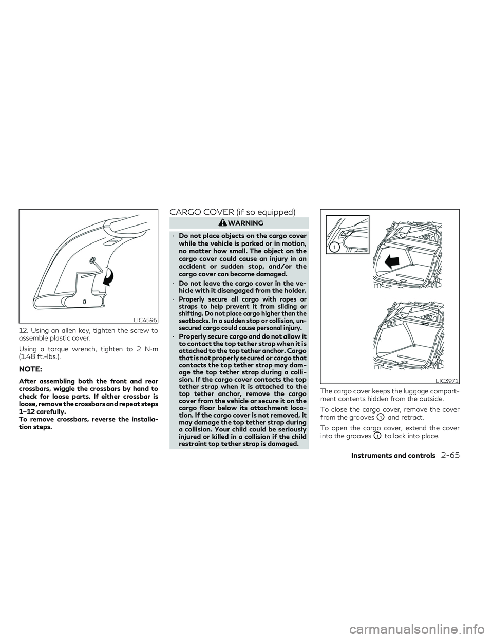
12. Using an allen key, tighten the screw to
assemble plastic cover.
Using a torque wrench, tighten to 2 N•m
(1.48 ft.-lbs.).
NOTE:
After assembling both the front and rear
crossbars, wiggle the crossbars by hand to
check for loose parts. If either crossbar is
loose, remove the crossbars and repeat steps
1–12 carefully.
To remove crossbars, reverse the installa-
tion steps.
CARGO COVER (if so equipped)
WARNING
• Do not place objects on the cargo cover
while the vehicle is parked or in motion,
no matter how small. The object on the
cargo cover could cause an injury in an
accident or sudden stop, and/or the
cargo cover can become damaged.
• Do not leave the cargo cover in the ve-
hicle with it disengaged from the holder.
•
Properly secure all cargo with ropes or
straps to help prevent it from sliding or
shifting. Do not place cargo higher than the
seatbacks. In a sudden stop or collision, un-
secured cargo could cause personal injury.
• Properly secure cargo and do not allow it
to contact the top tether strap when it is
attached to the top tether anchor. Cargo
that is not properly secured or cargo that
contacts the top tether strap may dam-
age the top tether strap during a colli-
sion. If the cargo cover contacts the top
tether strap when it is attached to the
top tether anchor, remove the cargo
cover from the vehicle or secure it on the
cargo floor below its attachment loca-
tion. If the cargo cover is not removed, it
may damage the top tether strap during
a collision. Your child could be seriously
injured or killed in a collision if the child
restraint top tether strap is damaged. The cargo cover keeps the luggage compart-
ment contents hidden from the outside.
To close the cargo cover, remove the cover
from the grooves
O1and retract.
To open the cargo cover, extend the cover
into the grooves
O1to lock into place.
LIC4596
LIC3971
Instruments and controls2-65
Page 273 of 540
• While the electronic parking brake is ap-plied or released, an operating sound is
heard from the lower side of the rear seat.
This is normal and does not indicate a
malfunction.
• When the electronic parking brake is fre- quently applied and released in a short pe-
riod of time, the parking brake may not
operate in order to prevent the parking
brake system from overheating. If this oc-
curs, operate the electronic parking brake
switch again after waiting approximately
1 minute.
• If the electronic parking brake must be ap- plied while driving in an emergency, pull up
and hold the parking brake switch. When
you release the parking brake switch, the
parking brake will be released.
• While pulling up the electronic parking brake switch during driving, the parking
brake is applied and a chime sounds. The
electronic parking brake indicator light
(red) in the meter and in the parking brake
switch illuminates. This does not indicate a
malfunction. The electronic parking brake
indicator light (red) in the meter and in the
parking brake switch turns off when the
parking brake is released. • When pulling the electronic parking brake
switch up with the ignition switch in the
OFF or AUTO ACC position, the parking
brake switch indicator light will continue
to illuminate for a short period of time.
WHEN TOWING A TRAILER
Depending on the weight of the vehicle and
trailer and the steepness of the slope, there
may be a tendency for the vehicle to move
backwards when starting from a standstill.
When this occurs, you can use the parking
brake switch in the same way as a conven-
tional lever type parking brake.
Before starting on sloping roads when tow-
ing a trailer, be sure to read the following to
prevent the vehicle from moving backwards
unintentionally.
• Release the parking brake switch as soonas the engine is delivering enough torque to
the wheels. The automatic brake hold function maintains
the braking force without the driver having to
depress the brake pedal when the vehicle is
stopped at a traffic light or intersection. As
soon as the driver depresses the accelerator
pedal again, the Automatic brake hold func-
tion is deactivated and the braking force is
released.
WARNING
• The Automatic brake hold function is not
designed to hold the vehicle on a steep
hill or slippery road. Never use the Auto-
matic brake hold when the vehicle is
stopped on a steep hill or slippery road.
Failure to do so may cause the vehicle to
move.
• The Automatic brake hold warning may
appear in the vehicle information display
to request that the driver retake control
by depressing the brake pedal.
• When the Automatic brake hold function
is activated but fails to maintain the ve-
hicle at a standstill, depress the brake
pedal to stop the vehicle. If the vehicle
unexpectedly moves due to outside con-
ditions, the chime may sound and Auto-
matic brake hold warning may illuminate
in the vehicle information display.
AUTOMATIC BRAKE HOLD
Starting and driving5-25
Page 345 of 540
NOTE:
If the driver lightly touches (instead of firmly
grips) the steering wheel, the steering
torque sensor may not detect the driver’s
hand(s) on the steering wheel and a sequence
of warnings may occur. When the driver
holds and operates the steering wheel again,
the warnings turn off.
Steering Assist limitations
WARNING
• In the following situations, the camera
may not detect lane markers correctly or
may detect lane markers incorrectly and
the Steering Assist may not operate
properly:
– When driving on roads where there
are multiple parallel lane markers,
lane markers that are faded or not
painted clearly, nonstandard lane
markers, or lane markers covered
with water, dirt, snow, etc.
– When driving on roads with discon-
tinued lane markers
– When driving on roads with a widen-
ing or narrowing lane width –
When driving on roads where there
are multiple lanes or unclear lane
markers due to road construction
– When driving on roads where there
are sharply contrasting objects, such
as shadows, snow, water, wheel ruts,
seams, or lines remaining after road
repairs (the Steering Assist could de-
tect these items as lane markers)
– When driving on roads where the
traveling lane merges or separates
• Do not use the Steering Assist under the
following conditions because the system
may not properly detect lane markers.
Doing so could cause a loss of vehicle
control and result in an accident.
– During bad weather (rain, fog, snow,
dust, etc.)
– When rain, snow, sand, etc., is thrown
up by the wheels of other vehicles
– When dirt, oil, ice, snow, water, or an-
other object adheres to the camera
unit
– When the lens of the camera unit is
foggy
– When strong light (for example, sun-
light or high beams from oncoming
vehicles) shines on the camera –
When the headlights are not bright
due to dirt on the lens or the head-
lights are off in tunnels or darkness
– When a sudden change in brightness
occurs (for example, when the vehicle
enters or exits a tunnel or is under a
bridge)
– When driving on roads where the
traveling lane merges or separates or
where there are temporary lane
markers because of road
construction
– When there is a lane closure due to
road repairs
– When driving on a bumpy road sur-
face, such as an uneven dirt road
– When driving on sharp curves or
winding roads
– When driving on repeated uphill and
downhill roads
• Do not use the Steering Assist under the
following conditions because the system
will not operate properly:
– When driving with a tire that is not
within normal tire conditions (for ex-
ample, tire wear, abnormal tire pres-
sure, installation of a spare tire, tire
chains, nonstandard wheels)
Starting and driving5-97
Page 431 of 540
CAUTION
Be careful not to burn yourself, as the en-
gine oil is hot.
WARNING
• Prolonged and repeated contact with
used engine oil may cause skin cancer.
• Try to avoid direct skin contact with
used oil. If skin contact is made, wash
thoroughly with soap or hand cleaner as
soon as possible.
• Keep used engine oil out of reach of
children.
4. Loosen the oil filter with an oil filter wrench by turning it counterclockwise.
Remove the oil filter by turning it by hand.
5. Wipe the engine oil filter mounting sur- face with a clean rag.
CAUTION
Be sure to remove any old gasket material
remaining on the sealing surface of the en-
gine. Failure to do so could lead to an oil
leak and engine damage. •
The dipstick must be inserted in place to
prevent oil spillage from the dipstick hole
when filling the engine with oil.
6. Coat the gasket on the new filter with clean engine oil.
7. Screw in the oil filter clockwise until a slight resistance is felt, then tighten addi-
tionally more than 2/3 turn.
Oil filter tightening torque: 14.7 to 20.6 N·m (11 to 15 ft-lb)
8. Clean and re-install the drain plug with a new washer. Securely tighten the drain
plug with a wrench. Do not use excessive
force.
Drain plug tightening torque: 29.4 to 39.2 N·m (22 to 29 ft-lb)
9. Refill the engine with the recommended oil through the oil filler opening, and install
the oil filler cap securely.
For additional information about drain and
refill capacity, see “Recommended fluids/
lubricants and capacities” (P. 10-2). The drain
and refill capacity depends on the oil tem-
perature and drain time. Use these specifica-
tions for reference only. Always use the dip-
stick to determine the proper amount of oil in
the engine. 10. Start the engine and check for leakage
around the drain plug and the oil filter.
Correct as required. Turn the engine off
and wait more than 15 minutes. Check
the oil level with the dipstick. Add engine
oil if necessary.
After the operation
1. Reinstall engine protectors in reverse or-der of removal.
2. Lower the vehicle carefully to the ground.
3. Reset the oil control system. For addi- tional information, see “Oil control sys-
tem” (P. 2-20)
• Dispose of waste oil and filter properly.
• Check your local regulations.
Do-it-yourself8-9
Page 460 of 540
TIRE CHAINS
CAUTION
Tire chains/cables should not be installed
on P255/45RF20 size tires. Installation of
the tire chains/cables on P255/45RF20
size tires will cause damage to the vehicle.
If you plan to use tire chains/cables, you
should install P235/55RF19 size tires on
your vehicle.
Use of tire chains may be prohibited accord-
ing to location. Check the local laws before
installing tire chains. When installing tire
chains, make sure they are the proper size for
the tires on your vehicle and are installed
according to the chain manufacturer's sug-
gestions. Use only SAE class “S” chains. Class
“S” chains are used on vehicles with restricted
tire to vehicle clearance. Vehicles that can use
Class “S” chains are designed to meet the
minimum clearances between the tire and the
closest vehicle suspension or body compo-
nent required to accommodate the use of a
winter traction device (tire chains or cables).
The minimum clearances are determined us-
ing the factory equipped tire size. Other types
may damage your vehicle. Use chain tension-
ers when recommended by the tire chain
manufacturer to ensure a tight fit. Loose end
links of the tire chain must be secured or removed to prevent the possibility of whip-
ping action damage to the fenders or under-
body. If possible, avoid fully loading your ve-
hicle when using tire chains. In addition, drive
at a reduced speed. Otherwise, your vehicle
may be damaged and/or vehicle handling
and performance may be adversely affected.
Do not use tire chains on dry roads. Driving
with chains in such conditions can cause
damage to the various mechanisms of the
vehicle due to some overstress.
CHANGING WHEELS AND TIRES
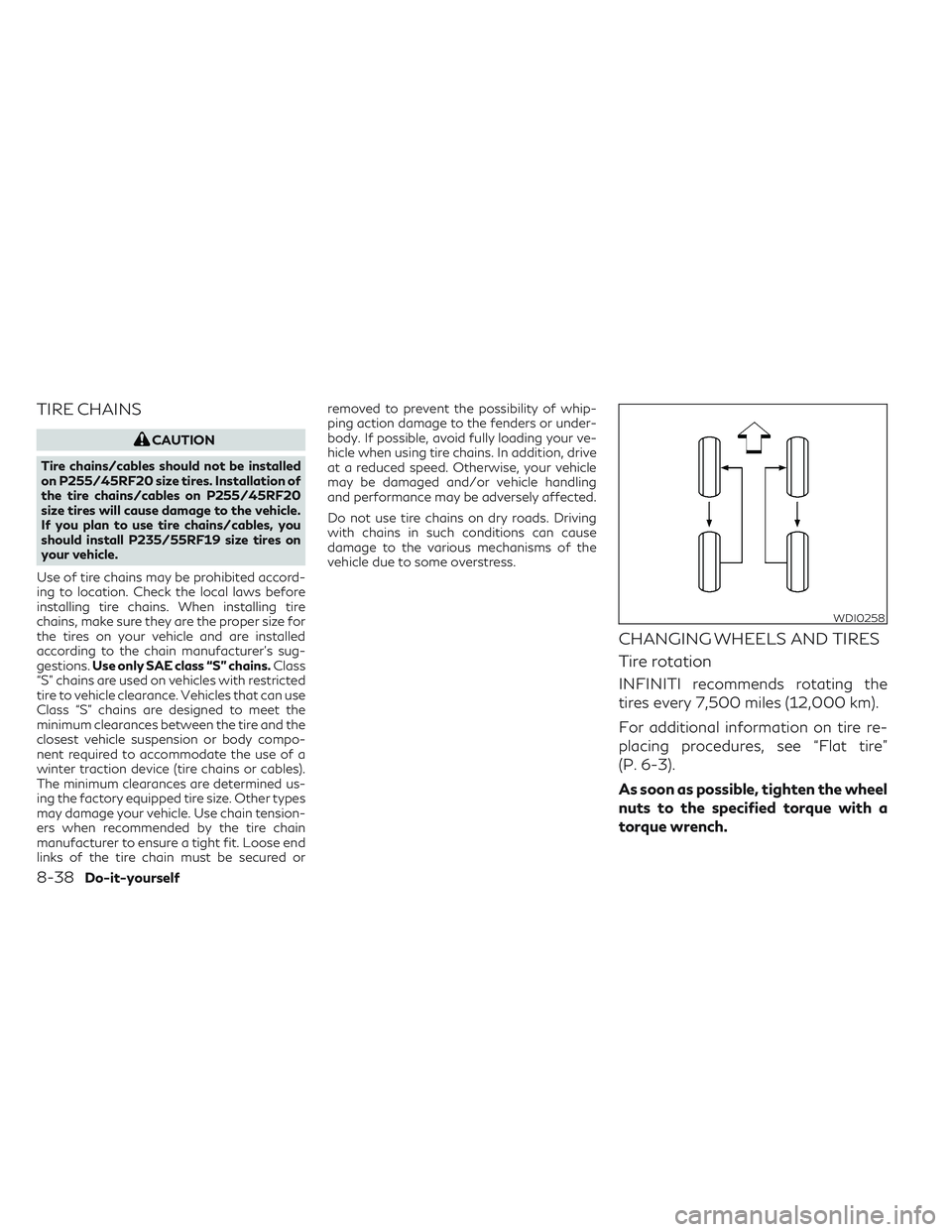
Tire rotation
INFINITI recommends rotating the
tires every 7,500 miles (12,000 km).
For additional information on tire re-
placing procedures, see “Flat tire”
(P. 6-3).
As soon as possible, tighten the wheel
nuts to the specified torque with a
torque wrench.
WDI0258
8-38Do-it-yourself
Page 461 of 540
Wheel nut tightening torque:83 ft-lb (113 N·m)
The wheel nuts must be kept tight-
ened to specifications at all times. It is
recommended that wheel nuts be
tightened to specification at each tire
rotation interval.
WARNING
•
After rotating the tires, check and
adjust the tire pressure.
•Do not include the spare tire in the
tire rotation.
•For additional information re-
garding tires, refer to “Important
Tire Safety Information” (US) or
“Tire Safety Information”
(Canada) in the Warranty Infor-
mation Booklet.
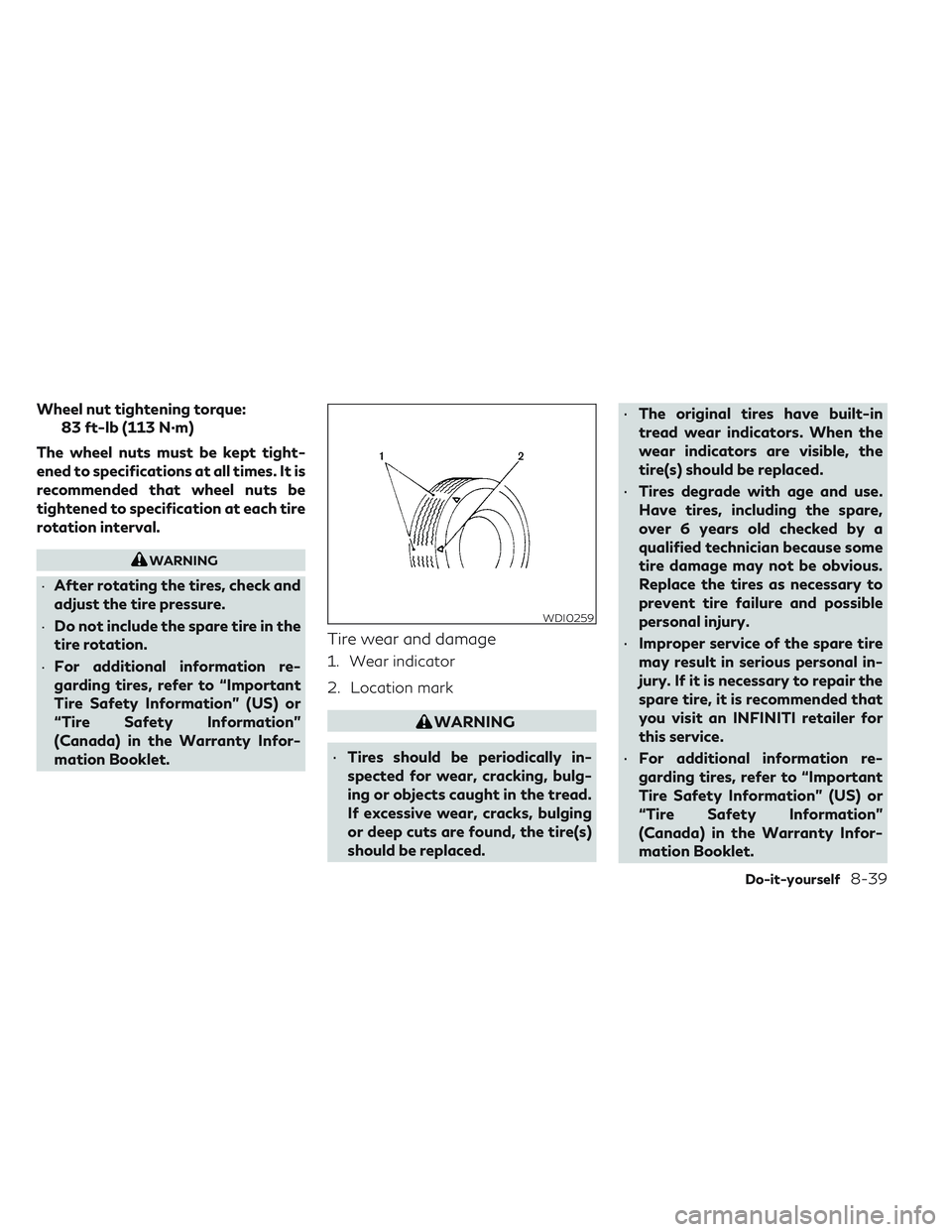
Tire wear and damage
1. Wear indicator
2. Location mark
WARNING
• Tires should be periodically in-
spected for wear, cracking, bulg-
ing or objects caught in the tread.
If excessive wear, cracks, bulging
or deep cuts are found, the tire(s)
should be replaced. •
The original tires have built-in
tread wear indicators. When the
wear indicators are visible, the
tire(s) should be replaced.
• Tires degrade with age and use.
Have tires, including the spare,
over 6 years old checked by a
qualified technician because some
tire damage may not be obvious.
Replace the tires as necessary to
prevent tire failure and possible
personal injury.
• Improper service of the spare tire
may result in serious personal in-
jury. If it is necessary to repair the
spare tire, it is recommended that
you visit an INFINITI retailer for
this service.
• For additional information re-
garding tires, refer to “Important
Tire Safety Information” (US) or
“Tire Safety Information”
(Canada) in the Warranty Infor-
mation Booklet.
WDI0259
Do-it-yourself8-39