INFINITI QX50 2023 Owners Manual
Manufacturer: INFINITI, Model Year: 2023, Model line: QX50, Model: INFINITI QX50 2023Pages: 548, PDF Size: 6.17 MB
Page 221 of 548
AROUND VIEW® MONITOR
SYSTEM OPERATION
With the engine running, move the shift lever
to the R (Reverse) position or press the
CAMERA button to operate the Around
View® Monitor. When activating the Around
View® Monitor, the guide lines, the icons
and the messages may not be displayed
immediately.
When the camera is first activated with the
bird’s-eye view in the display, a red icon will
flash on the upper display. This indicates that
the sonar system is activated. For additional
information on the front and rear sonar sys-
tem, see “Front and rear sonar system”
(P. 5-147).
Available views
WARNING
• The distance guide lines and the vehicle
width lines should be used as a reference
only when the vehicle is on a paved, level
surface. The apparent distance viewed
on the monitor may be different than the
actual distance between the vehicle and
displayed objects.
• Use the displayed lines and the bird’s-
eye view as a reference. The lines and the
bird’s-eye view are greatly affected by
the number of occupants, cargo, fuel
level, vehicle position, road condition
and road grade.
• If the tires are replaced with different
sized tires, the predicted course lines and
the bird's-eye view may be displayed
incorrectly.
• When driving the vehicle up a hill, objects
viewed in the monitor are further than
they appear. When driving the vehicle
down a hill, objects viewed in the monitor
are closer than they appear. •
Objects in the rear view will appear visu-
ally opposite compared to when viewed
in the monitor and outside mirrors.
• Use the mirrors or actually look to prop-
erly judge distances to other objects.
• On a snow-covered or slippery road,
there may be a difference between the
predicted course lines and the actual
course line.
• The vehicle width and predicted course
lines are wider than the actual width and
course.
• The displayed lines will appear slightly
off to the right, because the rearview
camera is not installed in the rear center
of the vehicle.
Monitor, climate, audio, phone and voice recognition systems4-13
Page 222 of 548
Front and rear view
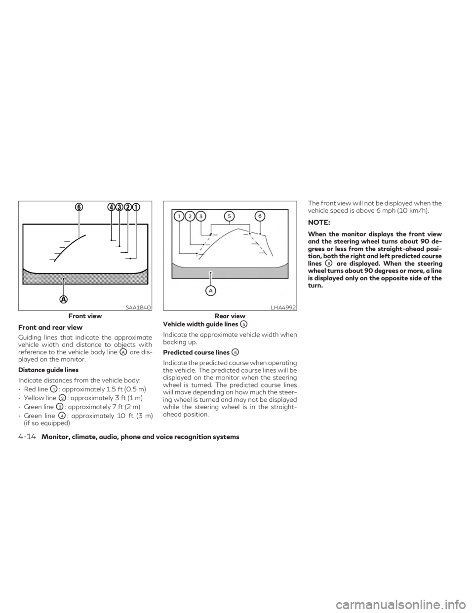
Guiding lines that indicate the approximate
vehicle width and distance to objects with
reference to the vehicle body line
OAare dis-
played on the monitor.
Distance guide lines
Indicate distances from the vehicle body:
• Red line
O1: approximately 1.5 ft (0.5 m)
• Yellow line
O2: approximately 3 ft (1 m)
• Green line
O3: approximately 7 ft (2 m)
• Green line
O4: approximately 10 ft (3 m)
(if so equipped) Vehicle width guide lines
O5
Indicate the approximate vehicle width when
backing up.
Predicted course lines
O6
Indicate the predicted course when operating
the vehicle. The predicted course lines will be
displayed on the monitor when the steering
wheel is turned. The predicted course lines
will move depending on how much the steer-
ing wheel is turned and may not be displayed
while the steering wheel is in the straight-
ahead position. The front view will not be displayed when the
vehicle speed is above 6 mph (10 km/h).
NOTE:
When the monitor displays the front view
and the steering wheel turns about 90 de-
grees or less from the straight-ahead posi-
tion, both the right and left predicted course
lines
O6are displayed. When the steering
wheel turns about 90 degrees or more, a line
is displayed only on the opposite side of the
turn.
SAA1840
Front view
LHA4992
Rear view
4-14Monitor, climate, audio, phone and voice recognition systems
Page 223 of 548
Bird’s-eye view
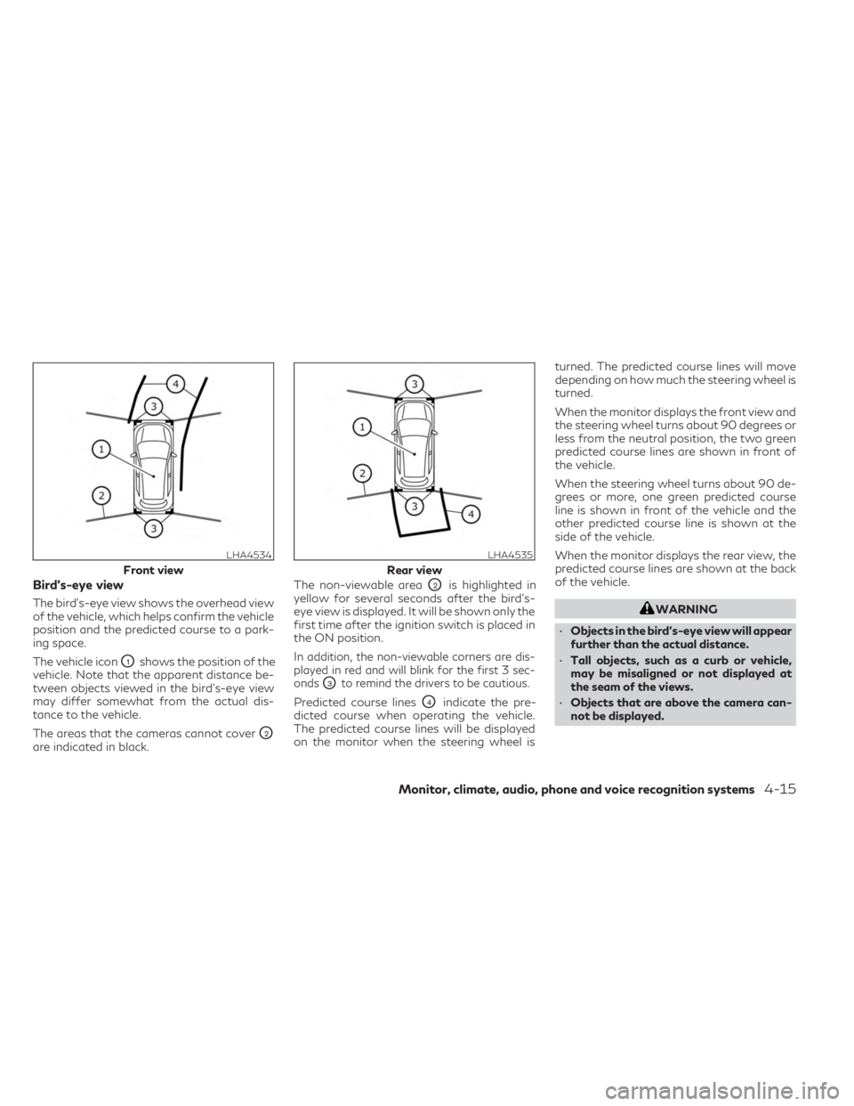
The bird's-eye view shows the overhead view
of the vehicle, which helps confirm the vehicle
position and the predicted course to a park-
ing space.
The vehicle icon
O1shows the position of the
vehicle. Note that the apparent distance be-
tween objects viewed in the bird's-eye view
may differ somewhat from the actual dis-
tance to the vehicle.
The areas that the cameras cannot cover
O2
are indicated in black. The non-viewable area
O2is highlighted in
yellow for several seconds after the bird’s-
eye view is displayed. It will be shown only the
first time after the ignition switch is placed in
the ON position.
In addition, the non-viewable corners are dis-
played in red and will blink for the first 3 sec-
onds
O3to remind the drivers to be cautious.
Predicted course linesO4indicate the pre-
dicted course when operating the vehicle.
The predicted course lines will be displayed
on the monitor when the steering wheel is turned. The predicted course lines will move
depending on how much the steering wheel is
turned.
When the monitor displays the front view and
the steering wheel turns about 90 degrees or
less from the neutral position, the two green
predicted course lines are shown in front of
the vehicle.
When the steering wheel turns about 90 de-
grees or more, one green predicted course
line is shown in front of the vehicle and the
other predicted course line is shown at the
side of the vehicle.
When the monitor displays the rear view, the
predicted course lines are shown at the back
of the vehicle.
WARNING
• Objects in the bird's-eye view will appear
further than the actual distance.
• Tall objects, such as a curb or vehicle,
may be misaligned or not displayed at
the seam of the views.
• Objects that are above the camera can-
not be displayed.
LHA4534
Front view
LHA4535
Rear view
Monitor, climate, audio, phone and voice recognition systems4-15
Page 224 of 548
•The view of the bird's-eye view may be
misaligned when the camera position
alters.
• A line on the ground may be misaligned
and is not seen as being straight at the
seam of the views. The misalignment will
increase as the line proceeds away from
the vehicle.
Front-side view
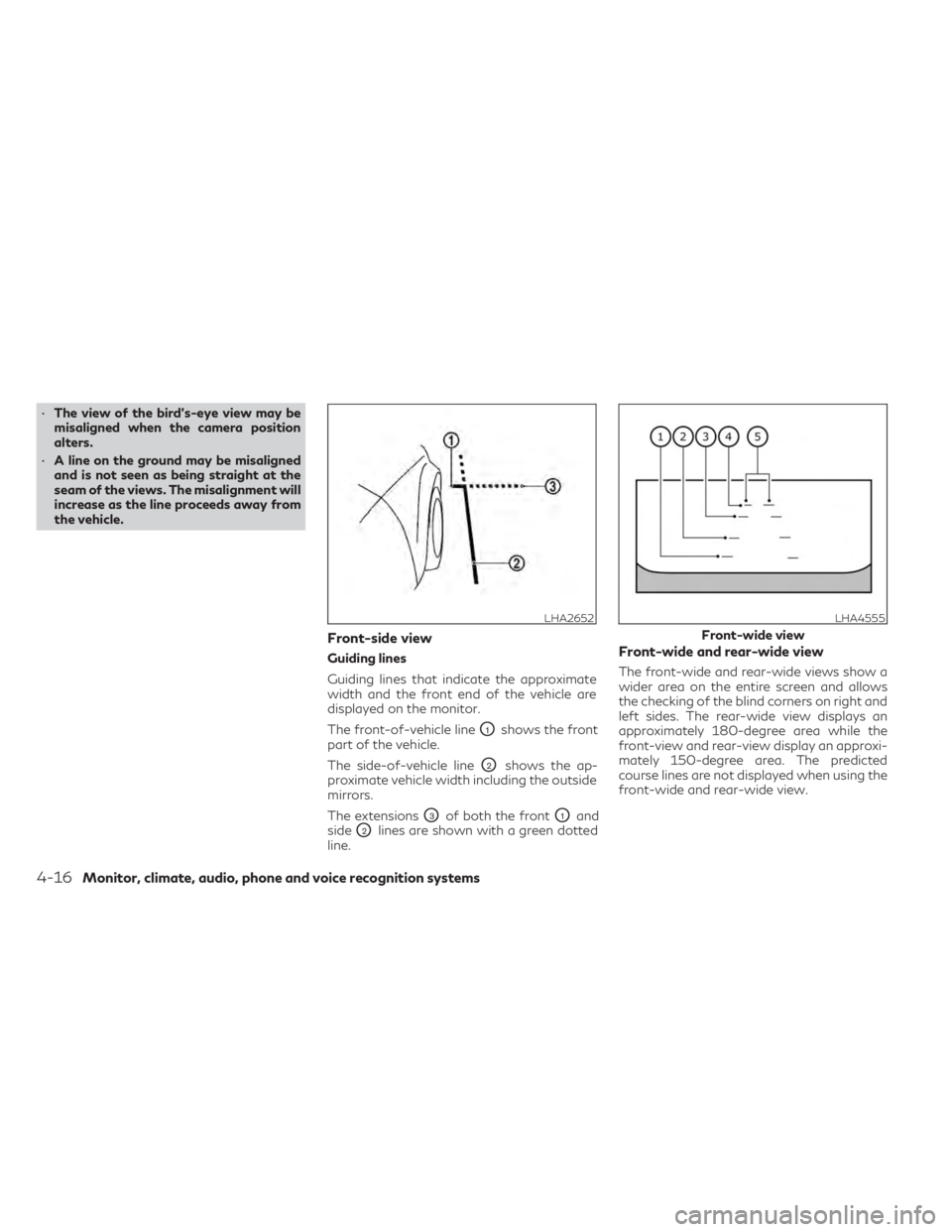
Guiding lines
Guiding lines that indicate the approximate
width and the front end of the vehicle are
displayed on the monitor.
The front-of-vehicle line
O1shows the front
part of the vehicle.
The side-of-vehicle line
O2shows the ap-
proximate vehicle width including the outside
mirrors.
The extensions
O3of both the frontO1and
side
O2lines are shown with a green dotted
line.
Front-wide and rear-wide view
The front-wide and rear-wide views show a
wider area on the entire screen and allows
the checking of the blind corners on right and
left sides. The rear-wide view displays an
approximately 180-degree area while the
front-view and rear-view display an approxi-
mately 150-degree area. The predicted
course lines are not displayed when using the
front-wide and rear-wide view.
LHA2652LHA4555
Front-wide view
4-16Monitor, climate, audio, phone and voice recognition systems
Page 225 of 548
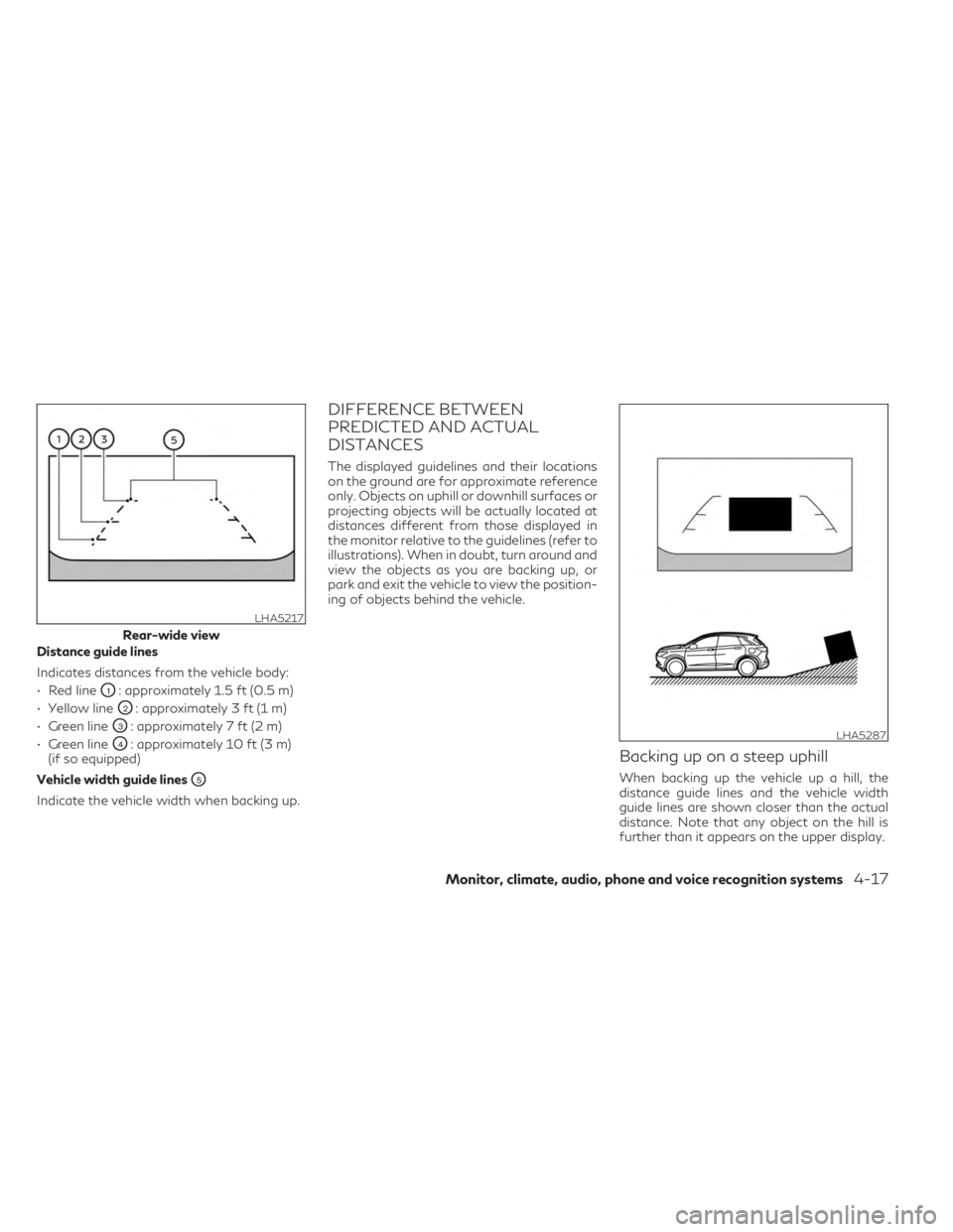
Distance guide lines
Indicates distances from the vehicle body:
• Red line
O1: approximately 1.5 ft (0.5 m)
• Yellow line
O2: approximately 3 ft (1 m)
• Green line
O3: approximately 7 ft (2 m)
• Green line
O4: approximately 10 ft (3 m)
(if so equipped)
Vehicle width guide lines
O5
Indicate the vehicle width when backing up.
DIFFERENCE BETWEEN
PREDICTED AND ACTUAL
DISTANCES
The displayed guidelines and their locations
on the ground are for approximate reference
only. Objects on uphill or downhill surfaces or
projecting objects will be actually located at
distances different from those displayed in
the monitor relative to the guidelines (refer to
illustrations). When in doubt, turn around and
view the objects as you are backing up, or
park and exit the vehicle to view the position-
ing of objects behind the vehicle.
Backing up on a steep uphill
When backing up the vehicle up a hill, the
distance guide lines and the vehicle width
guide lines are shown closer than the actual
distance. Note that any object on the hill is
further than it appears on the upper display.
LHA5217
Rear-wide view
LHA5287
Monitor, climate, audio, phone and voice recognition systems4-17
Page 226 of 548
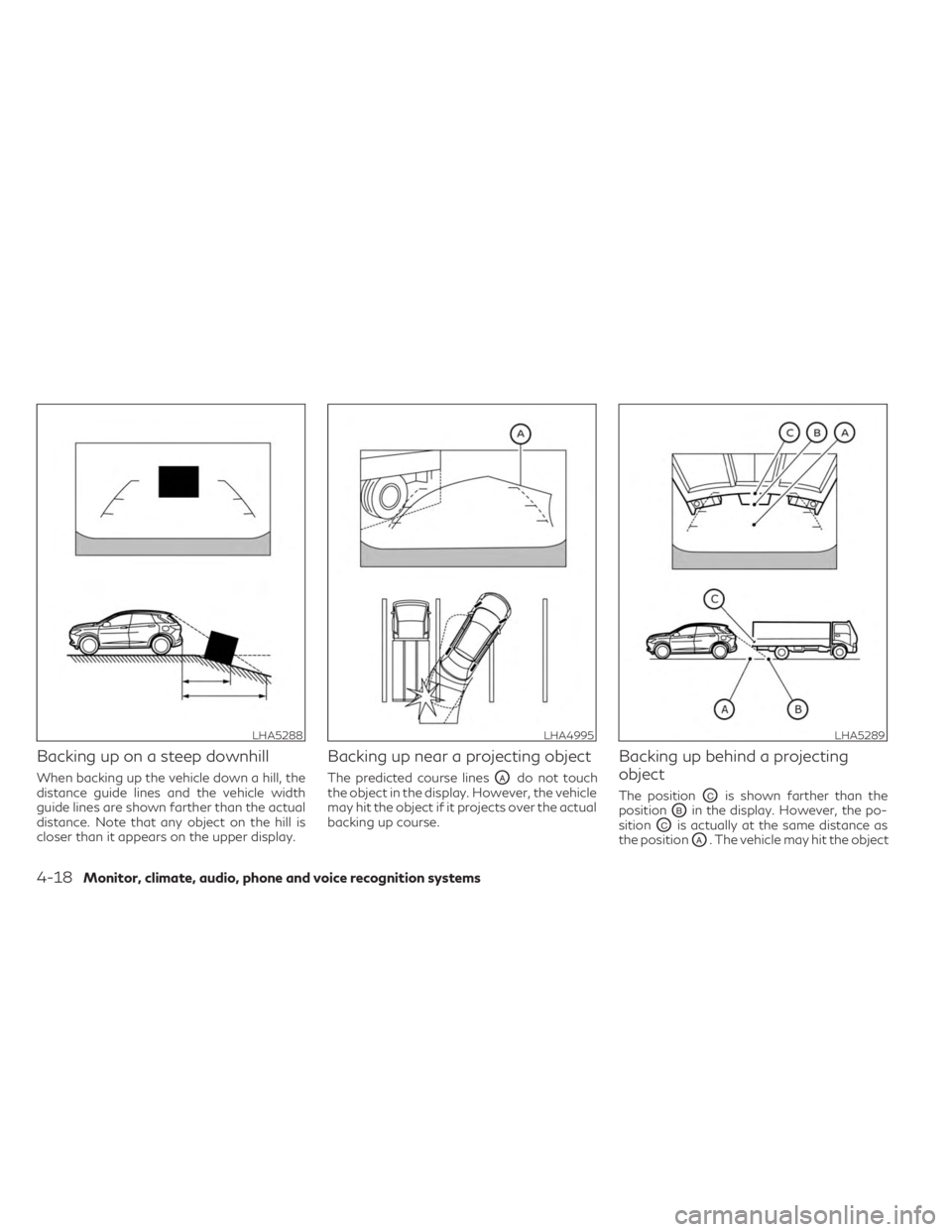
Backing up on a steep downhill
When backing up the vehicle down a hill, the
distance guide lines and the vehicle width
guide lines are shown farther than the actual
distance. Note that any object on the hill is
closer than it appears on the upper display.
Backing up near a projecting object
The predicted course linesOAdo not touch
the object in the display. However, the vehicle
may hit the object if it projects over the actual
backing up course.
Backing up behind a projecting
object
The positionOCis shown farther than the
position
OBin the display. However, the po-
sition
OCis actually at the same distance as
the position
OA. The vehicle may hit the object
LHA5288LHA4995LHA5289
4-18Monitor, climate, audio, phone and voice recognition systems
Page 227 of 548
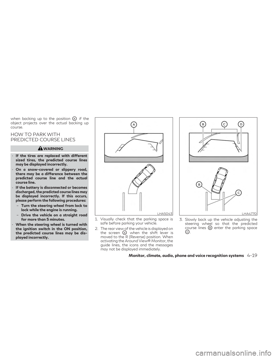
when backing up to the positionOAif the
object projects over the actual backing up
course.
HOW TO PARK WITH
PREDICTED COURSE LINES
WARNING
• If the tires are replaced with different
sized tires, the predicted course lines
may be displayed incorrectly.
• On a snow-covered or slippery road,
there may be a difference between the
predicted course line and the actual
course line.
•
If the battery is disconnected or becomes
discharged, the predicted course lines may
be displayed incorrectly. If this occurs,
please perform the following procedures:
– Turn the steering wheel from lock to
lock while the engine is running.
– Drive the vehicle on a straight road
for more than 5 minutes.
• When the steering wheel is turned with
the ignition switch in the ON position,
the predicted course lines may be dis-
played incorrectly. 1. Visually check that the parking space is
safe before parking your vehicle.
2. The rear view of the vehicle is displayed on the screen
OAwhen the shift lever is
moved to the R (Reverse) position. When
activating the Around View® Monitor, the
guide lines, the icons and the messages
may not be displayed immediately. 3. Slowly back up the vehicle adjusting the
steering wheel so that the predicted
course linesOBenter the parking space
OC.
LHA5043LHA4770
Monitor, climate, audio, phone and voice recognition systems4-19
Page 228 of 548
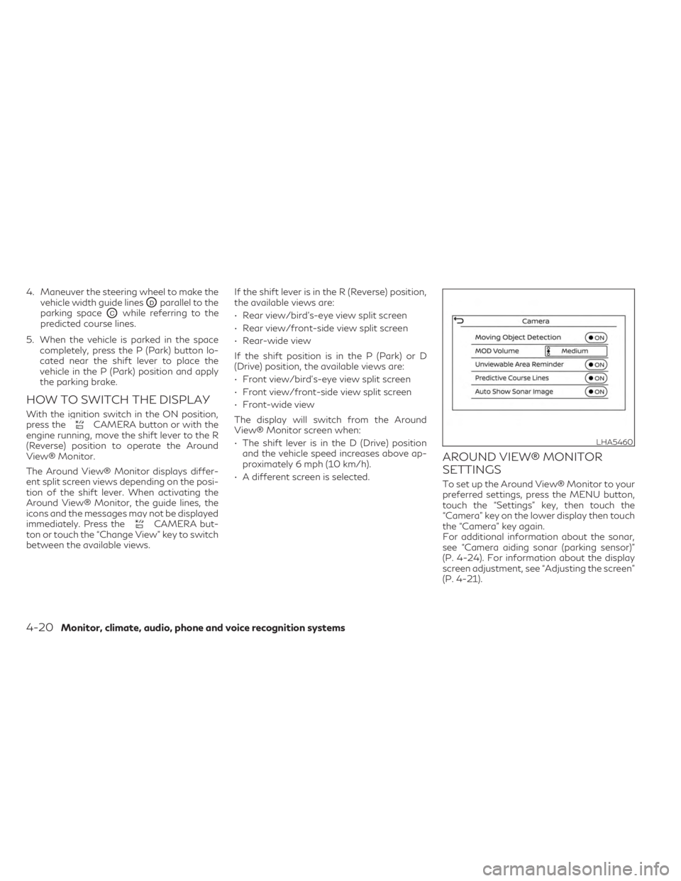
4. Maneuver the steering wheel to make thevehicle width guide lines
ODparallel to the
parking space
OCwhile referring to the
predicted course lines.
5. When the vehicle is parked in the space completely, press the P (Park) button lo-
cated near the shift lever to place the
vehicle in the P (Park) position and apply
the parking brake.
HOW TO SWITCH THE DISPLAY
With the ignition switch in the ON position,
press theCAMERA button or with the
engine running, move the shift lever to the R
(Reverse) position to operate the Around
View® Monitor.
The Around View® Monitor displays differ-
ent split screen views depending on the posi-
tion of the shift lever. When activating the
Around View® Monitor, the guide lines, the
icons and the messages may not be displayed
immediately. Press the
CAMERA but-
ton or touch the “Change View” key to switch
between the available views. If the shift lever is in the R (Reverse) position,
the available views are:
• Rear view/bird’s-eye view split screen
• Rear view/front-side view split screen
• Rear-wide view
If the shift position is in the P (Park) or D
(Drive) position, the available views are:
• Front view/bird’s-eye view split screen
• Front view/front-side view split screen
• Front-wide view
The display will switch from the Around
View® Monitor screen when:
• The shift lever is in the D (Drive) position
and the vehicle speed increases above ap-
proximately 6 mph (10 km/h).
• A different screen is selected.
AROUND VIEW® MONITOR
SETTINGS
To set up the Around View® Monitor to your
preferred settings, press the MENU button,
touch the “Settings” key, then touch the
“Camera” key on the lower display then touch
the “Camera” key again.
For additional information about the sonar,
see “Camera aiding sonar (parking sensor)”
(P. 4-24). For information about the display
screen adjustment, see “Adjusting the screen”
(P. 4-21).
LHA5460
4-20Monitor, climate, audio, phone and voice recognition systems
Page 229 of 548
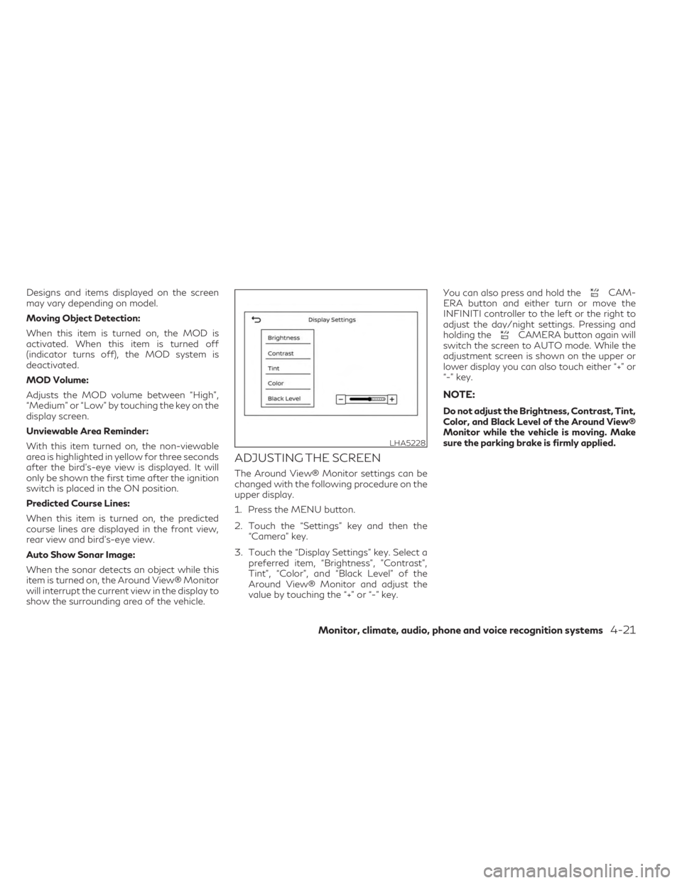
Designs and items displayed on the screen
may vary depending on model.
Moving Object Detection:
When this item is turned on, the MOD is
activated. When this item is turned off
(indicator turns off), the MOD system is
deactivated.
MOD Volume:
Adjusts the MOD volume between “High”,
“Medium” or “Low” by touching the key on the
display screen.
Unviewable Area Reminder:
With this item turned on, the non-viewable
area is highlighted in yellow for three seconds
after the bird's-eye view is displayed. It will
only be shown the first time after the ignition
switch is placed in the ON position.
Predicted Course Lines:
When this item is turned on, the predicted
course lines are displayed in the front view,
rear view and bird's-eye view.
Auto Show Sonar Image:
When the sonar detects an object while this
item is turned on, the Around View® Monitor
will interrupt the current view in the display to
show the surrounding area of the vehicle.
ADJUSTING THE SCREEN
The Around View® Monitor settings can be
changed with the following procedure on the
upper display.
1. Press the MENU button.
2. Touch the “Settings” key and then the“Camera” key.
3. Touch the “Display Settings” key. Select a preferred item, “Brightness”, ”Contrast”,
Tint”, “Color”, and “Black Level” of the
Around View® Monitor and adjust the
value by touching the “+” or “-” key. You can also press and hold the
CAM-
ERA button and either turn or move the
INFINITI controller to the left or the right to
adjust the day/night settings. Pressing and
holding the
CAMERA button again will
switch the screen to AUTO mode. While the
adjustment screen is shown on the upper or
lower display you can also touch either “+” or
“-” key.
NOTE:
Do not adjust the Brightness, Contrast, Tint,
Color, and Black Level of the Around View®
Monitor while the vehicle is moving. Make
sure the parking brake is firmly applied.
LHA5228
Monitor, climate, audio, phone and voice recognition systems4-21
Page 230 of 548
AROUND VIEW® MONITOR
SYSTEM LIMITATIONS
WARNING
Listed below are the system limitations for
Around View® Monitor. Failure to operate
the vehicle in accordance with these sys-
tem limitations could result in serious in-
jury or death.
• Do not use the Around View® Monitor
with the outside mirrors in the stored po-
sition, and make sure that the liftgate is
securely closed when operating the ve-
hicle using the Around View® Monitor.
• The apparent distance between objects
viewed on the Around View® Monitor
differs from the actual distance.
• The cameras are installed on the front
grille, the outside mirrors and above the
rear license plate. Do not put anything on
the vehicle that covers the cameras.
• When washing the vehicle with high
pressure water, be sure not to spray it
around the cameras. Otherwise, water
may enter the camera unit causing water
condensation on the lens, a malfunction,
fire or an electric shock.
• Do not strike the cameras. They are pre-
cision instruments. Doing so could cause
a malfunction or cause damage resulting
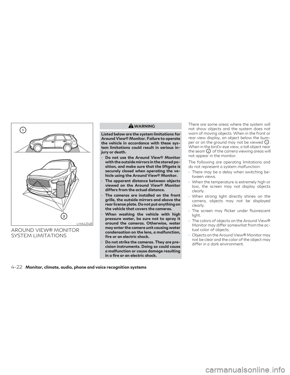
in a fire or an electric shock. There are some areas where the system will
not show objects and the system does not
warn of moving objects. When in the front or
rear view display, an object below the bum-
per or on the ground may not be viewed
O1.
When in the bird’s-eye view, a tall object near
the seam
O2of the camera viewing areas will
not appear in the monitor.
The following are operating limitations and
do not represent a system malfunction:
• There may be a delay when switching be- tween views.
• When the temperature is extremely high or low, the screen may not display objects
clearly.
• When strong light directly shines on the camera, objects may not be displayed
clearly.
• The screen may flicker under fluorescent light.
• The colors of objects on the Around View® Monitor may differ somewhat from the ac-
tual color of objects.
• Objects on the Around View® Monitor may not be clear and the color of the object may
differ in a dark environment.
LHA4348
4-22Monitor, climate, audio, phone and voice recognition systems