ECU INFINITI QX56 2008 Factory Service Manual
[x] Cancel search | Manufacturer: INFINITI, Model Year: 2008, Model line: QX56, Model: INFINITI QX56 2008Pages: 4083, PDF Size: 81.73 MB
Page 454 of 4083

BR-34
< ON-VEHICLE REPAIR >
REAR DISC BRAKE
REAR DISC BRAKE
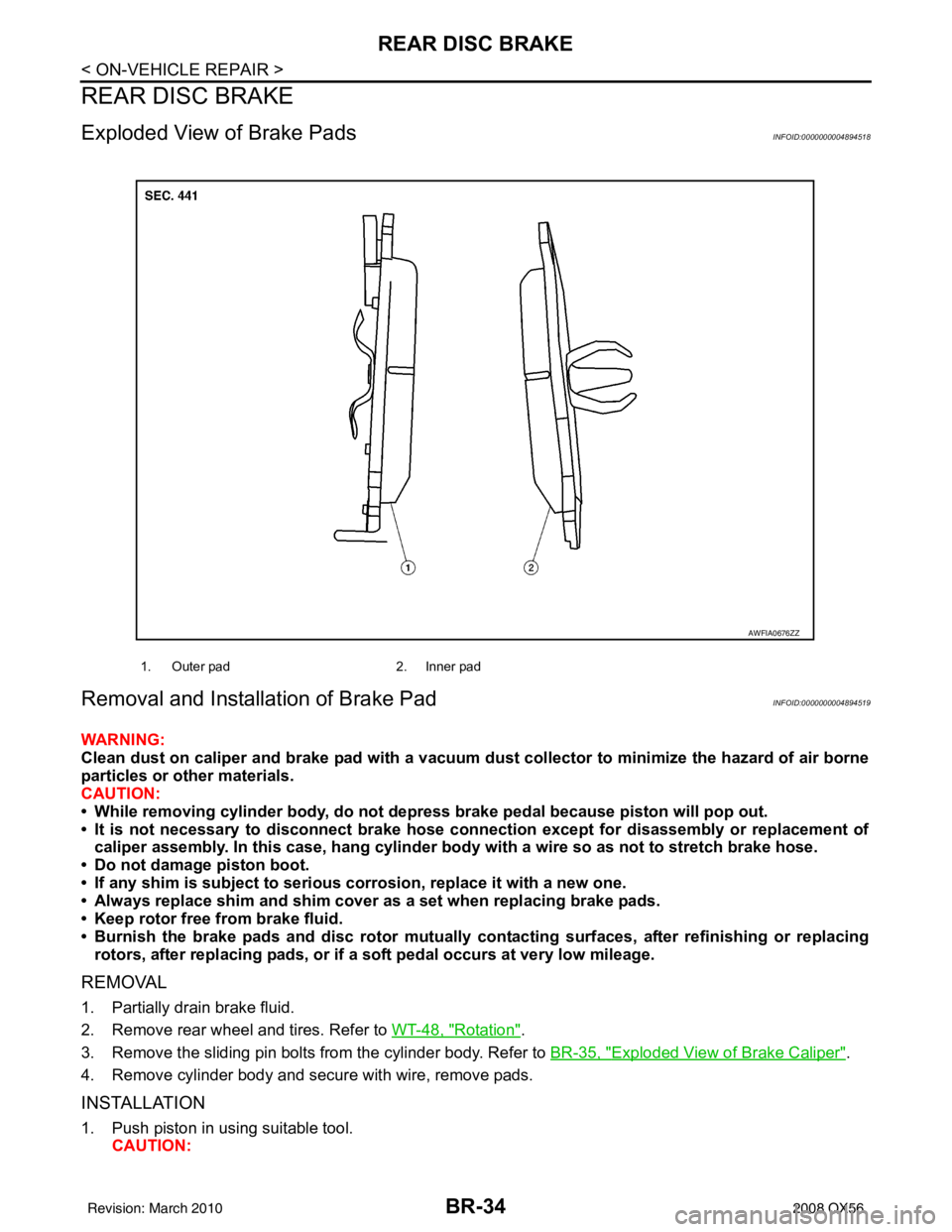
Exploded View of Brake PadsINFOID:0000000004894518
Removal and Installation of Brake PadINFOID:0000000004894519
WARNING:
Clean dust on caliper and brake pad with a vacuum dust collector to minimize the hazard of air borne
particles or other materials.
CAUTION:
• While removing cylinder body, do not depress brake pedal because piston will pop out.
• It is not necessary to disconnect brake hose connection except for disassembly or replacement of caliper assembly. In this case, ha ng cylinder body with a wire so as not to stretch brake hose.
• Do not damage piston boot.
• If any shim is subject to serious corrosion, replace it with a new one.
• Always replace shim and shim cover as a set when replacing brake pads.
• Keep rotor free from brake fluid.
• Burnish the brake pads and disc rotor mutually contacting surfaces, after refinishing or replacing
rotors, after replacing pads, or if a soft pedal occurs at very low mileage.
REMOVAL
1. Partially drain brake fluid.
2. Remove rear wheel and tires. Refer to WT-48, "
Rotation".
3. Remove the sliding pin bolts from the cylinder body. Refer to BR-35, "
Exploded View of Brake Caliper".
4. Remove cylinder body and secure with wire, remove pads.
INSTALLATION
1. Push piston in using suitable tool. CAUTION:
1. Outer pad 2. Inner pad
AWFIA0676ZZ
Revision: March 2010 2008 QX56
Page 455 of 4083

REAR DISC BRAKEBR-35
< ON-VEHICLE REPAIR >
C
DE
G H
I
J
K L
M A
B
BR
N
O P
By pushing in piston, br ake fluid returns to master cylinder reservoir tank. Watch the brake fluid
level in the reservoir tank.
NOTE:
Using a suitable tool, makes it easier to push in the piston.
2. Apply Molykote AS-880N grease to knuckle slide where brake pads contact. CAUTION:
Do not get grease on the brake pads or brake rotor friction surfaces.
3. Install pads to cylinder body.
4. Install cylinder body to torque member.
5. Install cylinder body sliding pin bolts and tighten to specification. Refer to BR-35, "
Exploded View of Brake
Caliper".
6. Check rear disc brake for drag.
7. Install rear wheel and tires. Refer to WT-48, "
Rotation".
8. Check brake fluid level. Refer to BR-17, "
On Board Inspection"
Brake Burnishing ProcedureINFOID:0000000004894520
Burnish contact surfaces between disc rotors and pads according to following procedure after refinishing or
replacing rotors, after replacing pads, or if a soft pedal occurs at very low mileage.
CAUTION:
• Be careful of vehicle speed because the brake does not operate easily until pad and disc rotor are securely seated.
• Only perform this procedure under safe road and traffic conditions. Use extreme caution.
1. Drive vehicle on straight, flat road.
2. Depress brake pedal with the power to stop vehicle within 3 to 5 seconds until the vehicle stops.
3. Drive without depressing brake for a few minutes to cool the brake.
4. Repeat steps 1 through 3 until pad and disc rotor are securely seated.
Exploded View of Brake CaliperINFOID:0000000004894521
AWFIA0684GB
Revision: March 2010 2008 QX56
Page 456 of 4083

BR-36
< ON-VEHICLE REPAIR >
REAR DISC BRAKE
Removal and Installation of Brake Caliper and Disc Rotor
INFOID:0000000004894522
WARNING:
Clean dust on caliper and brake pad with a vacuum dust collector to minimize the hazard of air borne
particles or other materials.
CAUTION:
• While removing cylinder body, do not depress brake pedal because piston will pop out.
• Do not damage piston boot.
• Keep rotor free from brake fluid.
• Refill with new specified brake fluid.
• Burnish brake contact surface after refinishing or re placing rotors, after replacing pads, or it a soft
pedal occurs at very low mileage. Refer to BR-35, "
Brake Burnishing Procedure".
REMOVAL
1. Remove rear wheel and tires. Refer to WT-48, "Rotation".
2. Fasten disc rotor using wheel nut.
3. Drain brake fluid as necessary. Refer to BR-17, "
Drain and Refill".
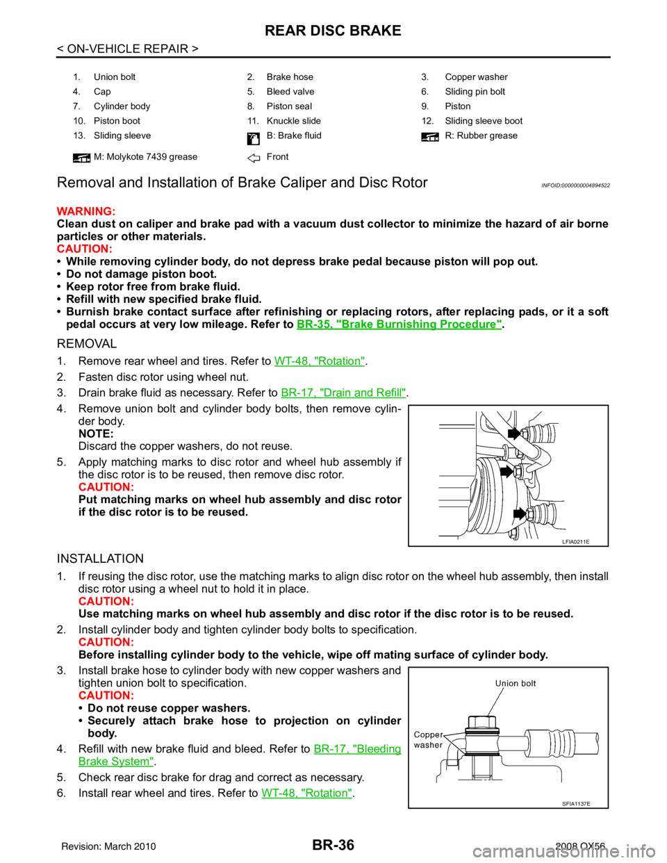
4. Remove union bolt and cylinder body bolts, then remove cylin- der body.
NOTE:
Discard the copper washers, do not reuse.
5. Apply matching marks to disc rotor and wheel hub assembly if the disc rotor is to be reused, then remove disc rotor.
CAUTION:
Put matching marks on wheel hub assembly and disc rotor
if the disc rotor is to be reused.
INSTALLATION
1. If reusing the disc rotor, use the matching marks to align disc rotor on the wheel hub assembly, then install
disc rotor using a wheel nut to hold it in place.
CAUTION:
Use matching marks on wheel hub assembly and di sc rotor if the disc rotor is to be reused.
2. Install cylinder body and tighten cylinder body bolts to specification. CAUTION:
Before installing cylinder body to the vehic le, wipe off mating surface of cylinder body.
3. Install brake hose to cylinder body with new copper washers and tighten union bolt to specification.
CAUTION:
• Do not reuse copper washers.
• Securely attach brake hose to projection on cylinderbody.
4. Refill with new brake fluid and bleed. Refer to BR-17, "
Bleeding
Brake System".
5. Check rear disc brake for drag and correct as necessary.
6. Install rear wheel and tires. Refer to WT-48, "
Rotation".
1. Union bolt 2. Brake hose 3. Copper washer
4. Cap 5. Bleed valve 6. Sliding pin bolt
7. Cylinder body 8. Piston seal9. Piston
10. Piston boot 11. Knuckle slide 12. Sliding sleeve boot
13. Sliding sleeve B: Brake fluidR: Rubber grease
M: Molykote 7439 grease Front
LFIA0211E
SFIA1137E
Revision: March 2010 2008 QX56
Page 461 of 4083

FRONT DISC BRAKEBR-41
< DISASSEMBLY AND ASSEMBLY >
C
DE
G H
I
J
K L
M A
B
BR
N
O P
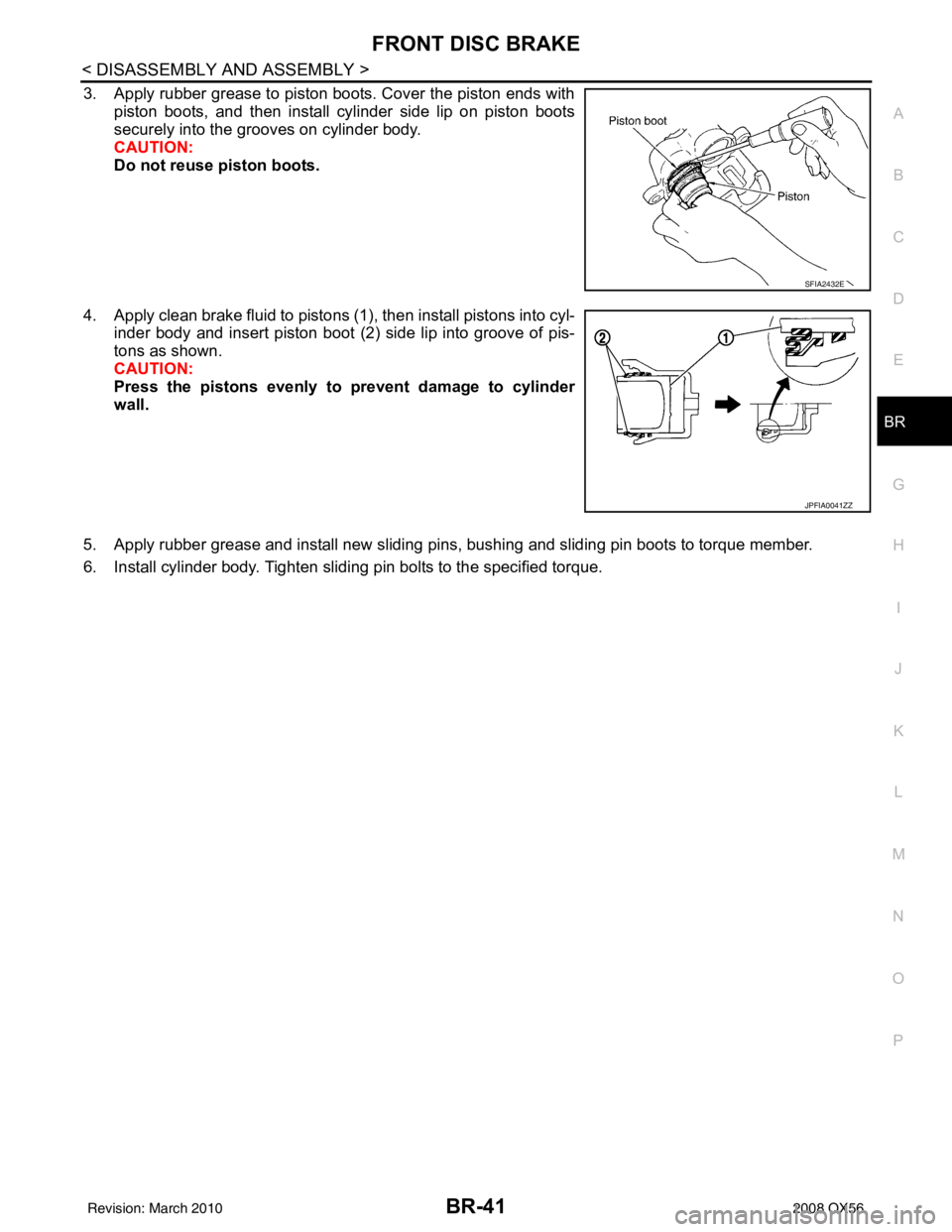
3. Apply rubber grease to piston boots. Cover the piston ends with piston boots, and then install cylinder side lip on piston boots
securely into the grooves on cylinder body.
CAUTION:
Do not reuse piston boots.
4. Apply clean brake fluid to pistons (1), then install pistons into cyl- inder body and insert piston boot (2) side lip into groove of pis-
tons as shown.
CAUTION:
Press the pistons evenly to prevent damage to cylinder
wall.
5. Apply rubber grease and install new sliding pins, bushing and sliding pin boots to torque member.
6. Install cylinder body. Tighten sliding pin bolts to the specified torque.
SFIA2432E
JPFIA0041ZZ
Revision: March 2010 2008 QX56
Page 463 of 4083

REAR DISC BRAKEBR-43
< DISASSEMBLY AND ASSEMBLY >
C
DE
G H
I
J
K L
M A
B
BR
N
O P
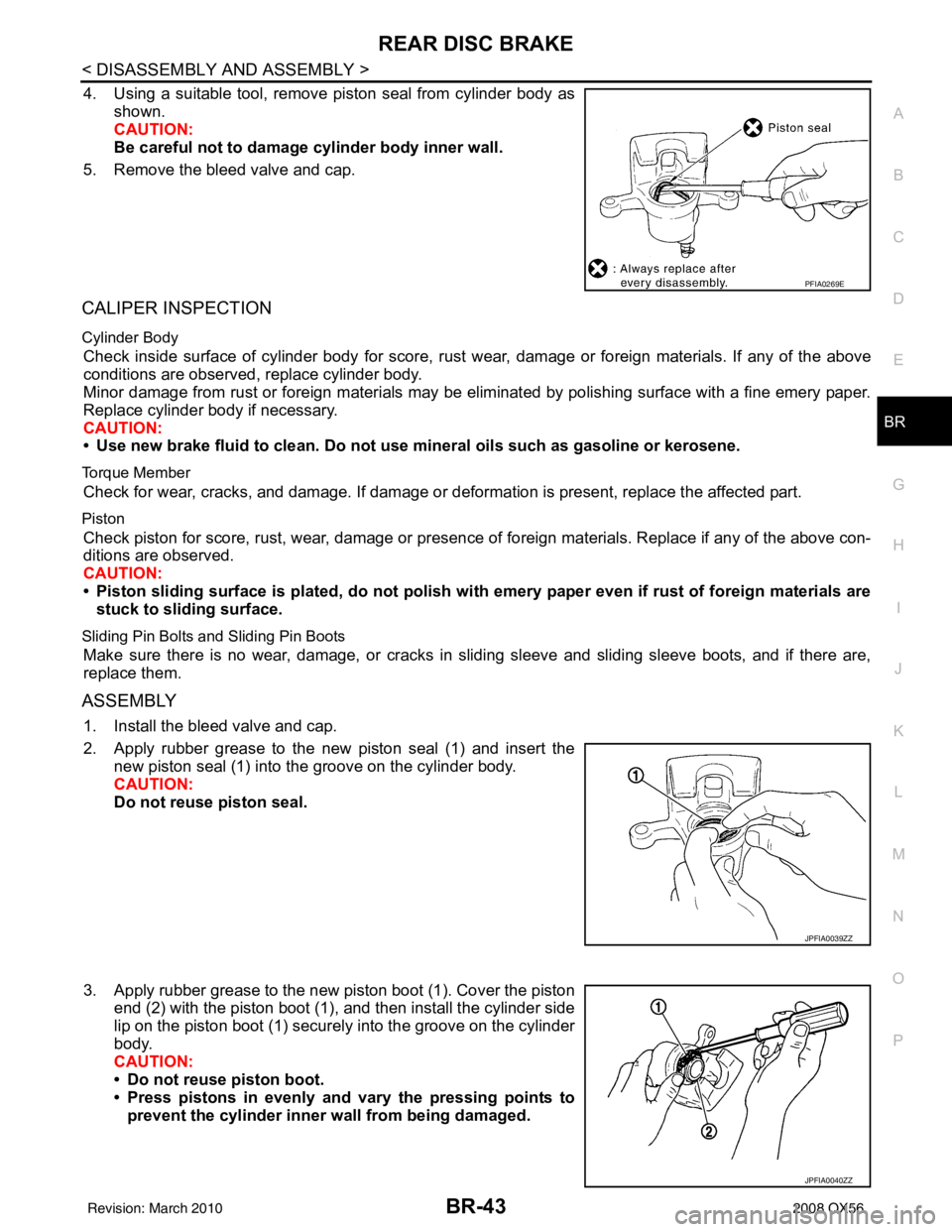
4. Using a suitable tool, remove piston seal from cylinder body as shown.
CAUTION:
Be careful not to damage cylinder body inner wall.
5. Remove the bleed valve and cap.
CALIPER INSPECTION
Cylinder Body
Check inside surface of cylinder body for score, rust wear, damage or foreign materials. If any of the above
conditions are observed, replace cylinder body.
Minor damage from rust or foreign materials may be eliminated by polishing surface with a fine emery paper.
Replace cylinder body if necessary.
CAUTION:
• Use new brake fluid to clean. Do not use mi neral oils such as gasoline or kerosene.
Torque Member
Check for wear, cracks, and damage. If damage or deformation is present, replace the affected part.
Piston
Check piston for score, rust, wear, damage or presence of foreign materials. Replace if any of the above con-
ditions are observed.
CAUTION:
• Piston sliding surface is plated, do not polish with emery paper even if rust of foreign materials are
stuck to sliding surface.
Sliding Pin Bolts and Sliding Pin Boots
Make sure there is no wear, damage, or cracks in sliding sleeve and sliding sleeve boots, and if there are,
replace them.
ASSEMBLY
1. Install the bleed valve and cap.
2. Apply rubber grease to the new piston seal (1) and insert the new piston seal (1) into the groove on the cylinder body.
CAUTION:
Do not reuse piston seal.
3. Apply rubber grease to the new piston boot (1). Cover the piston end (2) with the piston boot (1), and then install the cylinder side
lip on the piston boot (1) securely into the groove on the cylinder
body.
CAUTION:
• Do not reuse piston boot.
• Press pistons in evenly and vary the pressing points toprevent the cylinder inner wall from being damaged.
PFIA0269E
JPFIA0039ZZ
JPFIA0040ZZ
Revision: March 2010 2008 QX56
Page 470 of 4083

BRC-3
C
DE
G H
I
J
K L
M A
B
BRC
N
O P
C1185 ICC UNIT .................................................78
Description .......................................................... ....78
DTC Logic ...............................................................78
Diagnosis Procedure ...............................................78
Special Repair Requirement ...................................79
U1000 CAN COMM CIRCUIT .............................80
Description .......................................................... ....80
DTC Logic ...............................................................80
Diagnosis Procedure ...............................................80
Special Repair Requirement ...................................80
VDC OFF SWITCH ......................................... ....81
Description .......................................................... ....81
Component Function Check ....................................81
Diagnosis Procedure ...............................................81
Component Inspection ............................................82
ABS WARNING LAMP ................................... ....83
Description .......................................................... ....83
Component Function Check ....................................83
Diagnosis Procedure ...............................................83
BRAKE WARNING LAMP ............................. ....84
Description .......................................................... ....84
Component Function Check ....................................84
Diagnosis Procedure ...............................................84
VDC OFF INDICATOR LAMP ............................85
Description .......................................................... ....85
Component Function Check ....................................85
Diagnosis Procedure ...............................................85
SLIP INDICATOR LAMP ....................................86
Description .......................................................... ....86
Component Function Check ....................................86
Diagnosis Procedure ...............................................86
ECU DIAGNOSIS .........................................87
ABS ACTUATOR AND ELECTRIC UNIT
(CONTROL UNIT) .......................................... ....
87
Reference Value ................................................. ....87
Wiring Diagram .......................................................92
Fail-Safe ..................................................................99
DTC No. Index ......................................................100
SYMPTOM DIAGNOSIS ............................102
VDC/TCS/ABS ................................................ ..102
Symptom Table ................................................... ..102
EXCESSIVE ABS FUNCTION OPERATION
FREQUENCY ...................................................
103
Diagnosis Procedure ........................................... ..103
UNEXPECTED PEDAL REACTION ...............104
Diagnosis Procedure ........................................... ..104
THE BRAKING DISTANCE IS LONG .............105
Diagnosis Procedure .............................................105
ABS FUNCTION DOES NOT OPERATE .......106
Diagnosis Procedure .............................................106
PEDAL VIBRATION OR ABS OPERATION
SOUND OCCURS ...........................................
107
Diagnosis Procedure ........................................... ..107
VEHICLE JERKS DURING VDC/TCS/ABS
CONTROL .......................................................
108
Diagnosis Procedure .............................................108
NORMAL OPERATING CONDITION .............109
Description .............................................................109
PRECAUTION ............................................110
PRECAUTIONS ...............................................110
Precaution for Supplemental Restraint System
(SRS) "AIR BAG" and "SEAT BELT PRE-TEN-
SIONER" ............................................................. ..
110
Precaution Necessary for Steering Wheel Rota-
tion After Battery Disconnect .................................
110
Precaution for Brake System .................................111
Precaution for Brake Control .................................111
Precaution for CAN System ...................................112
PREPARATION .........................................113
PREPARATION ...............................................113
Special Service Tool ............................................ ..113
Commercial Service Tool ......................................113
REMOVAL AND INSTALLATION .............114
WHEEL SENSORS .........................................114
Removal and Installation ..................................... ..114
SENSOR ROTOR ............................................115
Removal and Installation .......................................115
ACTUATOR AND ELECTRIC UNIT (ASSEM-
BLY) ................................................................
116
Removal and Installation .......................................116
STEERING ANGLE SENSOR .........................118
Removal and Installation .......................................118
G SENSOR ......................................................119
Removal and Installation .......................................119
Revision: March 2010 2008 QX56
Page 491 of 4083
![INFINITI QX56 2008 Factory Service Manual BRC-24
< FUNCTION DIAGNOSIS >[VDC/TCS/ABS]
DIAGNOSIS SYSTEM [
ABS ACTUATOR AND ELECTRIC UNIT (CONTROL
UNIT)]
DIAGNOSIS SYSTEM [ABS ACTUATOR AND ELECTRIC UNIT (CONTROL
UNIT)]
CONSULT-III Function (AB INFINITI QX56 2008 Factory Service Manual BRC-24
< FUNCTION DIAGNOSIS >[VDC/TCS/ABS]
DIAGNOSIS SYSTEM [
ABS ACTUATOR AND ELECTRIC UNIT (CONTROL
UNIT)]
DIAGNOSIS SYSTEM [ABS ACTUATOR AND ELECTRIC UNIT (CONTROL
UNIT)]
CONSULT-III Function (AB](/img/42/57030/w960_57030-490.png)
BRC-24
< FUNCTION DIAGNOSIS >[VDC/TCS/ABS]
DIAGNOSIS SYSTEM [
ABS ACTUATOR AND ELECTRIC UNIT (CONTROL
UNIT)]
DIAGNOSIS SYSTEM [ABS ACTUATOR AND ELECTRIC UNIT (CONTROL
UNIT)]
CONSULT-III Function (ABS)INFOID:0000000001686255
FUNCTION
CONSULT-III can display each diagnostic item us ing the diagnostic test modes shown following.
SELF-DIAG RESULTS MODE
Operation Procedure
1. Before performing the self-diagnosis, start engine and drive vehicle at 30 km/h (19 MPH) or more for
approximately 1 minute.
How to Erase Self-d iagnosis Results
1. After erasing DTC memory, start engine and drive vehicle at 30 km/h (19 MPH) or more for approximately
1 minute as the final inspection, and make sure that the ABS warning lamp, VDC OFF indicator lamp,
SLIP indicator lamp and brake warning lamp turn OFF.
CAUTION:
If memory cannot be erased, pe rform applicable diagnosis.
NOTE:
• When the wheel sensor malfunctions, after inspecting the wheel sensor system, the ABS warning lamp,
VDC OFF indicator lamp, SLIP indicator lamp and brake warning lamp will not turn OFF even when the
system is normal unless the vehicle is driving at approximately 30 km/h (19 MPH) or more for approxi-
mately 1 minute.
• Brake warning lamp will turn ON in case of parking brake operation (when switch is ON) or of brake fluid level switch operation (when brake fluid is insufficient).
• VDC OFF switch should not stay “ON” position.
Display Item List
Refer to BRC-100, "DTC No. Index".
DATA MONITOR MODE
Display Item List
Diagnostic test mode Function
Work support This mode enables a technician to adjust some devices faster and more accurately by following
the indications on CONSULT-III.
Self-diagnostic results Self-diagnostic results can be read and erased quickly.
Data monitor Input/Output data in the ABS actuator and electric unit (control unit) can be read.
Active test Diagnostic test mode is which CONSULT-III drives some actuators apart from the ABS actuator
and electric unit (control unit) and also shifts some parameters in a specified range.
ECU part number ABS actuator and electric unit (control unit) part number can be read.
CAN diagnostic support monitor The results of transmit/receive diagnosis of CAN communication can be read.
Item
(Unit) Data monitor item selection
Remarks
ECU INPUT
SIGNALS MAIN
SIGNALS SELECTION
FROM MENU
GEAR ××× Gear position judged by transmis-
sion range switch signal is dis-
played.
FR RH SENSOR
(km/h, MPH) ××× Wheel speed calculated by front RH
wheel sensor signal is displayed.
FR LH SENSOR
(km/h, MPH) ××× Wheel speed calculated by front LH
wheel sensor signal is displayed.
RR RH SENSOR
(km/h, MPH) ×××
Wheel speed calculated by rear RH
wheel sensor signal is displayed.
Revision: March 2010
2008 QX56
Page 492 of 4083
![INFINITI QX56 2008 Factory Service Manual DIAGNOSIS SYSTEM [ABS ACTUATOR AND ELECTRIC UNIT (CONTROL
UNIT)]
BRC-25
< FUNCTION DIAGNOSIS > [VDC/TCS/ABS]
C
D
E
G H
I
J
K L
M A
B
BRC
N
O P
RR LH SENSOR
(km/h, MPH) ××× Wheel speed calculated INFINITI QX56 2008 Factory Service Manual DIAGNOSIS SYSTEM [ABS ACTUATOR AND ELECTRIC UNIT (CONTROL
UNIT)]
BRC-25
< FUNCTION DIAGNOSIS > [VDC/TCS/ABS]
C
D
E
G H
I
J
K L
M A
B
BRC
N
O P
RR LH SENSOR
(km/h, MPH) ××× Wheel speed calculated](/img/42/57030/w960_57030-491.png)
DIAGNOSIS SYSTEM [ABS ACTUATOR AND ELECTRIC UNIT (CONTROL
UNIT)]
BRC-25
< FUNCTION DIAGNOSIS > [VDC/TCS/ABS]
C
D
E
G H
I
J
K L
M A
B
BRC
N
O P
RR LH SENSOR
(km/h, MPH) ××× Wheel speed calculated by rear LH
wheel sensor signal is displayed.
BATTERY VOLT
(V) ××× Voltage supplied to ABS actuator
and electric unit (control unit) is dis-
played.
N POSI SIG –– ×Shift position judged by transmis-
sion range switch signal.
P POSI SIG –– ×Shift position judged by transmis-
sion range switch signal.
ACCEL POS SIG
(%) ×
– ×Throttle valve open/close status
judged by CAN communication sig-
nal is displayed.
ENGINE SPEED
(rpm) ×××
Engine speed judged by CAN com-
munication signal is displayed.
STR ANGLE SIG
(deg) ×
– ×Steering angle detected by steering
angle sensor is displayed.
YAW RATE SEN
(d/s) ××× Yaw rate detected by yaw rate sen-
sor is displayed.
SIDE G-SENSOR
(m/s
2) ×
– ×Transverse acceleration detected
by side G-sensor is displayed.
STOP LAMP SW
(ON/OFF) ××× Stop lamp switch (ON/OFF) status
is displayed.
OFF SW
(ON/OFF) ×××
VDC OFF switch (ON/OFF) status
is displayed.
ABS WARN LAMP
(ON/OFF) –
×× ABS warning lamp (ON/OFF) status
is displayed.
SLIP LAMP
(ON/OFF) –
×× SLIP indicator lamp (ON/OFF) sta-
tus is displayed.
FR LH IN SOL
(ON/OFF) –
×× Front LH IN ABS solenoid (ON/
OFF) status is displayed.
FR LH OUT SOL
(ON/OFF) –
×× Front LH OUT ABS solenoid (ON/
OFF) status is displayed.
RR RH IN SOL
(ON/OFF) –
×× Rear RH IN ABS solenoid (ON/
OFF) status is displayed.
RR RH OUT SOL
(ON/OFF) –
×× Rear RH OUT ABS solenoid (ON/
OFF) status is displayed.
FR RH IN SOL
(ON/OFF) –
×× Front RH IN ABS solenoid (ON/
OFF) status is displayed.
FR RH OUT SOL
(ON/OFF) –
×× Front RH OUT ABS solenoid (ON/
OFF) status is displayed.
RR LH IN SOL
(ON/OFF) –
×× Rear LH IN ABS solenoid (ON/OFF)
status is displayed.
RR LH OUT SOL
(ON/OFF) –
×× Rear LH OUT ABS solenoid (ON/
OFF) status is displayed.
OFF LAMP
(ON/OFF) –
×× OFF Lamp (ON/OFF) status is dis-
played.
MOTOR RELAY
(ON/OFF) –
×× ABS motor relay signal (ON/OFF)
status is displayed.
ACTUATOR RLY
(ON/OFF) –
×× ABS actuator relay signal (ON/OFF)
status is displayed.
Item
(Unit) Data monitor item selection
Remarks
ECU INPUT
SIGNALS MAIN
SIGNALS SELE
CTION
FROM MENU
Revision: March 2010 2008 QX56
Page 493 of 4083
![INFINITI QX56 2008 Factory Service Manual BRC-26
< FUNCTION DIAGNOSIS >[VDC/TCS/ABS]
DIAGNOSIS SYSTEM [
ABS ACTUATOR AND ELECTRIC UNIT (CONTROL
UNIT)]
CV1
(ON/OFF) ––× Front side switch-over solenoid
valve (cut valve) (ON/OFF) status i INFINITI QX56 2008 Factory Service Manual BRC-26
< FUNCTION DIAGNOSIS >[VDC/TCS/ABS]
DIAGNOSIS SYSTEM [
ABS ACTUATOR AND ELECTRIC UNIT (CONTROL
UNIT)]
CV1
(ON/OFF) ––× Front side switch-over solenoid
valve (cut valve) (ON/OFF) status i](/img/42/57030/w960_57030-492.png)
BRC-26
< FUNCTION DIAGNOSIS >[VDC/TCS/ABS]
DIAGNOSIS SYSTEM [
ABS ACTUATOR AND ELECTRIC UNIT (CONTROL
UNIT)]
CV1
(ON/OFF) ––× Front side switch-over solenoid
valve (cut valve) (ON/OFF) status is
displayed.
CV2
(ON/OFF) ––× Rear side switch-over solenoid
valve (cut-valve) (O
N/OFF) status is
displayed.
SV1
(ON/OFF) ––× Front side switch-over solenoid
valve (suction valve) (ON/OFF) sta-
tus is displayed.
SV2
(ON/OFF) ––× Rear side switch-over solenoid
valve (suction valve) (ON/OFF) sta-
tus is displayed.
VDC FAIL SIG
(ON/OFF) ––× VDC fail signal (ON/OFF) status is
displayed.
TCS FAIL SIG
(ON/OFF) ––× TCS fail signal (ON/OFF) status is
displayed.
ABS FAIL SIG
(ON/OFF) ––×
ABS fail signal (ON/OFF) status is
displayed.
EBD FAIL SIG
(ON/OFF) ––× EBD fail signal (ON/OFF) status is
displayed.
FLUID LEV SW
(ON/OFF) ×
– ×Brake fluid level switch (ON/OFF)
status is displayed.
EBD SIGNAL
(ON/OFF) ––×
EBD operation (ON/OFF) status is
displayed.
ABS SIGNAL
(ON/OFF) ––× ABS operation (ON/OFF) status is
displayed.
TCS SIGNAL
(ON/OFF) ––× TCS operation (ON/OFF) status is
displayed.
VDC SIGNAL
(ON/OFF) ––×
VDC operation (ON/OFF) status is
displayed.
EBD WARN LAMP –– ×Brake warning lamp (ON/OFF) sta-
tus is displayed.
SLCT LVR POSI ××× Shift position judged by transmis-
sion range switch signal.
R POSI SIG ––×Shift position judged by transmis-
sion range switch signal.
2WD/4WD ––×It recognizes on software whether it
is 2WD and whether it is in 4WD
state.
BST OPER SIG ––×Active booster operation (ON/OFF)
st
atus is
di
splayed.
PRESS SENSOR ×– ×Brake pressure detected by pres-
sure sensor is displayed.
CRANKING SIG ––×The input state of the key SW
START position signal is displayed.
PRESS SEN 2 ––×Brake pressure detected by pres-
sure sensor is displayed.
DELTA S SEN ––×The amount of stroke sensor move-
ments in the active booster detected
by DELTA S SEN is displayed.
Item
(Unit) Data monitor item selection
Remarks
ECU INPUT
SIGNALS MAIN
SIGNALS SELECTION
FROM MENU
Revision: March 2010 2008 QX56
Page 494 of 4083
![INFINITI QX56 2008 Factory Service Manual DIAGNOSIS SYSTEM [ABS ACTUATOR AND ELECTRIC UNIT (CONTROL
UNIT)]
BRC-27
< FUNCTION DIAGNOSIS > [VDC/TCS/ABS]
C
D
E
G H
I
J
K L
M A
B
BRC
N
O P
× : Applicable
–: Not applicable
ACTIVE TEST MODE
CAU INFINITI QX56 2008 Factory Service Manual DIAGNOSIS SYSTEM [ABS ACTUATOR AND ELECTRIC UNIT (CONTROL
UNIT)]
BRC-27
< FUNCTION DIAGNOSIS > [VDC/TCS/ABS]
C
D
E
G H
I
J
K L
M A
B
BRC
N
O P
× : Applicable
–: Not applicable
ACTIVE TEST MODE
CAU](/img/42/57030/w960_57030-493.png)
DIAGNOSIS SYSTEM [ABS ACTUATOR AND ELECTRIC UNIT (CONTROL
UNIT)]
BRC-27
< FUNCTION DIAGNOSIS > [VDC/TCS/ABS]
C
D
E
G H
I
J
K L
M A
B
BRC
N
O P
× : Applicable
–: Not applicable
ACTIVE TEST MODE
CAUTION:
• Do not perform active test while driving vehicle.
• Make sure to completely bleed air from brake system.
• The active test cannot be performed with the ABS warning lamp, VDC OFF indicator lamp, SLIP indi-
cator lamp or brake warning lamp on.
• ABS warning lamp, VDC OFF indicator lamp, SLIP indicator lamp and brake warning lamp are on
during active test.
NOTE:
• When active test is performed while depressing the pedal, the pedal depression amount will change. This is
normal. (Only solenoid valve and ABS motor.)
• “TEST IS STOPPED” is displayed 10 seconds after operation start.
• After “TEST IS STOPPED” is displayed, to perform test again, touch BACK.
Test Item
SOLENOID VALVE• When performing an active test of the ABS function, select the “MAIN SIGNALS” for each test item. In addi-
tion, when performing an active test of the VDC/TCS f unction, select the item menu for each test item.
• For ABS solenoid valve, touch “UP”, “KEEP”, and “D OWN” on the display screen. For ABS solenoid valve
(ACT), touch “UP”, “ACT UP”, “ACT KEEP” and confirm that solenoid valv es operate as shown in the table
below.
RELEASE SW NO –– ×Release switch signal (ON/OFF)
status is displayed. “ON” indicates
that the brake pedal is depressed.
“OFF”“ is that the brake pedal is re-
leased.
RELEASE SW NC –– ×Release switch signal (ON/OFF)
status is displayed. “OFF” indicates
that the brake pedal is depressed
on. “ON” is that the brake pedal is
released.
OHB FAIL –– ×OHB fail status is displayed.
HBA FAIL –– ×HBA fail status is displayed.
OHB SIG –– ×OHB operation (ON/OFF) status is
displayed.
HBA SIG –– ×HBA operation (ON/OFF) status is
displayed.
PRES CTRL ACC –– ×This item is not used for this model.
PRES FAIL ACC –– ×This item is not used for this model.
STP OFF RLY –– ×Stop lamp relay signal (ON/OFF)
status is displayed.
Item
(Unit) Data monitor item selection
Remarks
ECU INPUT
SIGNALS MAIN
SIGNALS SELECTION
FROM MENU
Operation ABS solenoid valve
ABS solenoid valve (ACT)
UP KEEP DOWN UP ACTUA-
TOR UP ACTUA-
TOR KEEP
FR RH SOL
FR RH ABS SOLE-
NOID (ACT) FR RH IN SOL
OFF ON ON OFF OFF OFF
FR RH OUT SOL OFF OFF ON* OFF OFF OFF
FR LH SOL
FR LH ABS SOLE-
NOID (ACT) FR LH IN SOL
OFF ON ON OFF OFF OFF
FR LH OUT SOL OFF OFF ON* OFF OFF OFF
Revision: March 2010 2008 QX56